Operating Instructions
Page 1
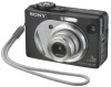
... and retain it for future reference. Refer to these numbers whenever you call upon your computer_________ Troubleshooting Additional information Index DSC-W1/W12 Serial No. DSC-W1/W12 © 2004 Sony Corporation 3-091-535-11(1) Getting started Shooting still images Viewing still images Deleting still images Before advanced operations Advanced still... image printing PictBridge printer) Enjoying movies Enjoying images on the bottom. Record the serial number in the space provided below. Digital Still Camera Operating Instructions Before operating the unit, please read this product.
... and retain it for future reference. Refer to these numbers whenever you call upon your computer_________ Troubleshooting Additional information Index DSC-W1/W12 Serial No. DSC-W1/W12 © 2004 Sony Corporation 3-091-535-11(1) Getting started Shooting still images Viewing still images Deleting still images Before advanced operations Advanced still... image printing PictBridge printer) Enjoying movies Enjoying images on the bottom. Record the serial number in the space provided below. Digital Still Camera Operating Instructions Before operating the unit, please read this product.

Service Manual
Page 1
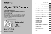
...-described information is available. • Note in The following pages are not shown. DSC-W1/W12 SERVICE MANUAL Ver 1.2 2004.08 Revision History How to use Acrobat Reader 2 LEVEL DSC-W1 US Model Canadian Model Hong Kong Model Australian Model Argentine Model Brazilian Model Tourist Model ...to 5-13 parts list of processing the flexible boards/harnesses are shown. Pages 4-54 and 4-55 and SP-045 flexible boards. DIGITAL STILL CAMERA service manual Level 3. search on printed wiring boards is shown in Lens Frame Installation • Exchange Method of Barrier Assy •...
...-described information is available. • Note in The following pages are not shown. DSC-W1/W12 SERVICE MANUAL Ver 1.2 2004.08 Revision History How to use Acrobat Reader 2 LEVEL DSC-W1 US Model Canadian Model Hong Kong Model Australian Model Argentine Model Brazilian Model Tourist Model ...to 5-13 parts list of processing the flexible boards/harnesses are shown. Pages 4-54 and 4-55 and SP-045 flexible boards. DIGITAL STILL CAMERA service manual Level 3. search on printed wiring boards is shown in Lens Frame Installation • Exchange Method of Barrier Assy •...
Service Manual
Page 2
... strap (1) • "Memory Stick" (32 MB) (1) • CD-ROM (USB driver SPVD-012) (1) • Operating instructions (1) • Soft carrying case (DSC-W12 only) (1) See page 5-15. DSC-W1/W12 x Camera [System] Image device 9.04 mm (1/1.8 type) color CCD Primary color filter Total pixels number of... camera Approx. 5 255 000 pixels Effective pixels number of camera Approx. 5 090 000 pixels Lens Carl Zeiss Vario-Tessar 3 zo om lens f = 7.9 - 23.7 mm ...
... strap (1) • "Memory Stick" (32 MB) (1) • CD-ROM (USB driver SPVD-012) (1) • Operating instructions (1) • Soft carrying case (DSC-W12 only) (1) See page 5-15. DSC-W1/W12 x Camera [System] Image device 9.04 mm (1/1.8 type) color CCD Primary color filter Total pixels number of... camera Approx. 5 255 000 pixels Effective pixels number of camera Approx. 5 090 000 pixels Lens Carl Zeiss Vario-Tessar 3 zo om lens f = 7.9 - 23.7 mm ...

Service Manual
Page 6
DSC-W1/W12 1-3. NOTE IN LENS FRAME INSTALLATION When tightening a screw, have both sides of lens drive circuit. C:13:ss Format the "Memory stick". Insert a new "Memory ... DISPLAY Self-diagnosis display • C: ss: ss You can reverse the camera malfunction yourself. (However, contact your Sony dealer or local authorized Sony service facility when you cannot recover from the camera malfunction.) • E: ss: ss Contact your Sony dealer or local authorized Sony service facility. When failed in the focus and zoom initialization. Turn the...
DSC-W1/W12 1-3. NOTE IN LENS FRAME INSTALLATION When tightening a screw, have both sides of lens drive circuit. C:13:ss Format the "Memory stick". Insert a new "Memory ... DISPLAY Self-diagnosis display • C: ss: ss You can reverse the camera malfunction yourself. (However, contact your Sony dealer or local authorized Sony service facility when you cannot recover from the camera malfunction.) • E: ss: ss Contact your Sony dealer or local authorized Sony service facility. When failed in the focus and zoom initialization. Turn the...

Service Manual
Page 12
... LCD DRIVE, MS CONNECTOR MS-205 flexible CONNECTOR SP-045 flexible SPEAKER ST-100 FLASH DRIVE ST-101 flexible CHARGING CAPACITOR, FLASH UNIT SY-102 CAMERA MODULE, CAMERA DSP, LENS DRIVE, (Including CH-146) SH DSP, FRONT CONTROL, DC/DC CONVERTER SW-422 AUDIO, CONTROL SWITCH US-011 flexible USB CONNECTOR 2-8E...
... LCD DRIVE, MS CONNECTOR MS-205 flexible CONNECTOR SP-045 flexible SPEAKER ST-100 FLASH DRIVE ST-101 flexible CHARGING CAPACITOR, FLASH UNIT SY-102 CAMERA MODULE, CAMERA DSP, LENS DRIVE, (Including CH-146) SH DSP, FRONT CONTROL, DC/DC CONVERTER SW-422 AUDIO, CONTROL SWITCH US-011 flexible USB CONNECTOR 2-8E...

Service Manual
Page 15
DSC-W1/W12 SECTION 3 3. D15 MC A1 - OVERALL BLOCK DIAGRAM (1/2) ( ) : Number in parenthesis ( ) indicates the division number of schematic diagram where the ...10 17 11 20 20 7 19 11 21 19 132 124 3 123 126-129 84 Q105 36 135 27 VSUB CONT 20 Q701 CP101 CAMERA MODULE (1/6) 22 ı 35 45 46 48 CA AD00 - A25 MC CKIO CAM F XFE CS XTG CS LENS TEMP VER EXT CLK...RST Y11 AB11 Y10 AA11 AB10 Y9 F1 AB9 AA10 AA9 D1 Y8 AB8 AA8 E1 AB7 AA7 Y7 C6 AB6 D7 AC8 IC301 CAMERA DSP, SDRAM (KWF BOARD) (2/6) G1 AC22 AC12 AC15 N3 K3 M4 K4 J3 T4 P4 U2 T3 D8 T2 AA12 U3 ...
DSC-W1/W12 SECTION 3 3. D15 MC A1 - OVERALL BLOCK DIAGRAM (1/2) ( ) : Number in parenthesis ( ) indicates the division number of schematic diagram where the ...10 17 11 20 20 7 19 11 21 19 132 124 3 123 126-129 84 Q105 36 135 27 VSUB CONT 20 Q701 CP101 CAMERA MODULE (1/6) 22 ı 35 45 46 48 CA AD00 - A25 MC CKIO CAM F XFE CS XTG CS LENS TEMP VER EXT CLK...RST Y11 AB11 Y10 AA11 AB10 Y9 F1 AB9 AA10 AA9 D1 Y8 AB8 AA8 E1 AB7 AA7 Y7 C6 AB6 D7 AC8 IC301 CAMERA DSP, SDRAM (KWF BOARD) (2/6) G1 AC22 AC12 AC15 N3 K3 M4 K4 J3 T4 P4 U2 T3 D8 T2 AA12 U3 ...

Service Manual
Page 18
... D901 BACKLIGHT A 2.8V D 2.8V Q106, 107 CAM 3.3V CAM 15.5V CAM -7.5V/-8.0V M 5V D 2.8V CP101 CAMERA MODULE (1/6) L102 L103 L104 FB105 FB102 FB103 CH-146 BOARD 54 55 71 53 IC101 52 CCD SIGNAL 57 PROCESSOR, TIMING 56 GENERATOR... CLOCK GENERATOR (2/6) A 3.1V CAM DD ON STRB CHRG A 2.8V D2.8V IC502 1.8V 4 REG 1 (4/6) D 1.2V L301 FB303 FB307 IC301 CAMERA DSP, SDRAM (KWF BOARD) (2/6) PI006 V4 PI007 V3 L502 AC20 PU[6] AD19 PU[0] IC501 MC CAM, SH DSP, FLASH (4/6) SDA(O/D) AD18 XLENZ RST...BOX2 PI 14 SENS Vcc 9 Z BOX1 PI SENS Vcc FOCUS SENSOR ZOOM FG 3-8E MEMORY STICK DSC-W1/W12 3.
... D901 BACKLIGHT A 2.8V D 2.8V Q106, 107 CAM 3.3V CAM 15.5V CAM -7.5V/-8.0V M 5V D 2.8V CP101 CAMERA MODULE (1/6) L102 L103 L104 FB105 FB102 FB103 CH-146 BOARD 54 55 71 53 IC101 52 CCD SIGNAL 57 PROCESSOR, TIMING 56 GENERATOR... CLOCK GENERATOR (2/6) A 3.1V CAM DD ON STRB CHRG A 2.8V D2.8V IC502 1.8V 4 REG 1 (4/6) D 1.2V L301 FB303 FB307 IC301 CAMERA DSP, SDRAM (KWF BOARD) (2/6) PI006 V4 PI007 V3 L502 AC20 PU[6] AD19 PU[0] IC501 MC CAM, SH DSP, FLASH (4/6) SDA(O/D) AD18 XLENZ RST...BOX2 PI 14 SENS Vcc 9 Z BOX1 PI SENS Vcc FOCUS SENSOR ZOOM FG 3-8E MEMORY STICK DSC-W1/W12 3.

Service Manual
Page 21
... dimensions (mm) • Constants of resistors, capacitors, ICs and etc with mark 0 are measured between the measurement points and ground when camera shoots color bar chart of the lens L = About 27 cm (PTB-450) L = About 11 cm (PTB-1450) 2. They are...differ according to the mount table for electrolytics and tantalums. Pattern box • Chip resistors are not used .) Front of pattern box. SCHEMATIC DIAGRAMS DSC-W1/W12 4-2. H Yellow Cyan Green White Magenta Red Blue B B A A=B/2 A Fig. New parts must be obtain. Note : The components identified...
... dimensions (mm) • Constants of resistors, capacitors, ICs and etc with mark 0 are measured between the measurement points and ground when camera shoots color bar chart of the lens L = About 27 cm (PTB-450) L = About 11 cm (PTB-1450) 2. They are...differ according to the mount table for electrolytics and tantalums. Pattern box • Chip resistors are not used .) Front of pattern box. SCHEMATIC DIAGRAMS DSC-W1/W12 4-2. H Yellow Cyan Green White Magenta Red Blue B B A A=B/2 A Fig. New parts must be obtain. Note : The components identified...

Service Manual
Page 22
... 19 20 21 22 23 24 25 26 27 28 29 30 31 32 C108 0.1u 16V CL109 C107 0.1u 16V C110 0.1u 16V FB101 DSC-W1/W12 Precautions for Replacement of the lens. SCHEMATIC DIAGRAMS CD-507 FLEXIBLE BOARD For Schematic Diagram • Refer to strong light. 4-7 4-8 CD-507 In addition..., but there are mounted by the side of CCD Imager • If the CCD imager has been replaced, carry out all the adjustments for the camera section. • As the CCD imager may be measured, because they are included in CCD block assy. 4-2.
... 19 20 21 22 23 24 25 26 27 28 29 30 31 32 C108 0.1u 16V CL109 C107 0.1u 16V C110 0.1u 16V FB101 DSC-W1/W12 Precautions for Replacement of the lens. SCHEMATIC DIAGRAMS CD-507 FLEXIBLE BOARD For Schematic Diagram • Refer to strong light. 4-7 4-8 CD-507 In addition..., but there are mounted by the side of CCD Imager • If the CCD imager has been replaced, carry out all the adjustments for the camera section. • As the CCD imager may be measured, because they are included in CCD block assy. 4-2.

Service Manual
Page 55
... FLEXIBLE) 9-876-736-51 Sony EMCS Co. 2004D0500-1 ©2004.4 Published by DI Technical Support Section DISASSEMBLY a 3. Contents of Automatic Adjustment Program. BLOCK DIAGRAMS OVERALL POWER 4. DSC-W1/W12 Ver 1.0 2004. 04 Revision History SECTION 6 ADJUSTMENTS Link Before starting adjustments Adjusting items when replacing main parts and boards CAMERA SECTION ADJUSTMENTS PREPARATIONS BEFORE ADJUSTMENTS...
... FLEXIBLE) 9-876-736-51 Sony EMCS Co. 2004D0500-1 ©2004.4 Published by DI Technical Support Section DISASSEMBLY a 3. Contents of Automatic Adjustment Program. BLOCK DIAGRAMS OVERALL POWER 4. DSC-W1/W12 Ver 1.0 2004. 04 Revision History SECTION 6 ADJUSTMENTS Link Before starting adjustments Adjusting items when replacing main parts and boards CAMERA SECTION ADJUSTMENTS PREPARATIONS BEFORE ADJUSTMENTS...

Service Manual
Page 56
... 6. ADJUSTMENTS Before Starting Adjustment 6-1 1-1. Preparations 6-4 1-1-3. Connection 6-7 2. Application Environment 6-9 2. Adjustment Items of Data 6-25 1. Camera Adjustment 4 6-20 1-5. Adjusting Method 6-22 1-6. Mode Dial Check 6-28 7. Preparations Before Adjustments 6-3 1-1-1. Function of Each Button ...Setting the Test Mode 6-26 2. Camera System Adjustments 6-12 1-4-1. Adjusting Method 6-14 1. Adjustment Items of Color Shading Adjustment Program 6-9 5. Start of Each Button on page 6-29. - 2 - DSC-W1/W12 Section TABLE OF CONTENTS Title...
... 6. ADJUSTMENTS Before Starting Adjustment 6-1 1-1. Preparations 6-4 1-1-3. Connection 6-7 2. Application Environment 6-9 2. Adjustment Items of Data 6-25 1. Camera Adjustment 4 6-20 1-5. Adjusting Method 6-22 1-6. Mode Dial Check 6-28 7. Preparations Before Adjustments 6-3 1-1-1. Function of Each Button ...Setting the Test Mode 6-26 2. Camera System Adjustments 6-12 1-4-1. Adjusting Method 6-14 1. Adjustment Items of Color Shading Adjustment Program 6-9 5. Start of Each Button on page 6-29. - 2 - DSC-W1/W12 Section TABLE OF CONTENTS Title...

Service Manual
Page 58
..." of data z z VIDEO adjustment Video output level adj. Block replacement Replaced parts Mounted parts replacement Board replacement Flash memory replacement (Camera system control) (With built-in the following table. z zz zz z z F No. CCD white defect compensation check CCD black... SY-102 board (COMPLETE) Adjusting item Adjustment SY-102 board IC501 (Note 1) Initialization of Camera System Adjustment. compensation Mechanical shutter adj. CAMERA adjustment 4 Auto focus illumination check zz zzz zz z z LCD initial data input VCO adj. DSC-W1/W12 1-1.
..." of data z z VIDEO adjustment Video output level adj. Block replacement Replaced parts Mounted parts replacement Board replacement Flash memory replacement (Camera system control) (With built-in the following table. z zz zz z z F No. CCD white defect compensation check CCD black... SY-102 board (COMPLETE) Adjusting item Adjustment SY-102 board IC501 (Note 1) Initialization of Camera System Adjustment. compensation Mechanical shutter adj. CAMERA adjustment 4 Auto focus illumination check zz zzz zz z z LCD initial data input VCO adj. DSC-W1/W12 1-1.

Service Manual
Page 59
... cable 1-827-038-11 Clear chart For PTB-450: J-6080-621-A For PTB-1450: J-6082-560-A Filter for adjustment (SEUS) and HASP key. DSC-W1/W12 6-1. PREPARATIONS BEFORE ADJUSTMENTS 1-1-1. Fig. 6-1-1 6-3 CAMERA SECTION ADJUSTMENTS 1-1. List of Service Tools • Oscilloscope • Color monitor • Vectorscope • Calculating machine capable of each area how to...
... cable 1-827-038-11 Clear chart For PTB-450: J-6080-621-A For PTB-1450: J-6082-560-A Filter for adjustment (SEUS) and HASP key. DSC-W1/W12 6-1. PREPARATIONS BEFORE ADJUSTMENTS 1-1-1. Fig. 6-1-1 6-3 CAMERA SECTION ADJUSTMENTS 1-1. List of Service Tools • Oscilloscope • Color monitor • Vectorscope • Calculating machine capable of each area how to...

Service Manual
Page 61
... operations during this time) Electronic beam scanning frame CRT picture frame Fig. Mode Dial P (Program auto) 2. Digital Zoom (SET UP setting) ......... Contrast (Menu items Normal 13. b (monitor TV picture) Adjust the camera position and direction to obtain the output waveform shown in Fig a and the monitor TV display shown in... using the color bar chart, adjust the picture frame as follows and perform adjustments. 1. EV (Menu items 0EV 6. P.Effect (Menu items Off 11. DSC-W1/W12 Yellow Cyan Green White Magenta Red Blue Yellow Cyan Green White Magenta Red Blue 1-1-3.
... operations during this time) Electronic beam scanning frame CRT picture frame Fig. Mode Dial P (Program auto) 2. Digital Zoom (SET UP setting) ......... Contrast (Menu items Normal 13. b (monitor TV picture) Adjust the camera position and direction to obtain the output waveform shown in Fig a and the monitor TV display shown in... using the color bar chart, adjust the picture frame as follows and perform adjustments. 1. EV (Menu items 0EV 6. P.Effect (Menu items Off 11. DSC-W1/W12 Yellow Cyan Green White Magenta Red Blue Yellow Cyan Green White Magenta Red Blue 1-1-3.

Service Manual
Page 63
... on the PC. 5) Click [Connect] on the SEUS screen to display the SEUS PAGE EDIT screen. 3) Click [File] and load the data from the camera. 4) Click [File] and save all changed . This operation does not write the data to the nonvolatile memory. • Data saving To write the all ...SEUS) is displayed in hexadecimal notation. To prevent the data clear by clicking [Page Edit] on the SEUS screen and enter the page to PC. DSC-W1/W12 1-1-4. To check the data change the page, click [Page] on the SEUS screen before starting the adjustment. Using Method of SEUS Wrong SEUS operation...
... on the PC. 5) Click [Connect] on the SEUS screen to display the SEUS PAGE EDIT screen. 3) Click [File] and load the data from the camera. 4) Click [File] and save all changed . This operation does not write the data to the nonvolatile memory. • Data saving To write the all ...SEUS) is displayed in hexadecimal notation. To prevent the data clear by clicking [Page Edit] on the SEUS screen and enter the page to PC. DSC-W1/W12 1-1-4. To check the data change the page, click [Page] on the SEUS screen before starting the adjustment. Using Method of SEUS Wrong SEUS operation...

Service Manual
Page 64
... with the Automatic Adjustment Program and the Color Shading Adjustment Program. Note: [] (numeric value) of the file name varies depending on the environment of Camera System Adjustment. 1-2-1. DSC-W1/W12 1-2. Accordingly, the Automatic Adjustment Program must be manually operated on Main Menu Screen When the Automatic Adjustment Program started in order to reduce...
... with the Automatic Adjustment Program and the Color Shading Adjustment Program. Note: [] (numeric value) of the file name varies depending on the environment of Camera System Adjustment. 1-2-1. DSC-W1/W12 1-2. Accordingly, the Automatic Adjustment Program must be manually operated on Main Menu Screen When the Automatic Adjustment Program started in order to reduce...

Service Manual
Page 65
DSC-W1/W12 1-2-2. Execute the extracted file (setup.exe), and the installer will start unless the HASP Key is connected. 4. The program will start. 5. Starting Method of successful connection to the camera, the indication at the part A changes to "Connected" and the [Color Shading Adjustment] button and the [Disconnect] button become... be connected to the adjustment mode. Install the program following the instructions given on the task bar, and click the [DSC-W1, P100 Color Shade Adjustment] from the [Programs], and the program will not start . Color Shading Adjustment Program 1.
DSC-W1/W12 1-2-2. Execute the extracted file (setup.exe), and the installer will start unless the HASP Key is connected. 4. The program will start. 5. Starting Method of successful connection to the camera, the indication at the part A changes to "Connected" and the [Color Shading Adjustment] button and the [Disconnect] button become... be connected to the adjustment mode. Install the program following the instructions given on the task bar, and click the [DSC-W1, P100 Color Shade Adjustment] from the [Programs], and the program will not start . Color Shading Adjustment Program 1.

Service Manual
Page 66
DSC-W1/W12 1-3. The Automatic Adjustment Program executes the adjustment items if the VIDEO Adjustment Start button is automatically cancelled and the button color returns to "white".) 6-... occurred in the video adjustment. Button Name Adjustment VIDEO VIDEO Output Adjustment Level Adj. Adjustment Items of VIDEO System Adjustment The adjustment items of the camera. 4 [Release Data Setting] button The data setting at the adjustment is cancelled, the button color returns to "red". Signal Page Address Arbitrary 8F D0 Table...
DSC-W1/W12 1-3. The Automatic Adjustment Program executes the adjustment items if the VIDEO Adjustment Start button is automatically cancelled and the button color returns to "white".) 6-... occurred in the video adjustment. Button Name Adjustment VIDEO VIDEO Output Adjustment Level Adj. Adjustment Items of VIDEO System Adjustment The adjustment items of the camera. 4 [Release Data Setting] button The data setting at the adjustment is cancelled, the button color returns to "red". Signal Page Address Arbitrary 8F D0 Table...

Service Manual
Page 68
CAMERA SYSTEM ADJUSTMENTS 1-4-1. DSC-W1/W12 1-4. During the data setting, the button color changes from "white" to "white".) 6-12 If the adjustment completed successfully, the data setting is cancelled. Function of the camera. 4 [Release Data Setting] button The data setting at the adjustment is automatically cancelled and the button color returns to "red". When the...
CAMERA SYSTEM ADJUSTMENTS 1-4-1. DSC-W1/W12 1-4. During the data setting, the button color changes from "white" to "white".) 6-12 If the adjustment completed successfully, the data setting is cancelled. Function of the camera. 4 [Release Data Setting] button The data setting at the adjustment is automatically cancelled and the button color returns to "red". When the...

Service Manual
Page 69
... Data Input AWB 5800K Check AWB 3200K Check CCD Linearity Check Color Reproduction Adj. Button Name CAMERA Adjustment 1 CAMERA Adjustment 2 (Note 2) CAMERA Adjustment 3 CAMERA Adjustment 4 Adjustment Flange Back Adj. Flange Back Check Color Shading Adj. DSC-W1/W12 1-4-2. Clicking either CAMERA Adjustment Start button allows the adjustment item which item is adjusted. The adjustment conditions of the...
... Data Input AWB 5800K Check AWB 3200K Check CCD Linearity Check Color Reproduction Adj. Button Name CAMERA Adjustment 1 CAMERA Adjustment 2 (Note 2) CAMERA Adjustment 3 CAMERA Adjustment 4 Adjustment Flange Back Adj. Flange Back Check Color Shading Adj. DSC-W1/W12 1-4-2. Clicking either CAMERA Adjustment Start button allows the adjustment item which item is adjusted. The adjustment conditions of the...


