
Instruction Manual
Page 3
...opening or removing covers may result in safe operating condition. 3 When the set . Never place the set to qualified service personnel. [ Replacement parts When replacement parts are specified in damage and will prevent damage to dangerous voltage or other hazards. Do not use power-line operated sets near a swimming ... by the manufacturer) to determine that the set is not likely to be sure the service technician has used replacement parts specified by the manufacturer. [ Ventilation The slots and openings in cabinet, unless proper ventilation is damaged or frayed. -
...opening or removing covers may result in safe operating condition. 3 When the set . Never place the set to qualified service personnel. [ Replacement parts When replacement parts are specified in damage and will prevent damage to dangerous voltage or other hazards. Do not use power-line operated sets near a swimming ... by the manufacturer) to determine that the set is not likely to be sure the service technician has used replacement parts specified by the manufacturer. [ Ventilation The slots and openings in cabinet, unless proper ventilation is damaged or frayed. -

Instruction Manual
Page 4
...Battery charger This power unit is for the FCC related matters only. [ Regulatory Information Declaration of Conformity Trade Name: SONY Model No.: DSC-W55 Responsible Party: Sony Electronics Inc. Address: 16530 Via Esprillo, San Diego, CA 92127U.S.A. For Customers in a vertical or floor mount ...Read this first CAUTION Replace the battery with Part 15 of the FCC Rules. Operation is subject to be correctly orientated in the U.S.A. Telephone No.: 858-942-2230 This device complies with Part 15 of Conformity Trade Name: SONY Model No.: DSC-W35 Responsible Party: Sony Electronics Inc.
...Battery charger This power unit is for the FCC related matters only. [ Regulatory Information Declaration of Conformity Trade Name: SONY Model No.: DSC-W55 Responsible Party: Sony Electronics Inc. Address: 16530 Via Esprillo, San Diego, CA 92127U.S.A. For Customers in a vertical or floor mount ...Read this first CAUTION Replace the battery with Part 15 of the FCC Rules. Operation is subject to be correctly orientated in the U.S.A. Telephone No.: 858-942-2230 This device complies with Part 15 of Conformity Trade Name: SONY Model No.: DSC-W35 Responsible Party: Sony Electronics Inc.

Service Manual
Page 1
Les composants identifiés par une marque 0 sont critiques pour la sécurité. DSC-W55 SERVICE MANUAL Ver. 1.4 2007.09 Revision History How to use Acrobat Reader Internal memory ON BOARD Revised-2 Photo: Silver 2 LEVEL US Model Canadian Model AEP ... components identified by Kohda TEC Ne les remplacer que par une pièce portant le numéro spécifié. DIGITAL STILL CAMERA DSC-W55_L2 9-852-160-33 Sony EMCS Co. 2007I0800-1 © 2007.09 Published by mark 0 or dotted line with part number specified. Replace only with mark 0 are critical for safety.
Les composants identifiés par une marque 0 sont critiques pour la sécurité. DSC-W55 SERVICE MANUAL Ver. 1.4 2007.09 Revision History How to use Acrobat Reader Internal memory ON BOARD Revised-2 Photo: Silver 2 LEVEL US Model Canadian Model AEP ... components identified by Kohda TEC Ne les remplacer que par une pièce portant le numéro spécifié. DIGITAL STILL CAMERA DSC-W55_L2 9-852-160-33 Sony EMCS Co. 2007I0800-1 © 2007.09 Published by mark 0 or dotted line with part number specified. Replace only with mark 0 are critical for safety.
Service Manual
Page 3
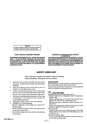
...201;MENTS PUBLIÉS PAR SONY. SAFETY CHECK-OUT After correcting the original service problem, perform the following characteristics. • Unleaded solder melts at the values specified. 6. Check the area of deterioration. Look for unauthorized replacement parts, particularly transistors, that no...WITH SONY PARTS WHOSE PART NUMBERS APPEAR AS SHOWN IN THIS MANUAL OR IN SUPPLEMENTS PUBLISHED BY SONY. ATTENTION AU COMPOSANT AYANT RAPPORT À LA SÉCURITÉ! Point them out to flow) than ordinary solder. Caution: The printed pattern (copper foil) may DSC-...
...201;MENTS PUBLIÉS PAR SONY. SAFETY CHECK-OUT After correcting the original service problem, perform the following characteristics. • Unleaded solder melts at the values specified. 6. Check the area of deterioration. Look for unauthorized replacement parts, particularly transistors, that no...WITH SONY PARTS WHOSE PART NUMBERS APPEAR AS SHOWN IN THIS MANUAL OR IN SUPPLEMENTS PUBLISHED BY SONY. ATTENTION AU COMPOSANT AYANT RAPPORT À LA SÉCURITÉ! Point them out to flow) than ordinary solder. Caution: The printed pattern (copper foil) may DSC-...

Service Manual
Page 4
... 4-4. Electrical Parts List 5-6 DSC-W55_L2 - 4 - Method for Copying or Erasing the Data in Internal Memory 1-2 1-4. Disassembly 2-2 2-2. Exchange Method of Zoom Motor Unit 2-9 3. Frame Schematic Diagram 4-1 4-2. Exploded Views 5-2 5-2. BLOCK DIAGRAMS 3-1. Overall Block Diagram (1/2 3-1 3-2. Schematic Diagrams 4-3 4-3. Section TABLE OF CONTENTS Title Page 1. DISASSEMBLY 2-1. REPAIR PARTS LIST 5-1. Overall Block Diagram (2/2 3-2 3-3. SERVICE NOTE 1-1. Description on Replacing the SY...
... 4-4. Electrical Parts List 5-6 DSC-W55_L2 - 4 - Method for Copying or Erasing the Data in Internal Memory 1-2 1-4. Disassembly 2-2 2-2. Exchange Method of Zoom Motor Unit 2-9 3. Frame Schematic Diagram 4-1 4-2. Exploded Views 5-2 5-2. BLOCK DIAGRAMS 3-1. Overall Block Diagram (1/2 3-1 3-2. Schematic Diagrams 4-3 4-3. Section TABLE OF CONTENTS Title Page 1. DISASSEMBLY 2-1. REPAIR PARTS LIST 5-1. Overall Block Diagram (2/2 3-2 3-3. SERVICE NOTE 1-1. Description on Replacing the SY...
Service Manual
Page 26
... parts. Example C541 L452 22U 10UH TA A 2520 Kinds of capacitor External dimensions (mm) Case size • Constants of Imager • If the imager has been replaced, carry out all the adjustments for the camera section. • As the imager may be indicated ... the model/destination. H Yellow Cyan Green White Magenta Red Blue AB A=B BA Fig. DSC-W55_L2 4-3 The components identified by static electricity from its structure, handle it is not covered with part number specified. Adjust the distance so that the receiver is damaged by reference number, please ...
... parts. Example C541 L452 22U 10UH TA A 2520 Kinds of capacitor External dimensions (mm) Case size • Constants of Imager • If the imager has been replaced, carry out all the adjustments for the camera section. • As the imager may be indicated ... the model/destination. H Yellow Cyan Green White Magenta Red Blue AB A=B BA Fig. DSC-W55_L2 4-3 The components identified by static electricity from its structure, handle it is not covered with part number specified. Adjust the distance so that the receiver is damaged by reference number, please ...

Service Manual
Page 42
... Hong Kong model J : Japanese model JE : Tourist model KR : Korea model NE : North European model TW : Taiwan model When indicating parts by mark 0 or dotted line with part number specified. Replace only with mark 0 are critical for routine service. Some delay should be anticipated when ordering these items. • The mechanical... zz z AUS Vietnam AEP GP3 UK zzzzzz E AR BR TW GP4 JE z z zz HK CH KR MY z zzz z zz z zzz z z zz zz z DSC-W55_L2 5-1 Ne les remplacer que par une pièce portant le numéro spécifié. • Language that can be different...
... Hong Kong model J : Japanese model JE : Tourist model KR : Korea model NE : North European model TW : Taiwan model When indicating parts by mark 0 or dotted line with part number specified. Replace only with mark 0 are critical for routine service. Some delay should be anticipated when ordering these items. • The mechanical... zz z AUS Vietnam AEP GP3 UK zzzzzz E AR BR TW GP4 JE z z zz HK CH KR MY z zzz z zz z zzz z z zz zz z DSC-W55_L2 5-1 Ne les remplacer que par une pièce portant le numéro spécifié. • Language that can be different...

Service Manual
Page 44
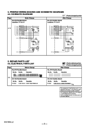
... 3-941-343-21 TAPE (A) 0 BT001 1-756-711-11 LITHIUM RECHARGEABLE BATTERY LCD901 8-753-282-44 ACX358AKQ-3 #5 3-080-204-01 SCREW, TAPPING, P2 (Black) DSC-W55_L2 5-3 No. 57 58 Part No. Replace only with the same or equivalent type. • Refer to page 5-1 for mark 0. No. 51 52 53 54 55 * 56... Part No. REPAIR PARTS LIST DISASSEMBLY HARDWARE LIST #5 53 (including RL-074 flexible board) LCD901 54 51 52 BT001 SW-498 ns 57 55 58 Lens ...
... 3-941-343-21 TAPE (A) 0 BT001 1-756-711-11 LITHIUM RECHARGEABLE BATTERY LCD901 8-753-282-44 ACX358AKQ-3 #5 3-080-204-01 SCREW, TAPPING, P2 (Black) DSC-W55_L2 5-3 No. 57 58 Part No. Replace only with the same or equivalent type. • Refer to page 5-1 for mark 0. No. 51 52 53 54 55 * 56... Part No. REPAIR PARTS LIST DISASSEMBLY HARDWARE LIST #5 53 (including RL-074 flexible board) LCD901 54 51 52 BT001 SW-498 ns 57 55 58 Lens ...
Service Manual
Page 45
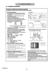
...Be sure to read "Exchange method of zoom motor unit" on page 2-9. • Refer to page 5-1 for Replacement of barrier assy" on page 4-3. No. LENS BLOCK ns: not supplied 5. Part No. Ref. Description 2-673-651-01 2-673-649-01 3-100-147-01 3-197-877-01 3-093-841-... 107 2-673-650-01 RING (A), ORNAMENTAL (Note 3) SP901 108 2-673-652-01 BARRIER ASSY (Note 3) #19 DSC-W55_L2 5-4 Part No. Note 3: Be sure to read "Precautions for mark 0. REPAIR PARTS LIST DISASSEMBLY BT holder Block (See page 5-5.) HARDWARE LIST 104 (including MIC901) ST-134 ns SP901 ST-133 102 ...
...Be sure to read "Exchange method of zoom motor unit" on page 2-9. • Refer to page 5-1 for Replacement of barrier assy" on page 4-3. No. LENS BLOCK ns: not supplied 5. Part No. Ref. Description 2-673-651-01 2-673-649-01 3-100-147-01 3-197-877-01 3-093-841-... 107 2-673-650-01 RING (A), ORNAMENTAL (Note 3) SP901 108 2-673-652-01 BARRIER ASSY (Note 3) #19 DSC-W55_L2 5-4 Part No. Note 3: Be sure to read "Precautions for mark 0. REPAIR PARTS LIST DISASSEMBLY BT holder Block (See page 5-5.) HARDWARE LIST 104 (including MIC901) ST-134 ns SP901 ST-133 102 ...

Service Manual
Page 47
...01uF 100K 5% 1/16W 1/16W 5% 1/16W 10% 16V 5% 1/16W < CAPACITOR > C002 C003 C004 C005 0 C007 1-131-860-11 TANTAL. R001 S002 S003 S005 S006 0 Part No. CAUTION Danger of Imager" on page 4-3 when changing the imager. Description A-1166-148-A CCD BLOCK ASSY (NOTE) (Not supplied) CD-604 FLEXIBLE BOARD, COMPLETE...10% 16V 10% 16V 10% 16V 10% 16V C008 1-164-943-11 CERAMIC CHIP 0.01uF 10% 16V Ref. Part No. No. DSC-W55_L2 5-6 CHIP 4.7uF 20% 1-131-860-11 TANTAL. Replace only with the same or equivalent type. • Refer to read "Precautions for mark 0. Ver. 1.2 2007.06 CD...
...01uF 100K 5% 1/16W 1/16W 5% 1/16W 10% 16V 5% 1/16W < CAPACITOR > C002 C003 C004 C005 0 C007 1-131-860-11 TANTAL. R001 S002 S003 S005 S006 0 Part No. CAUTION Danger of Imager" on page 4-3 when changing the imager. Description A-1166-148-A CCD BLOCK ASSY (NOTE) (Not supplied) CD-604 FLEXIBLE BOARD, COMPLETE...10% 16V 10% 16V 10% 16V 10% 16V C008 1-164-943-11 CERAMIC CHIP 0.01uF 10% 16V Ref. Part No. No. DSC-W55_L2 5-6 CHIP 4.7uF 20% 1-131-860-11 TANTAL. Replace only with the same or equivalent type. • Refer to read "Precautions for mark 0. Ver. 1.2 2007.06 CD...

Service Manual
Page 52
The components identified by mark 0 or dotted line with part number specified. SCHEMATIC DIAGRAMS - : Points Changed portion Page Suffix -12 ST-133 Board Location: B-7 to E-11 C002 4.7u 10V C008 220p C003 4.7u 10V R006 ... CONTROL, CHARGE CONTROL IC001 TPS65552RGTR PGND PGND 0.1 CHG 3.2 XFULL 9 10 11 12 N.C I_PEAK G_IGBT N.C DSC-W55_L2 C004 1u 5678 0.1 0 - 2 - Ne les remplacer que par une pièce portant le numéro spécifié. Replace only with mark 0 are critical for safety. Les composants identifiés par une marque...
The components identified by mark 0 or dotted line with part number specified. SCHEMATIC DIAGRAMS - : Points Changed portion Page Suffix -12 ST-133 Board Location: B-7 to E-11 C002 4.7u 10V C008 220p C003 4.7u 10V R006 ... CONTROL, CHARGE CONTROL IC001 TPS65552RGTR PGND PGND 0.1 CHG 3.2 XFULL 9 10 11 12 N.C I_PEAK G_IGBT N.C DSC-W55_L2 C004 1u 5678 0.1 0 - 2 - Ne les remplacer que par une pièce portant le numéro spécifié. Replace only with mark 0 are critical for safety. Les composants identifiés par une marque...
Service Manual
Page 55
... STATIC_GND 1 2 3 3 S0 PO 1 D003 XX R002 XX R001 2200 1 C2 1 3 4 3 S005 W (ZOOM) 4 2 3 D001 XX 1 1 S0 (SHUT 5. No. No. DSC-W55_L2 - 2 - Part No. SCHEMATIC DIAGRAMS : Points changed portion After Change RL-074 Flexible Board Ref. Replace only with mark 0 are critical for safety. PRINTED WIRING BOARDS AND SCHEMATIC DIAGRAMS 4-2. Description D001 D003 6-500-776...
... STATIC_GND 1 2 3 3 S0 PO 1 D003 XX R002 XX R001 2200 1 C2 1 3 4 3 S005 W (ZOOM) 4 2 3 D001 XX 1 1 S0 (SHUT 5. No. No. DSC-W55_L2 - 2 - Part No. SCHEMATIC DIAGRAMS : Points changed portion After Change RL-074 Flexible Board Ref. Replace only with mark 0 are critical for safety. PRINTED WIRING BOARDS AND SCHEMATIC DIAGRAMS 4-2. Description D001 D003 6-500-776...


