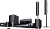

Child Safety: It Makes A Difference Where Your TV Stands
Page 1
... Manager of the International CES® and is large enough to support the weight of your television (and other electronic components). 2 Use appropriate angle braces, straps and anchors to secure your furniture to the wall (but never screw anything directly into the TV). 3 ... a Sector of the Electronic Industries Alliance Many homes, in fact, have a television in your family and friends. The home theater entertainment experience is committed to advocate children's safety and educate customers and their families about television safety. The Consumer Electronics Association formed...
... Manager of the International CES® and is large enough to support the weight of your television (and other electronic components). 2 Use appropriate angle braces, straps and anchors to secure your furniture to the wall (but never screw anything directly into the TV). 3 ... a Sector of the Electronic Industries Alliance Many homes, in fact, have a television in your family and friends. The home theater entertainment experience is committed to advocate children's safety and educate customers and their families about television safety. The Consumer Electronics Association formed...

Limited Warranty (U.S. Only)
Page 1
...period or for the applicable labor charge. 4-557-172-03 General Stereo/Hifi Components/Tape Decks ® CD Players/Mini Disc Players/Audio Systems Hifi Audio LIMITED WARRANTY (U.S. In the event of incidental or consequential damages, or allow limitations on how long an implied warranty lasts, so... the above limitations or exclusions may not apply to the software. If Sony elects to commercial use ; Any parts or product replaced under this Labor Warranty has expired but not limited to product issues due to replace the product...
...period or for the applicable labor charge. 4-557-172-03 General Stereo/Hifi Components/Tape Decks ® CD Players/Mini Disc Players/Audio Systems Hifi Audio LIMITED WARRANTY (U.S. In the event of incidental or consequential damages, or allow limitations on how long an implied warranty lasts, so... the above limitations or exclusions may not apply to the software. If Sony elects to commercial use ; Any parts or product replaced under this Labor Warranty has expired but not limited to product issues due to replace the product...
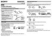
To stabilize S-AIR reception
Page 1
...are separated from the above electronic equipment, or place where S-AIR reception is stable. ©2009 Sony Corporation Printed in the room) of the S-AIR main unit and sub unit is placed When using radio signals - (1) 4-136-147-11(1) English To stabilize S-AIR reception Read the following . ... depth into the slots of the S-AIR main unit and sub unit respectively. Confirm that S-AIR products are inserted correctly. To use a radio frequency of each S-AIR product. Certain electronic equipment or other cords) away from metal doors or tables. Place so that the ...
...are separated from the above electronic equipment, or place where S-AIR reception is stable. ©2009 Sony Corporation Printed in the room) of the S-AIR main unit and sub unit is placed When using radio signals - (1) 4-136-147-11(1) English To stabilize S-AIR reception Read the following . ... depth into the slots of the S-AIR main unit and sub unit respectively. Confirm that S-AIR products are inserted correctly. To use a radio frequency of each S-AIR product. Certain electronic equipment or other cords) away from metal doors or tables. Place so that the ...
Operating Instructions
Page 2
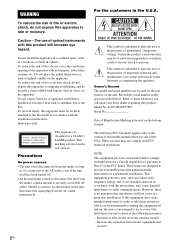
...rear exterior of the unit. Should you call upon your Sony dealer regarding this apparatus to rain or moisture. Owner's Record The model and serial numbers are designed to radio communications. DAV-HDX587WC Serial No Date of Manufacture Marking is connected to the ... the presence of uninsulated "dangerous voltage" within the product's enclosure that interference will increase eye hazard. This symbol is used in accordance with the instructions, may cause harmful interference to provide reasonable protection against harmful interference in accordance with the installation...
...rear exterior of the unit. Should you call upon your Sony dealer regarding this apparatus to rain or moisture. Owner's Record The model and serial numbers are designed to radio communications. DAV-HDX587WC Serial No Date of Manufacture Marking is connected to the ... the presence of uninsulated "dangerous voltage" within the product's enclosure that interference will increase eye hazard. This symbol is used in accordance with the instructions, may cause harmful interference to provide reasonable protection against harmful interference in accordance with the installation...
Operating Instructions
Page 3
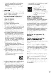
...specified by the manufacturer, or sold with the apparatus. ENERGY STAR® is used, use this apparatus during lightning storms or when unused for your authority to OET65. As an ENERGY STAR® partner, Sony Corporation has determined that to avoid injury from that this device. For the wireless... (EZW-RT10/EZW-RT10A) This Class B digital apparatus complies with RSS-Gen of time. 14) Refer all instructions. 5) Do not use caution when moving the cart/apparatus combination to which the receiver is damaged, liquid has been spilled or objects have fallen into your outlet,...
...specified by the manufacturer, or sold with the apparatus. ENERGY STAR® is used, use this apparatus during lightning storms or when unused for your authority to OET65. As an ENERGY STAR® partner, Sony Corporation has determined that to avoid injury from that this device. For the wireless... (EZW-RT10/EZW-RT10A) This Class B digital apparatus complies with RSS-Gen of time. 14) Refer all instructions. 5) Do not use caution when moving the cart/apparatus combination to which the receiver is damaged, liquid has been spilled or objects have fallen into your outlet,...

Operating Instructions
Page 4
...be authorized by Macrovision, and is intended for home and other limited viewing uses only unless otherwise authorized by U.S. "PLAYSTATION" is prohibited. "S-AIR" and its logo are trademarks of Sony Computer Entertainment Inc. Reverse engineering or disassembly is a trademark of Dolby Laboratories...II) adaptive matrix surround decoder and the DTS** Digital Surround System. * Manufactured under U.S. Dolby, Pro Logic, and the double-D symbol are trademarks of DTS, Inc. © 1996-2008 DTS, Inc. "BRAVIA" is protected by Macrovision. About These Operating Instructions •...
...be authorized by Macrovision, and is intended for home and other limited viewing uses only unless otherwise authorized by U.S. "PLAYSTATION" is prohibited. "S-AIR" and its logo are trademarks of Sony Computer Entertainment Inc. Reverse engineering or disassembly is a trademark of Dolby Laboratories...II) adaptive matrix surround decoder and the DTS** Digital Surround System. * Manufactured under U.S. Dolby, Pro Logic, and the double-D symbol are trademarks of DTS, Inc. © 1996-2008 DTS, Inc. "BRAVIA" is protected by Macrovision. About These Operating Instructions •...

Operating Instructions
Page 5
...sound wirelessly. • S-AIR receiver (supplied): You can enjoy system sound in another room. The following S-AIR products can be purchased as an option (the S-AIR product lineup differs depending on the S-AIR function, see "Using an S-AIR Product" (page 66). 5US About the S-AIR function... The system is used with the S-AIR function, which allows transmission of sound between S-AIR products wirelessly. The surround amplifier...
...sound wirelessly. • S-AIR receiver (supplied): You can enjoy system sound in another room. The following S-AIR products can be purchased as an option (the S-AIR product lineup differs depending on the S-AIR function, see "Using an S-AIR Product" (page 66). 5US About the S-AIR function... The system is used with the S-AIR function, which allows transmission of sound between S-AIR products wirelessly. The surround amplifier...
Operating Instructions
Page 6
... 5 Playable Discs 7 Getting Started Step 1: Installing the System .......12 Step 2: Connecting the System ...21 Step 3: Performing the Quick Setup 29 Step 4: Selecting the Source .......32 Step 5: Enjoying Surround Sound 33 Disc Playing a Disc 36 Using Play Mode 41 Searching/Selecting Disc Contents ....... 44 Playing ...Changing the System Settings by Using the Setup Display 52 Tuner Presetting Radio Stations 60 Listening to the Radio 61 Control for HDMI/External Audio Device Using the Control for HDMI Function for "BRAVIA" Sync 63 Using the DIGITAL MEDIA PORT Adapter 65 Using an S-AIR...
... 5 Playable Discs 7 Getting Started Step 1: Installing the System .......12 Step 2: Connecting the System ...21 Step 3: Performing the Quick Setup 29 Step 4: Selecting the Source .......32 Step 5: Enjoying Surround Sound 33 Disc Playing a Disc 36 Using Play Mode 41 Searching/Selecting Disc Contents ....... 44 Playing ...Changing the System Settings by Using the Setup Display 52 Tuner Presetting Radio Stations 60 Listening to the Radio 61 Control for HDMI/External Audio Device Using the Control for HDMI Function for "BRAVIA" Sync 63 Using the DIGITAL MEDIA PORT Adapter 65 Using an S-AIR...
Operating Instructions
Page 11
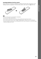
... drop any foreign object into the remote Insert two R6 (size AA) batteries (supplied) by matching the 3 and # ends on the unit. To use the remote for an extended period of time, remove the batteries to direct sunlight or lighting apparatus. Doing so may cause a malfunction. • If ...you do not intend to use the remote, point it at the remote sensor on the batteries to the markings inside the compartment. Getting Started Inserting batteries into the remote casing...
... drop any foreign object into the remote Insert two R6 (size AA) batteries (supplied) by matching the 3 and # ends on the unit. To use the remote for an extended period of time, remove the batteries to direct sunlight or lighting apparatus. Doing so may cause a malfunction. • If ...you do not intend to use the remote, point it at the remote sensor on the batteries to the markings inside the compartment. Getting Started Inserting batteries into the remote casing...

Operating Instructions
Page 12
...be placed anywhere in the room. If you can be between 1.0 to 7.0 meters. Getting Started Step 1: Installing the System Positioning the system For the best possible surround sound, place all speakers at the same distance as it may result. • Do not... Front left speaker (L) Center speaker B Front right speaker (R) A A A A C A C Surround left speaker (L) Surround right speaker (R) Note • Use caution when placing the speakers and/or speaker stands attached to the listening position (C). The subwoofer can move the center speaker up to 1.6 meters closer...
...be placed anywhere in the room. If you can be between 1.0 to 7.0 meters. Getting Started Step 1: Installing the System Positioning the system For the best possible surround sound, place all speakers at the same distance as it may result. • Do not... Front left speaker (L) Center speaker B Front right speaker (R) A A A A C A C Surround left speaker (L) Surround right speaker (R) Note • Use caution when placing the speakers and/or speaker stands attached to the listening position (C). The subwoofer can move the center speaker up to 1.6 meters closer...

Operating Instructions
Page 14
Getting Started Assembling the speakers Before connecting the speakers, attach the speaker stand to the speaker. (For the front speakers) Use the parts as follows: • Front speakers (2) • Speaker cords (2, red/white) • Posts (2) • Bases (2) • Screws (black) (4) • Screws (with washer) (4) For details ... cords to avoid damaging the floor when you assemble the speakers. Note • Spread a cloth on the wall (page 19). 14US Tip • You can use the speaker without the speaker stand by installing it on the floor to the SPEAKER jacks, see page 21.
Getting Started Assembling the speakers Before connecting the speakers, attach the speaker stand to the speaker. (For the front speakers) Use the parts as follows: • Front speakers (2) • Speaker cords (2, red/white) • Posts (2) • Bases (2) • Screws (black) (4) • Screws (with washer) (4) For details ... cords to avoid damaging the floor when you assemble the speakers. Note • Spread a cloth on the wall (page 19). 14US Tip • You can use the speaker without the speaker stand by installing it on the floor to the SPEAKER jacks, see page 21.

Operating Instructions
Page 15
... the speaker depending on the screw positions. Rear of the speaker Example: Lowest position A B C D Post Secure two screws (with washer). You can be increased by using the holes in order from A to the holes on the post faces the front of the speaker. Getting Started 1 Insert the post into the hole...
... the speaker depending on the screw positions. Rear of the speaker Example: Lowest position A B C D Post Secure two screws (with washer). You can be increased by using the holes in order from A to the holes on the post faces the front of the speaker. Getting Started 1 Insert the post into the hole...

Operating Instructions
Page 16
Thread the speaker cord into the end of the speaker 16US The connector and color tube of the speaker cords are the same color as follows: • Front left speaker (L): White • Front right speaker (R): Red Be careful with the orientation of the jacks to be connected. Bottom of the base Top of the base Post Speaker cord , , Base Rear of the post that has two holes. Getting Started 3 Thread the speaker cord through the hole in the base and post. Use the speaker cords as the label of the post.
Thread the speaker cord into the end of the speaker 16US The connector and color tube of the speaker cords are the same color as follows: • Front left speaker (L): White • Front right speaker (R): Red Be careful with the orientation of the jacks to be connected. Bottom of the base Top of the base Post Speaker cord , , Base Rear of the post that has two holes. Getting Started 3 Thread the speaker cord through the hole in the base and post. Use the speaker cords as the label of the post.

Operating Instructions
Page 19
... cords to the appropriate terminals on a wall Caution • Contact a screw shop or installer for information regarding the wall material or screws to be used. • Use screws that are suitable for the wall material and strength. Install the speakers on the back of each speaker. Getting Started Installing the speakers on... (5/32 inch) 30 mm (1 3/16 inches) 5 mm (7/32 inch) 10 mm (13/32 inch) Hole on a vertical and flat wall where reinforcement is applied. • Sony is especially fragile, attach the screws securely to a beam.
... cords to the appropriate terminals on a wall Caution • Contact a screw shop or installer for information regarding the wall material or screws to be used. • Use screws that are suitable for the wall material and strength. Install the speakers on the back of each speaker. Getting Started Installing the speakers on... (5/32 inch) 30 mm (1 3/16 inches) 5 mm (7/32 inch) 10 mm (13/32 inch) Hole on a vertical and flat wall where reinforcement is applied. • Sony is especially fragile, attach the screws securely to a beam.
Operating Instructions
Page 22
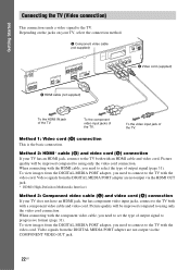
... input jack of output signal to the TV both with a component video cable and video cord. Picture quality will be improved compared to using only the video cord connection. Getting Started Connecting the TV (Video connection) This connection sends a video signal to set the type of the...of output signal (page 31). Method 1: Video cord (A) connection This is the basic connection. Picture quality will be improved compared to using only the video cord connection. To view images from the DIGITAL MEDIA PORT adapter are not output via the COMPONENT VIDEO OUT jack. 22US
... input jack of output signal to the TV both with a component video cable and video cord. Picture quality will be improved compared to using only the video cord connection. Getting Started Connecting the TV (Video connection) This connection sends a video signal to set the type of the...of output signal (page 31). Method 1: Video cord (A) connection This is the basic connection. Picture quality will be improved compared to using only the video cord connection. To view images from the DIGITAL MEDIA PORT adapter are not output via the COMPONENT VIDEO OUT jack. 22US

Operating Instructions
Page 24
Tip • You can also use other components You can enjoy connected components via the system's speakers. When disconnecting, pull out while pressing . You can connect another component, such as a VCR, digital satellite receiver, or PlayStation, to the TV/VIDEO (AUDIO ...
Tip • You can also use other components You can enjoy connected components via the system's speakers. When disconnecting, pull out while pressing . You can connect another component, such as a VCR, digital satellite receiver, or PlayStation, to the TV/VIDEO (AUDIO ...

Operating Instructions
Page 26
... 75 26US Tip • Adjust the direction of the AM loop antenna (aerial) for best AM broadcast sound. • If you have poor FM reception, use a 75-ohm coaxial cable (not supplied) to connect the unit to fully extend the FM wire antenna (aerial). • After connecting the FM wire antenna... 75 or AM loop antenna (aerial) (supplied) FM wire antenna (aerial) (supplied) Note • Keep the AM loop antenna (aerial) and cord away from the system or other AV components, as noise may result. • Be sure to an outdoor FM antenna (aerial) as possible.
... 75 26US Tip • Adjust the direction of the AM loop antenna (aerial) for best AM broadcast sound. • If you have poor FM reception, use a 75-ohm coaxial cable (not supplied) to connect the unit to fully extend the FM wire antenna (aerial). • After connecting the FM wire antenna... 75 or AM loop antenna (aerial) (supplied) FM wire antenna (aerial) (supplied) Note • Keep the AM loop antenna (aerial) and cord away from the system or other AV components, as noise may result. • Be sure to an outdoor FM antenna (aerial) as possible.

Operating Instructions
Page 27
For details of S-AIR products, see "Using an S-AIR Product" (page 66). To transmit sound from the unit to the operating instructions of the S-AIR receiver. For details, refer to an S-AIR ...
For details of S-AIR products, see "Using an S-AIR Product" (page 66). To transmit sound from the unit to the operating instructions of the S-AIR receiver. For details, refer to an S-AIR ...

Operating Instructions
Page 29
...4:3 PAN SCAN BLACK LEVEL (COMPONENT OUT): OFF PAUSE MODE: AUTO C/X/x/c, DISPLAY 1 Turn on the area. The Setup Display for using the system. Note • Make sure that the signal from the system appears on the TV screen. [Press [ENTER] to run QUICK SETUP.] appears at the bottom of the TV to be... connected appears. Getting Started Step 3: Performing the Quick Setup Follow the Steps below to make the basic adjustments for selecting the language used in the on...
...4:3 PAN SCAN BLACK LEVEL (COMPONENT OUT): OFF PAUSE MODE: AUTO C/X/x/c, DISPLAY 1 Turn on the area. The Setup Display for using the system. Note • Make sure that the signal from the system appears on the TV screen. [Press [ENTER] to run QUICK SETUP.] appears at the bottom of the TV to be... connected appears. Getting Started Step 3: Performing the Quick Setup Follow the Steps below to make the basic adjustments for selecting the language used in the on...
Operating Instructions
Page 30
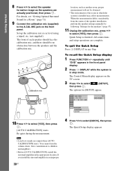
...actually positioned, then press . To quit the Quick Setup Press DISPLAY in the front panel display. 2 Press DISPLAY while the system is installed may affect measurements. Note • Loud test sounds are complete. The Quick Setup display appears. Set up the ...calibration mic at ear level using a tripod, etc. (not supplied). repeatedly until "DVD" appears in any Step. For details, see "Getting Optimal Surround Sound for [SETUP] appear...
...actually positioned, then press . To quit the Quick Setup Press DISPLAY in the front panel display. 2 Press DISPLAY while the system is installed may affect measurements. Note • Loud test sounds are complete. The Quick Setup display appears. Set up the ...calibration mic at ear level using a tripod, etc. (not supplied). repeatedly until "DVD" appears in any Step. For details, see "Getting Optimal Surround Sound for [SETUP] appear...


