Operating Instructions
Page 4
... Components 34 Basic Operations Playing Discs 37 Enjoying the Radio or Other Components 39 Enjoying TV or VCR Sound from All Speakers 40 Selecting the Movie or Music Mode 41 Sound Adjustments Enjoying Surround Sound by Using Sound Field 42 Enjoying Multiplex Broadcast ... Channels 70 4US ADVANCED - Table of Contents Welcome 3 About This Manual 6 This System Can Play the Following Discs 6 Getting Started - Step 1: Assembling the Speakers 10 Step 2: Connecting the System and TV 19 Step 3: Positioning the System ...24 Step 4: Performing the Quick Setup 24 Getting Started -
... Components 34 Basic Operations Playing Discs 37 Enjoying the Radio or Other Components 39 Enjoying TV or VCR Sound from All Speakers 40 Selecting the Movie or Music Mode 41 Sound Adjustments Enjoying Surround Sound by Using Sound Field 42 Enjoying Multiplex Broadcast ... Channels 70 4US ADVANCED - Table of Contents Welcome 3 About This Manual 6 This System Can Play the Following Discs 6 Getting Started - Step 1: Assembling the Speakers 10 Step 2: Connecting the System and TV 19 Step 3: Positioning the System ...24 Step 4: Performing the Quick Setup 24 Getting Started -
Operating Instructions
Page 5
... Adjustments Locking Discs 79 (CUSTOM PARENTAL CONTROL, PARENTAL CONTROL) Getting Optimal Surround Sound for a Room 82 (SPEAKER FORMATION) Calibrating the Appropriate Settings Automatically 84 (AUTO CALIBRATION) Using the Setup Display 86 Setting the Display or... Settings for the Display 88 [SCREEN SETUP] Custom Settings 90 [CUSTOM SETUP] Settings for the Speakers 92 [SPEAKER SETUP] Returning to the Default Settings.......... 94 Additional Information Precautions 95 Notes about the Discs 96 Troubleshooting...Display ... 111 DVD Setup Display List 114 System Menu List 115 Index 116 5US
... Adjustments Locking Discs 79 (CUSTOM PARENTAL CONTROL, PARENTAL CONTROL) Getting Optimal Surround Sound for a Room 82 (SPEAKER FORMATION) Calibrating the Appropriate Settings Automatically 84 (AUTO CALIBRATION) Using the Setup Display 86 Setting the Display or... Settings for the Display 88 [SCREEN SETUP] Custom Settings 90 [CUSTOM SETUP] Settings for the Speakers 92 [SPEAKER SETUP] Returning to the Default Settings.......... 94 Additional Information Precautions 95 Notes about the Discs 96 Troubleshooting...Display ... 111 DVD Setup Display List 114 System Menu List 115 Index 116 5US

Operating Instructions
Page 10
Step 1: Assembling the Speakers Before connecting the speakers, attach the speaker stand to the speaker. (For the front speakers.) About how to connect the speaker cords to be connected. Getting Started - Tip • You can use the speaker without the speaker stand by installing it on the floor to ... (page 28). Screw (small, black) Screw (small, silver) Screw (large, with the orientation of the speaker cords are the same color as follows: • Front speaker (L): White • Front speaker (R): Red 10US Use the speaker cords as the label of the post that has 2 holes.
Step 1: Assembling the Speakers Before connecting the speakers, attach the speaker stand to the speaker. (For the front speakers.) About how to connect the speaker cords to be connected. Getting Started - Tip • You can use the speaker without the speaker stand by installing it on the floor to ... (page 28). Screw (small, black) Screw (small, silver) Screw (large, with the orientation of the speaker cords are the same color as follows: • Front speaker (L): White • Front speaker (R): Red 10US Use the speaker cords as the label of the post that has 2 holes.
Operating Instructions
Page 11
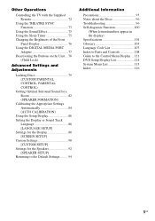
DAV-HDX500 Post (short) Bottom of the base 2 holes Speaker cord DAV-HDX501W , Top of the base (large) Post (long) Bottom of the base 2 holes Speaker cord , Top of the base (small) continued 11US Getting Started - BASIC -
DAV-HDX500 Post (short) Bottom of the base 2 holes Speaker cord DAV-HDX501W , Top of the base (large) Post (long) Bottom of the base 2 holes Speaker cord , Top of the base (small) continued 11US Getting Started - BASIC -
Operating Instructions
Page 12
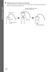
Thread the speaker cord through the hole of the post. Getting Started - BASIC - 2 Attach the post cover to the other end of the post cover. Orient the slot toward you, attach the post cover so that the slot of the post engages with the screw. Speaker cord , Hole Upper part of the post cover, then secure with the tab of the post Post cover , Screw (small, black) 12US
Thread the speaker cord through the hole of the post. Getting Started - BASIC - 2 Attach the post cover to the other end of the post cover. Orient the slot toward you, attach the post cover so that the slot of the post engages with the screw. Speaker cord , Hole Upper part of the post cover, then secure with the tab of the post Post cover , Screw (small, black) 12US

Operating Instructions
Page 13
...the rear panel of speaker matches the color tube of the post cover when placing the post. Secure 2 screws (large, with washer) in the slot of the speaker, slide the post to the end of the speaker , Mounting plate continued 13US Rear of the speaker , DAV-HDX501W Post cover Be... careful the orientation of the speaker cord. Rear of the slot, then secure the post with the mounting plate and screws. BASIC - 3 Lay the post in criss-cross pattern. DAV-HDX500 Post cover Be...
...the rear panel of speaker matches the color tube of the post cover when placing the post. Secure 2 screws (large, with washer) in the slot of the speaker, slide the post to the end of the speaker , Mounting plate continued 13US Rear of the speaker , DAV-HDX501W Post cover Be... careful the orientation of the speaker cord. Rear of the slot, then secure the post with the mounting plate and screws. BASIC - 3 Lay the post in criss-cross pattern. DAV-HDX500 Post cover Be...
Operating Instructions
Page 14
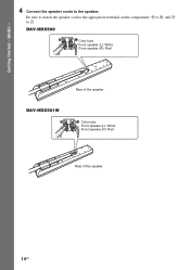
BASIC - 4 Connect the speaker cords to #. Be sure to match the speaker cord to the appropriate terminal on the components: 3 to 3, and # to the speaker. DAV-HDX500 Color tube Front speaker (L): White Front speaker (R): Red Rear of the speaker DAV-HDX501W Color tube Front speaker (L): White Front speaker (R): Red Rear of the speaker 14US Getting Started -
BASIC - 4 Connect the speaker cords to #. Be sure to match the speaker cord to the appropriate terminal on the components: 3 to 3, and # to the speaker. DAV-HDX500 Color tube Front speaker (L): White Front speaker (R): Red Rear of the speaker DAV-HDX501W Color tube Front speaker (L): White Front speaker (R): Red Rear of the speaker 14US Getting Started -
Operating Instructions
Page 16
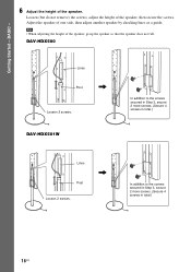
Note • When adjusting the height of one side, then adjust another speaker by checking lines as a guide. DAV-HDX500 Lines Post , Loosen 2 screws. Adjust the speaker of the speaker, grasp the speaker so that the speaker does not fall. DAV-HDX501W In addition to the screws secured in Step 3, secure 2 more screws. (Secure 4 screws in total.) Lines Post...
Note • When adjusting the height of one side, then adjust another speaker by checking lines as a guide. DAV-HDX500 Lines Post , Loosen 2 screws. Adjust the speaker of the speaker, grasp the speaker so that the speaker does not fall. DAV-HDX501W In addition to the screws secured in Step 3, secure 2 more screws. (Secure 4 screws in total.) Lines Post...

Operating Instructions
Page 17
Secure the speaker cord by pulling from the bottom of the base and hook the speaker cord in the speaker cord by running it through the slot. Adjust the length of the cord. continued 17US BASIC - 7 Take up slack in the cord clamp. Bottom of the base Adjust the length of the cord. DAV-HDX500 Take up slack in the speaker cord by running it through the slot. Getting Started - Cord clamp , Secure the speaker cord by pulling from the bottom of the base. DAV-HDX501W Take up any speaker cord slack.
Secure the speaker cord by pulling from the bottom of the base and hook the speaker cord in the speaker cord by running it through the slot. Adjust the length of the cord. continued 17US BASIC - 7 Take up slack in the cord clamp. Bottom of the base Adjust the length of the cord. DAV-HDX500 Take up slack in the speaker cord by running it through the slot. Getting Started - Cord clamp , Secure the speaker cord by pulling from the bottom of the base. DAV-HDX501W Take up any speaker cord slack.
Operating Instructions
Page 18
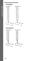
White Red DAV-HDX501W Front speaker (L): White label Front speaker (R): Red label White Red 18US BASIC - Fully-assembled illustration DAV-HDX500 Front speaker (L): White label Front speaker (R): Red label Getting Started -
White Red DAV-HDX501W Front speaker (L): White label Front speaker (R): Red label White Red 18US BASIC - Fully-assembled illustration DAV-HDX500 Front speaker (L): White label Front speaker (R): Red label Getting Started -
Operating Instructions
Page 19
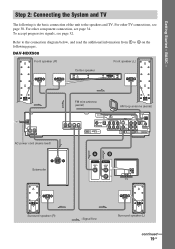
DAV-HDX500 Front speaker (R) Front speaker (L) Center speaker CENTER WOOFER SPEAKER AC power cord (mains lead) Subwoofer FM wire antenna (aerial) AM loop antenna (aerial) FRONT R FRONT L SUR R SPEAKER SUR L DIR-TC1 ... FM 75 COAXIAL ANTENNA DMPORT2 AB VIDEO IN AUDIO OUT L R TV Surround speaker (R) :Signal flow Surround speaker (L) continued 19US Refer to the connection diagram below, and read the additional information...from 1 to 4 on the following is the basic connection of the unit to the speakers and TV. For other TV connections, see page 30. Getting Started - BASIC - ...
DAV-HDX500 Front speaker (R) Front speaker (L) Center speaker CENTER WOOFER SPEAKER AC power cord (mains lead) Subwoofer FM wire antenna (aerial) AM loop antenna (aerial) FRONT R FRONT L SUR R SPEAKER SUR L DIR-TC1 ... FM 75 COAXIAL ANTENNA DMPORT2 AB VIDEO IN AUDIO OUT L R TV Surround speaker (R) :Signal flow Surround speaker (L) continued 19US Refer to the connection diagram below, and read the additional information...from 1 to 4 on the following is the basic connection of the unit to the speakers and TV. For other TV connections, see page 30. Getting Started - BASIC - ...
Operating Instructions
Page 20
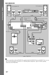
... operating instructions of the WAHT-SD1. 20US BASIC - DAV-HDX501W Front speaker (R) Center speaker Front speaker (L) CENTER WOOFER SPEAKER AC power cord (mains lead) FM wire antenna (aerial) AM loop antenna (aerial) FRONT R FRONT L SUR R SPEAKER SUR L DIR-TC1 COAXIAL OPTICAL DIGITAL IN SAT/CABLE... 75 COAXIAL ANTENNA DMPORT2 Subwoofer AB TV VIDEO IN AUDIO OUT L R Surround speaker (R) :Signal flow Surround speaker (L) Tip • When you install the wireless kit WAHT-SD1 (supplied with DAV-HDX501W only) in the DIR-TC1 slot, you can enjoy wireless performance. Getting...
... operating instructions of the WAHT-SD1. 20US BASIC - DAV-HDX501W Front speaker (R) Center speaker Front speaker (L) CENTER WOOFER SPEAKER AC power cord (mains lead) FM wire antenna (aerial) AM loop antenna (aerial) FRONT R FRONT L SUR R SPEAKER SUR L DIR-TC1 COAXIAL OPTICAL DIGITAL IN SAT/CABLE... 75 COAXIAL ANTENNA DMPORT2 Subwoofer AB TV VIDEO IN AUDIO OUT L R Surround speaker (R) :Signal flow Surround speaker (L) Tip • When you install the wireless kit WAHT-SD1 (supplied with DAV-HDX501W only) in the DIR-TC1 slot, you can enjoy wireless performance. Getting...
Operating Instructions
Page 21
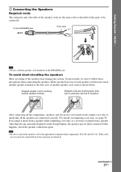
...For details on the Setup Display, the speaker may be distorted. If the cords are connected correctly. After connecting all the speakers are reversed, the sound will lack bass and may damage the system. Note • Be sure to match the speaker cord to the appropriate terminal on the ...components: 3 to 3, and # to check that all the components, speakers, and AC power cord (...
...For details on the Setup Display, the speaker may be distorted. If the cords are connected correctly. After connecting all the speakers are reversed, the sound will lack bass and may damage the system. Note • Be sure to match the speaker cord to the appropriate terminal on the ...components: 3 to 3, and # to check that all the components, speakers, and AC power cord (...

Operating Instructions
Page 22
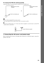
... antenna (aerial) is connected firmly by pulling softly. 22US Do not dismantle or roll up the antenna (aerial). 1 Remove only the loop part from the 6 speakers, select the "Dolby Pro Logic," "Dolby Pro Logic II MOVIE," or "Dolby Pro Logic II MUSIC" sound field (page 42). 3 Connecting the Antenna (Aerial) To...
... antenna (aerial) is connected firmly by pulling softly. 22US Do not dismantle or roll up the antenna (aerial). 1 Remove only the loop part from the 6 speakers, select the "Dolby Pro Logic," "Dolby Pro Logic II MOVIE," or "Dolby Pro Logic II MUSIC" sound field (page 42). 3 Connecting the Antenna (Aerial) To...
Operating Instructions
Page 23
... (aerial) 4 Connecting the AC power cord (mains lead) Before connecting the AC power cord (mains lead) of this unit to a wall outlet (mains), connect the speakers to fully extend the FM wire antenna (aerial). • After connecting the FM wire antenna (aerial), keep it as horizontal as shown below. Getting Started -
... (aerial) 4 Connecting the AC power cord (mains lead) Before connecting the AC power cord (mains lead) of this unit to a wall outlet (mains), connect the speakers to fully extend the FM wire antenna (aerial). • After connecting the FM wire antenna (aerial), keep it as horizontal as shown below. Getting Started -
Operating Instructions
Page 24
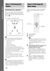
... result. • When cleaning, use any type of the speakers, it is recommended that are : - Subject to run QUICK SETUP.] appears at the same distance from the system appears on the TV screen. [Press [ENTER] to vibrations - The Setup Display for a Room" (page 82) and "...to direct sunlight • Use caution when placing the speakers and/or speaker stands that you perform the Quick Setup. Dusty or dirty - Step 3: Positioning the System Positioning the speakers For the best possible surround sound, all the speakers other than the subwoofer should be placed at the ...
... result. • When cleaning, use any type of the speakers, it is recommended that are : - Subject to run QUICK SETUP.] appears at the same distance from the system appears on the TV screen. [Press [ENTER] to vibrations - The Setup Display for a Room" (page 82) and "...to direct sunlight • Use caution when placing the speakers and/or speaker stands that you perform the Quick Setup. Dusty or dirty - Step 3: Positioning the System Positioning the speakers For the best possible surround sound, all the speakers other than the subwoofer should be placed at the ...
Operating Instructions
Page 25
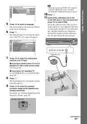
...4:3 standard TV with DAV-HDX501W only) is installed, [STANDARD (WIRELESS)] appears instead. 10 Press . 11 Connect the calibration mic to the A.CAL MIC jack on the front panel and press X/x to select [YES]. For details, see "Getting Optimal Surround Sound for selecting the speaker formation appears. 9 ... X/x to select the setting that matches your TV type. The Setup Display for a Room" (page 82). The system displays the menu and subtitles in the selected language. 6 Press . SPEAKER FORMATION Note • When the wireless kit WAHT-SD1 (supplied with a wide-screen mode [16:9] (page 88)...
...4:3 standard TV with DAV-HDX501W only) is installed, [STANDARD (WIRELESS)] appears instead. 10 Press . 11 Connect the calibration mic to the A.CAL MIC jack on the front panel and press X/x to select [YES]. For details, see "Getting Optimal Surround Sound for selecting the speaker formation appears. 9 ... X/x to select the setting that matches your TV type. The Setup Display for a Room" (page 82). The system displays the menu and subtitles in the selected language. 6 Press . SPEAKER FORMATION Note • When the wireless kit WAHT-SD1 (supplied with a wide-screen mode [16:9] (page 88)...
Operating Instructions
Page 26
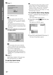
... Started - Measurement complete. The Control Menu display appears. 2 Press X/x to select press . [SETUP], then The options for [SPEAKER FORMATION], measurement of [SURROUND L] and [SURROUND R] is not displayed. 14 Press . Start measurement? See "Getting Optimal Surround Sound... R : 10ft 3.04m - 2.0dB If OK, unplug calibration mic and select "YES". To recall the Quick Setup display 1 Press DISPLAY when the system is installed may interfere with measurement. 13 Unplug the calibration mic and press C/ c to select [QUICK], then press . Note • The environment ...
... Started - Measurement complete. The Control Menu display appears. 2 Press X/x to select press . [SETUP], then The options for [SPEAKER FORMATION], measurement of [SURROUND L] and [SURROUND R] is not displayed. 14 Press . Start measurement? See "Getting Optimal Surround Sound... R : 10ft 3.04m - 2.0dB If OK, unplug calibration mic and select "YES". To recall the Quick Setup display 1 Press DISPLAY when the system is installed may interfere with measurement. 13 Unplug the calibration mic and press C/ c to select [QUICK], then press . Note • The environment ...

Operating Instructions
Page 28
...supplied) that are suitable for the hole on the back of the speaker 2 Fasten the screws to 3/8 inch) 3 Hang the speakers on the wall. For the center speaker 265 mm (10 7/16 inches) 6 to 9 mm (1/4 to 3/8 inch) For the front speakers of DAV-HDX500 6 to 9 mm (1/4 to 3/8 inch) 170 mm (6 23.../32 inches) For the front speakers of DAVHDX501W 6 to 9 mm (1/4 to 3/8 inch) 100 mm...
...supplied) that are suitable for the hole on the back of the speaker 2 Fasten the screws to 3/8 inch) 3 Hang the speakers on the wall. For the center speaker 265 mm (10 7/16 inches) 6 to 9 mm (1/4 to 3/8 inch) For the front speakers of DAV-HDX500 6 to 9 mm (1/4 to 3/8 inch) 170 mm (6 23.../32 inches) For the front speakers of DAVHDX501W 6 to 9 mm (1/4 to 3/8 inch) 100 mm...

Operating Instructions
Page 29
ADVANCED - Install the speakers on a vertical and flat wall where reinforcement is not responsible for the wall material and strength. As a plaster board wall is especially fragile, attach the screws securely to a beam and fasten them to be used. • Sony is applied. • Contact a screw shop or installer regarding the wall material or screws to the wall. Getting Started - Note • Use screws that are suitable for accident or damage caused by improper installation, insufficient wall strength or improper screw installation, natural calamity, etc. 29US
ADVANCED - Install the speakers on a vertical and flat wall where reinforcement is not responsible for the wall material and strength. As a plaster board wall is especially fragile, attach the screws securely to a beam and fasten them to be used. • Sony is applied. • Contact a screw shop or installer regarding the wall material or screws to the wall. Getting Started - Note • Use screws that are suitable for accident or damage caused by improper installation, insufficient wall strength or improper screw installation, natural calamity, etc. 29US


