
Operating Instructions (primary manual)
Page 1
SONY TRINITRON® Character Display CPD-1302 Operating Instructions page 2 Mode d'emploi page 14
SONY TRINITRON® Character Display CPD-1302 Operating Instructions page 2 Mode d'emploi page 14
Operating Instructions (primary manual)
Page 2
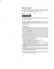
... Relocate the equipment with the manufacturer's instructions, may find the following booklet prepared by the Federal Communications Commission helpful: "How to comply with the limits for additional suggestions. This booklet is , in a residential installation. Owner's Record The model and serial numbers are present inside the unit. Do not open the cabinet. CPD-1302 Serial No. However, there is encouraged to...
... Relocate the equipment with the manufacturer's instructions, may find the following booklet prepared by the Federal Communications Commission helpful: "How to comply with the limits for additional suggestions. This booklet is , in a residential installation. Owner's Record The model and serial numbers are present inside the unit. Do not open the cabinet. CPD-1302 Serial No. However, there is encouraged to...
Operating Instructions (primary manual)
Page 3
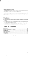
... either analog or digital RGB output to be connected. • Compatible with the Class B limits for use with microcomputers. Table of Contents Precautions 4 Location and Function of Controls 5 Connections 8 Use of the Tilt-Swivel 9 Specifications 10 Timing Charts 12 3 For the customers in Radio Interference Regulations. Features • Super Fine Pitch Trinitron character display with an anti-glaring dark screen. • An RGB terminal...
... either analog or digital RGB output to be connected. • Compatible with the Class B limits for use with microcomputers. Table of Contents Precautions 4 Location and Function of Controls 5 Connections 8 Use of the Tilt-Swivel 9 Specifications 10 Timing Charts 12 3 For the customers in Radio Interference Regulations. Features • Super Fine Pitch Trinitron character display with an anti-glaring dark screen. • An RGB terminal...
Operating Instructions (primary manual)
Page 4
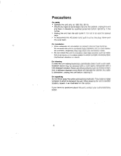
..., draperies) that may be used for several days. • To disconnect the AC power cord, pull it out by the plug. Precautions On safety •...wall outlet if it is not to be removed with a cloth lightly dampened with a soft cloth. On repacking Do not throw away the carton and packing materials. Stubborn stains may block the ventilation holes. • Do not install the unit in a location near heat sources...checked by qualified personnel before cleaning it with a mild detergent solution. On installation • Allow adequate air circulation to transport the unit. On cleaning To keep...
..., draperies) that may be used for several days. • To disconnect the AC power cord, pull it out by the plug. Precautions On safety •...wall outlet if it is not to be removed with a cloth lightly dampened with a soft cloth. On repacking Do not throw away the carton and packing materials. Stubborn stains may block the ventilation holes. • Do not install the unit in a location near heat sources...checked by qualified personnel before cleaning it with a mild detergent solution. On installation • Allow adequate air circulation to transport the unit. On cleaning To keep...

Operating Instructions (primary manual)
Page 5
The indicator will light up. For a brighter display, turn this control at the center detent position. Turn downwards to ON. EJ BRIGHTNESS control Normally keep this knob downwards, or for less contrast. To turn off the unit, press towards OFF. • ON 0 OFF [1 PICTURE control Adjusts the contrast. Location and Function of Controls 1 cr 2 3 display stand (optional) M POWER switch and indicator (green) To turn on the power of the unit, press this switch to increase contrast, or upwards for a darker display, turn it upwards. 5
The indicator will light up. For a brighter display, turn this control at the center detent position. Turn downwards to ON. EJ BRIGHTNESS control Normally keep this knob downwards, or for less contrast. To turn off the unit, press towards OFF. • ON 0 OFF [1 PICTURE control Adjusts the contrast. Location and Function of Controls 1 cr 2 3 display stand (optional) M POWER switch and indicator (green) To turn on the power of the unit, press this switch to increase contrast, or upwards for a darker display, turn it upwards. 5

Operating Instructions (primary manual)
Page 6
4 5 6 7 8 Push upward to remove panel. 9 10 H SHIFT (horizontal shift) control Turn this control to center the displays of the screen. V SIZE (vertical size) control Turn this control to adjust the horizontal size. H SIZE (horizontal size) control Turn this control to eliminate any shifting in the vertical direction. V SHIFT (vertical shift) control Turn this control to adjust the vertical size. 6 that are shifted toward the left or right side of microcomputers, character generators, etc.
4 5 6 7 8 Push upward to remove panel. 9 10 H SHIFT (horizontal shift) control Turn this control to center the displays of the screen. V SIZE (vertical size) control Turn this control to adjust the horizontal size. H SIZE (horizontal size) control Turn this control to eliminate any shifting in the vertical direction. V SHIFT (vertical shift) control Turn this control to adjust the vertical size. 6 that are shifted toward the left or right side of microcomputers, character generators, etc.
Operating Instructions (primary manual)
Page 7
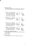
... with the supplied AC power cord. 7 puters having TTL RGB output, such as the IBM 3270. NORM-DIGITAL: For microcom- EI AC IN connector Connect to page 8. NORM D2 The position of the following four positions. I I puters having TTL RGB and I signal output, such as those using the stand- ANALOG D2-DIGITAL: For TTL graphics cards on the RGB output of the equipment you have connected, set these switches to...
... with the supplied AC power cord. 7 puters having TTL RGB output, such as the IBM 3270. NORM-DIGITAL: For microcom- EI AC IN connector Connect to page 8. NORM D2 The position of the following four positions. I I puters having TTL RGB and I signal output, such as those using the stand- ANALOG D2-DIGITAL: For TTL graphics cards on the RGB output of the equipment you have connected, set these switches to...
Operating Instructions (primary manual)
Page 8
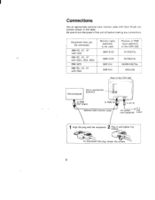
... color monitor cable to a AC power wall cord (supplied) outlet 1 Align the plug with PGA Monitor cable (optional) to be used SMF-5120 SMF-5120 SMF-514 SMF-513 Position of RGB input selectors of the CPD-1302 01-DIGITAL 02-DIGITAL NORM-DIGITAL ANALOG Microcomputer Set to turn the power of the unit off before making any connections. Qz. Plug in the table. Connections Use an appropriate optional color monitor cable with 9-pin D-sub connectors shown in and tighten the screws...
... color monitor cable to a AC power wall cord (supplied) outlet 1 Align the plug with PGA Monitor cable (optional) to be used SMF-5120 SMF-5120 SMF-514 SMF-513 Position of RGB input selectors of the CPD-1302 01-DIGITAL 02-DIGITAL NORM-DIGITAL ANALOG Microcomputer Set to turn the power of the unit off before making any connections. Qz. Plug in the table. Connections Use an appropriate optional color monitor cable with 9-pin D-sub connectors shown in and tighten the screws...
Operating Instructions (primary manual)
Page 9
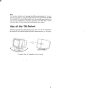
...; horizontally and 15° vertically. 15° r 90° For details, read the instructions of this unit can use your computer or character generator with CPD-1302 or which monitor cable to use, consult your authorized Sony dealer. Use of the Tilt-Swivel With the optional Sony SU-542 tilt-swivel, this unit (See page 11). Note The monitor cable should arrange the RGB output signals of...
...; horizontally and 15° vertically. 15° r 90° For details, read the instructions of this unit can use your computer or character generator with CPD-1302 or which monitor cable to use, consult your authorized Sony dealer. Use of the Tilt-Swivel With the optional Sony SU-542 tilt-swivel, this unit (See page 11). Note The monitor cable should arrange the RGB output signals of...
Operating Instructions (primary manual)
Page 10
... Vertical sync signal frequency: 50- 100 Hz Horizontal sync signal frequency: 15.0 - 34.0 kHz RGB input (D-sub 9 pin) (Analog and TTL available) 120V AC, 50/60 Hz 96 W (maximum) 360 x 300 x 425 mm (wlh/d) (141/4 x 117/8 x 163/4 inches) including projecting parts 14.5 kg (32 Ib) AC power cord (1) Optional accessories Monitor cable (9-pin - 9-pin) SM F-512C SMF-513 SMF-514 Tilt/Swivel SU-542 Display Stand Design and specifications subject to change...
... Vertical sync signal frequency: 50- 100 Hz Horizontal sync signal frequency: 15.0 - 34.0 kHz RGB input (D-sub 9 pin) (Analog and TTL available) 120V AC, 50/60 Hz 96 W (maximum) 360 x 300 x 425 mm (wlh/d) (141/4 x 117/8 x 163/4 inches) including projecting parts 14.5 kg (32 Ib) AC power cord (1) Optional accessories Monitor cable (9-pin - 9-pin) SM F-512C SMF-513 SMF-514 Tilt/Swivel SU-542 Display Stand Design and specifications subject to change...
Operating Instructions (primary manual)
Page 11
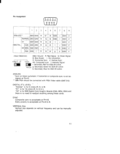
... Pin #8 & 9. H/HV V ~DIGITAL CGA GND GND R G B I 1"-- I - SYNC Composite sync is no need to readjust anything among these cards. "D2" is for EGA 64 colors ANALOG ` Sync on vertical frequency and can be connected with PGA Video cable (SMF-513) DIGITAL (TTL LEVEL) "Normal" is for 8 colors (R, G, & B) "Dl" is for 16 colors (R, G, B & I : Intensity Signal r: Secondary Red for EGA 64 colors ANALOG g: Secondary Green for EGA 64 colors b: Secondary Blue for IBM Digital Color Graphic Boards (CGA, MDA...
... Pin #8 & 9. H/HV V ~DIGITAL CGA GND GND R G B I 1"-- I - SYNC Composite sync is no need to readjust anything among these cards. "D2" is for EGA 64 colors ANALOG ` Sync on vertical frequency and can be connected with PGA Video cable (SMF-513) DIGITAL (TTL LEVEL) "Normal" is for 8 colors (R, G, & B) "Dl" is for 16 colors (R, G, B & I : Intensity Signal r: Secondary Red for EGA 64 colors ANALOG g: Secondary Green for EGA 64 colors b: Secondary Blue for IBM Digital Color Graphic Boards (CGA, MDA...

Operating Instructions (primary manual)
Page 12
Timing Charts (for approximate reference) E D2.1 (IBM CGA compatible) H-sync 4.45µs1 Horizontal 6.47µs ----I 8.03µS 63.78µs RGB input1 display period I 6.434µs V-sync Vertical 44µs 595µs. 100µs r - 16.75ms - I 44.83/is --I 18.95µs V-sync 190µs Vertical 1.64ms 2.11ms RGB input display period 12.74ms _1 3.94ms The indicated values apply when the...
Timing Charts (for approximate reference) E D2.1 (IBM CGA compatible) H-sync 4.45µs1 Horizontal 6.47µs ----I 8.03µS 63.78µs RGB input1 display period I 6.434µs V-sync Vertical 44µs 595µs. 100µs r - 16.75ms - I 44.83/is --I 18.95µs V-sync 190µs Vertical 1.64ms 2.11ms RGB input display period 12.74ms _1 3.94ms The indicated values apply when the...

Operating Instructions (primary manual)
Page 13
Ej D2-3 (IBM PGA compatible) H-sync Horizontal 4.48µs 32.7µs RGB input - 1 2.36,s---1 0.2µs V -sync Vertical 7.4µs 25.66µs 1 display period 65µs 16.65ms RGB input -I 815µs 97µs 978µs 15.672ms 1 display period The indicated values apply when the line period is 32.7µs and the field period is 16.65ms. Note The picture may be biased or the picture size may be changed depending on the timing of the connected equipment. 13
Ej D2-3 (IBM PGA compatible) H-sync Horizontal 4.48µs 32.7µs RGB input - 1 2.36,s---1 0.2µs V -sync Vertical 7.4µs 25.66µs 1 display period 65µs 16.65ms RGB input -I 815µs 97µs 978µs 15.672ms 1 display period The indicated values apply when the line period is 32.7µs and the field period is 16.65ms. Note The picture may be biased or the picture size may be changed depending on the timing of the connected equipment. 13
Warranty Card
Page 2
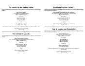
.... has established a group to supply you with technical support: Sony Technical Support URL: www.sony.com/displays/support EMAIL: [email protected] or write to : Sony of Canada Ltd. Ft. Centre de service autorisé par Sony 1-800-282-2848 Myers, FL 33913 or call: Sony Techinical Support 1-800-357-SONY (7669) For information about other Sony products in the United States...
.... has established a group to supply you with technical support: Sony Technical Support URL: www.sony.com/displays/support EMAIL: [email protected] or write to : Sony of Canada Ltd. Ft. Centre de service autorisé par Sony 1-800-282-2848 Myers, FL 33913 or call: Sony Techinical Support 1-800-357-SONY (7669) For information about other Sony products in the United States...


