
Service Manual
Page 2
...COMPOSANTS IDENTIFIÉS PAR UNE MARQUE ! NE REMPLACER CES COMPOSANTS QUE PAR DES PIÉCES SONY DONT LES NUMÉROS SONT DONNÉS DANS CE MANUEL OU DANS LES SUPPLÉMENTS PUBLIÉS PAR... Power requirements 7.2 V (battery pack) 8.4 V (AC power adaptor) Averege power consumption(when using the battery pack) During camera recording CCD-TR416/TR416PK/TR516/ TR516PK : 2.4 W CCD-TR315/TR716 : 2.5 W During camera recording using LCD CCD-TRV16/TRV16PK/TRV36/ TRV36PK : 3.1 W CCD-TRV43/TRV46/TRV46PK : 3.2 W Viewfinder CCD-TRV16/TRV16PK/TRV36/ TRV36PK : 2.5 W CCD-TRV43/TRV46/TRV46PK : 2.6...
...COMPOSANTS IDENTIFIÉS PAR UNE MARQUE ! NE REMPLACER CES COMPOSANTS QUE PAR DES PIÉCES SONY DONT LES NUMÉROS SONT DONNÉS DANS CE MANUEL OU DANS LES SUPPLÉMENTS PUBLIÉS PAR... Power requirements 7.2 V (battery pack) 8.4 V (AC power adaptor) Averege power consumption(when using the battery pack) During camera recording CCD-TR416/TR416PK/TR516/ TR516PK : 2.4 W CCD-TR315/TR716 : 2.5 W During camera recording using LCD CCD-TRV16/TRV16PK/TRV36/ TRV36PK : 3.1 W CCD-TRV43/TRV46/TRV46PK : 3.2 W Viewfinder CCD-TRV16/TRV16PK/TRV36/ TRV36PK : 2.5 W CCD-TRV43/TRV46/TRV46PK : 2.6...

Service Manual
Page 4
... abbreviated as HK. Taiwan model is abbreviated as TW. TR315//TR416PK/TR516PK CCD- TRV16:E,BR,HK,TW/TRV16PK/TRV36PK/ TRV46:E,HK/TRV46PK • Abbreviation Brazilian model is already installed in your camcorder. 5 Size AA (R6) battery for Remote Commander (2) CCD-TR516/TR516PK/TR716 CCD-TRV36/TRV36PK/TRV43/TRV46/TRV46PK 6 A / V connecting cable (1) 7 Shoulder strap (1) 8 Video P6-15P...
... abbreviated as HK. Taiwan model is abbreviated as TW. TR315//TR416PK/TR516PK CCD- TRV16:E,BR,HK,TW/TRV16PK/TRV36PK/ TRV46:E,HK/TRV46PK • Abbreviation Brazilian model is already installed in your camcorder. 5 Size AA (R6) battery for Remote Commander (2) CCD-TR516/TR516PK/TR716 CCD-TRV36/TRV36PK/TRV43/TRV46/TRV46PK 6 A / V connecting cable (1) 7 Shoulder strap (1) 8 Video P6-15P...

Service Manual
Page 5
... to prevent this unit, about 10 seconds after power is shut off so that the unit cannot operate. Battery terminal ' Method 3. to the battery terminal using adhesive tape, etc. Take note of a tape Press the battery switch of a tape. Use the DC IN terminal. (Use the AC power adaptor.) DC IN terminal... ' A 7 Let go your hold the cassette lid and rise the cassette compartment to take care not to damage) to adjust the bending of the battery terminal using the service power cord (J-6082-223-A), the power is supplied (8.4V) to remove the cabinet (L) block. 5 Add +5V from the DC POWER ...
... to prevent this unit, about 10 seconds after power is shut off so that the unit cannot operate. Battery terminal ' Method 3. to the battery terminal using adhesive tape, etc. Take note of a tape Press the battery switch of a tape. Use the DC IN terminal. (Use the AC power adaptor.) DC IN terminal... ' A 7 Let go your hold the cassette lid and rise the cassette compartment to take care not to damage) to adjust the bending of the battery terminal using the service power cord (J-6082-223-A), the power is supplied (8.4V) to remove the cabinet (L) block. 5 Add +5V from the DC POWER ...

Service Manual
Page 6
... function consists of Backup No. tion manual. and the 5-character self-diagnosis codes. E : Corrected by the coin-type lithium battery. play window what to six self-diagnosis codes shown in which the problem occurred. (If the number of problems which occurred is...time [2] : Occurred second time [5] : Occurred fifth time [3] : Occurred third time [6] : Occurred the last time 3-3. When this coin-type lithium battery is less than 6, only the number of problems which the problem occurred, and "detailed code" of previous errors Control dial 3-2. Self-diagnosis codes Order of...
... function consists of Backup No. tion manual. and the 5-character self-diagnosis codes. E : Corrected by the coin-type lithium battery. play window what to six self-diagnosis codes shown in which the problem occurred. (If the number of problems which occurred is...time [2] : Occurred second time [5] : Occurred fifth time [3] : Occurred third time [6] : Occurred the last time 3-3. When this coin-type lithium battery is less than 6, only the number of problems which the problem occurred, and "detailed code" of previous errors Control dial 3-2. Self-diagnosis codes Order of...

Service Manual
Page 7
.... C 3 2 4 0 FG fault when starting drum Load the tape again, and perform operations from the beginning. C 2 3 0 0 Non-standard battery is dirty. Loading does not C 3 1 1 0 complete within specified time Load the tape again, and perform operations from the beginning. Loading does not ... perform operations from the beginning. C 2 2 0 0 Video head is used. C 3 1 3 1 FG fault during normal capstan operations Remove the battery or power cable, connect, and perform operations from the beginning. C 3 2 4 1 PG fault when starting drum Load the tape again, and perform ...
.... C 3 2 4 0 FG fault when starting drum Load the tape again, and perform operations from the beginning. C 2 3 0 0 Non-standard battery is dirty. Loading does not C 3 1 1 0 complete within specified time Load the tape again, and perform operations from the beginning. Loading does not ... perform operations from the beginning. C 2 2 0 0 Video head is used. C 3 1 3 1 FG fault during normal capstan operations Remove the battery or power cable, connect, and perform operations from the beginning. C 3 2 4 1 PG fault when starting drum Load the tape again, and perform ...

Service Manual
Page 8
... on a TV screen 1-13 Editing onto another tape 1-13 Changing the lithium battery in the camcoder 1-13 Resetting the date and time 1-14 Simple setting of Backup...Enjoying picture effect 1-10 Adjusting the exposure 1-10 Superimposing a title 1-11 Making your camcorder abroad 1-17 Truoble check 1-17 Self-diagnosis display 1-18 Identifying the parts 1-18 Warning Indicators... Block Diagram 3-1 3-2. Mode Control Block Diagram 3-15 3-6. Service Position 2-7 2-16. Removal of CCD-TRV36/TRV43/TRV46. GENERAL This section is extacked from instruction manual of Front Panel Block and Video ...
... on a TV screen 1-13 Editing onto another tape 1-13 Changing the lithium battery in the camcoder 1-13 Resetting the date and time 1-14 Simple setting of Backup...Enjoying picture effect 1-10 Adjusting the exposure 1-10 Superimposing a title 1-11 Making your camcorder abroad 1-17 Truoble check 1-17 Self-diagnosis display 1-18 Identifying the parts 1-18 Warning Indicators... Block Diagram 3-1 3-2. Mode Control Block Diagram 3-15 3-6. Service Position 2-7 2-16. Removal of CCD-TRV36/TRV43/TRV46. GENERAL This section is extacked from instruction manual of Front Panel Block and Video ...

Service Manual
Page 10
...5-40 2-1. Input/output selection check 5-43 8. Battery End Adjustment (VC-215 board 5-45 3-3. CAP FG Offset Adjustment (VC-215 board 5-46 2. Standerd8 REC Y Current Adjustment (VC-215 board) (CCD-TR315/TR416/TR416PK CCD-TRV16/TRV16PK 5-52 9. Arrangement Diagram for adjustments 5-34 ...215 board 5-49 6. Cabinet (R) Block Assembly (TR series 6-4 6-1-5. EMG CODE (Emergency Code 5-40 2-2. Hi8 REC L Level Adjustment (VC-215 board) (CCD-TR516/TR516PK/TR716 CCD-TRV36/ TRV36PK/TRV43/TRV46/TRV46PK 5-53 10. BPF Adjustment (VC-215 board 5-59 3-7. Operating without a...
...5-40 2-1. Input/output selection check 5-43 8. Battery End Adjustment (VC-215 board 5-45 3-3. CAP FG Offset Adjustment (VC-215 board 5-46 2. Standerd8 REC Y Current Adjustment (VC-215 board) (CCD-TR315/TR416/TR416PK CCD-TRV16/TRV16PK 5-52 9. Arrangement Diagram for adjustments 5-34 ...215 board 5-49 6. Cabinet (R) Block Assembly (TR series 6-4 6-1-5. EMG CODE (Emergency Code 5-40 2-2. Hi8 REC L Level Adjustment (VC-215 board) (CCD-TR516/TR516PK/TR716 CCD-TRV36/ TRV36PK/TRV43/TRV46/TRV46PK 5-53 10. BPF Adjustment (VC-215 board 5-59 3-7. Operating without a...

Service Manual
Page 31
... LENS BLOCK VL-21/22 BOARD 2-8. DD-117 & PJ-90/91 BOARDS 2-11. BATTERY PANEL BLOCK 2-7. IR COVER (TRV series) CF-61 BOARD (TRV series) LCD PANEL (TRV series) 2-9. CONTROL SWITCH BLOCK (FK-8500) 2-10. CCD-TR315/TR416/TR416PK CCD-TRV16/TRV16PK 1Two screws (M2 x 4) 2Cabinet (LT) 1Two screws (M2x4) 2Cabinet (N) Claw 3Screw (M2...
... LENS BLOCK VL-21/22 BOARD 2-8. DD-117 & PJ-90/91 BOARDS 2-11. BATTERY PANEL BLOCK 2-7. IR COVER (TRV series) CF-61 BOARD (TRV series) LCD PANEL (TRV series) 2-9. CONTROL SWITCH BLOCK (FK-8500) 2-10. CCD-TR315/TR416/TR416PK CCD-TRV16/TRV16PK 1Two screws (M2 x 4) 2Cabinet (LT) 1Two screws (M2x4) 2Cabinet (N) Claw 3Screw (M2...

Service Manual
Page 33
REMOVAL OF BATTERY PANEL BLOCK 1Two screws (M2x4) 2Cassette lid assembly 3Connector CN801, 7P 2Battery panel block 1Two screws (M2 x 4) 2-4. REMOVAL OF CASSETTE LID ASSEMBLY 4Cabinet (R) block IR ...
REMOVAL OF BATTERY PANEL BLOCK 1Two screws (M2x4) 2Cassette lid assembly 3Connector CN801, 7P 2Battery panel block 1Two screws (M2 x 4) 2-4. REMOVAL OF CASSETTE LID ASSEMBLY 4Cabinet (R) block IR ...

Service Manual
Page 71
CF-61 BOARD (SIDE A) DATE TIME COUNTER RESET REC MODE 5SEC PUSH NOR DISPLAY TITLE END SEARCH MENU (LITHIUM BATTERY HOLDER) PICTURE EFECT SELECT-DIA 1-672-46 7 8 9 10 11 12 13 14
CF-61 BOARD (SIDE A) DATE TIME COUNTER RESET REC MODE 5SEC PUSH NOR DISPLAY TITLE END SEARCH MENU (LITHIUM BATTERY HOLDER) PICTURE EFECT SELECT-DIA 1-672-46 7 8 9 10 11 12 13 14

Service Manual
Page 82
... ND filter 1.0 ND filter 0.3 Pattern box PTB-450 Color bar chart for distinction functions of models and classification 1-1. CCD-TR315/TR416/TR416PK/TR516/TR516PK/TR716 CCD-TRV16/TRV16PK/TRV36/TRV36PK/TRV43/TRV46/TRV46PK SECTION 5 ADJUSTMENTS 5-1. PREPARATIONS BEFORE ADJUSTMENT (CAMERA SECTION) 1-1-1. Note 2: Connect the ...439-A For checking the flange back For adjusting LCD block For adjusting the video section and color viewfinder adjustment For connecting the battery terminal and DC power supply For adjusting the deviation For extension between the CD-210/211 board (CN401) and VC-215...
... ND filter 1.0 ND filter 0.3 Pattern box PTB-450 Color bar chart for distinction functions of models and classification 1-1. CCD-TR315/TR416/TR416PK/TR516/TR516PK/TR716 CCD-TRV16/TRV16PK/TRV36/TRV36PK/TRV43/TRV46/TRV46PK SECTION 5 ADJUSTMENTS 5-1. PREPARATIONS BEFORE ADJUSTMENT (CAMERA SECTION) 1-1-1. Note 2: Connect the ...439-A For checking the flange back For adjusting LCD block For adjusting the video section and color viewfinder adjustment For connecting the battery terminal and DC power supply For adjusting the deviation For extension between the CD-210/211 board (CN401) and VC-215...

Service Manual
Page 84
... CN901 CN911 CN910 CN915 CN905 CN906 CN908 MA-345 board CN303 CF-60 board CN001 Extension cable(70P) (J-6082-439-A) Battery terminal (Note 1) Regulaterd power supply (8.4 ± 0.1 Vdc) Battery switch CN935 CN934 CN801 CN931 DD-117 board Adjusting remote commander LANC terminal Must be connected when performing the VIDEO system or...jig (J-6082-382-A) Note 1: Connect the adjusting remote commander to the LANC jack, and set the HOLD switch to the "ADJ" side, or press the battery switch of the battery terminal using adhesive tape, etc. or use the AC power adaptor. Fig. 5-1-3.
... CN901 CN911 CN910 CN915 CN905 CN906 CN908 MA-345 board CN303 CF-60 board CN001 Extension cable(70P) (J-6082-439-A) Battery terminal (Note 1) Regulaterd power supply (8.4 ± 0.1 Vdc) Battery switch CN935 CN934 CN801 CN931 DD-117 board Adjusting remote commander LANC terminal Must be connected when performing the VIDEO system or...jig (J-6082-382-A) Note 1: Connect the adjusting remote commander to the LANC jack, and set the HOLD switch to the "ADJ" side, or press the battery switch of the battery terminal using adhesive tape, etc. or use the AC power adaptor. Fig. 5-1-3.

Service Manual
Page 85
... CN001 CN901 CN911 CN910 CN915 CN905 CN906 CN908 MA-346 board CN303 CF-61 board CN001 Extension cable(70P) (J-6082-439-A) Battery terminal (Note 2) Regulaterd power supply (8.4 ± 0.1 Vdc) Battery switch CN935 CN934 Adjusting remote commander LANC jack CN801 CN931 CN933 DD-117 board Must be connected when performing the LCD system... CN5802 CN5803 CN5804 Note 2 : Connect the adjusting remote commander to the LANC jack, and set the HOLD switch to the "ADJ" side, or press the battery switch of the battery terminal using adhesive tape, etc. or use the AC power adaptor.
... CN001 CN901 CN911 CN910 CN915 CN905 CN906 CN908 MA-346 board CN303 CF-61 board CN001 Extension cable(70P) (J-6082-439-A) Battery terminal (Note 2) Regulaterd power supply (8.4 ± 0.1 Vdc) Battery switch CN935 CN934 Adjusting remote commander LANC jack CN801 CN931 CN933 DD-117 board Must be connected when performing the LCD system... CN5802 CN5803 CN5804 Note 2 : Connect the adjusting remote commander to the LANC jack, and set the HOLD switch to the "ADJ" side, or press the battery switch of the battery terminal using adhesive tape, etc. or use the AC power adaptor.

Service Manual
Page 90
... 24 25 26 27 28 29 2A 00 Fixed data-1 2B 00 2C 00 2D 00 2E Fixed data-2 2F 64 Fixed data-1 30 88 Battery end adj. 31 8D 32 A8 33 BD 34 C8 35 05 Fixed data-1 36 02 37 01 38 05 39 Fixed data-2 3A (Modified...
... 24 25 26 27 28 29 2A 00 Fixed data-1 2B 00 2C 00 2D 00 2E Fixed data-2 2F 64 Fixed data-1 30 88 Battery end adj. 31 8D 32 A8 33 BD 34 C8 35 05 Fixed data-1 36 02 37 01 38 05 39 Fixed data-2 3A (Modified...

Service Manual
Page 116
...SP (WR5-5NSP) Part Code: 8-967-995-42 Note: The following adjusting instruments are used . 5-3. WR5-4NSP (8-967-995-41) • For checking Hi8 mode operations For SP (WR5-8NSE) Part Code: 8-967-995-43 For LP (WR5-8NLE) Part Code: 8-967-995-52 • For checking AFM stereo...diagrams for adjustment related parts beginning from page 5-60. 3-1. VIDEO SECTION ADJUSTMENTS When performing adjustments, refer to the "ADJ" side, or press the battery switch of the battery terminal using adhesive tape, etc. 14) Power code Part Code: J-6082-223-A 15) AFM DEV jig (J-6082-312-A) 16) IR Receiving jig ...
...SP (WR5-5NSP) Part Code: 8-967-995-42 Note: The following adjusting instruments are used . 5-3. WR5-4NSP (8-967-995-41) • For checking Hi8 mode operations For SP (WR5-8NSE) Part Code: 8-967-995-43 For LP (WR5-8NLE) Part Code: 8-967-995-52 • For checking AFM stereo...diagrams for adjustment related parts beginning from page 5-60. 3-1. VIDEO SECTION ADJUSTMENTS When performing adjustments, refer to the "ADJ" side, or press the battery switch of the battery terminal using adhesive tape, etc. 14) Power code Part Code: J-6082-223-A 15) AFM DEV jig (J-6082-312-A) 16) IR Receiving jig ...

Service Manual
Page 117
... OUT 10 REC RF 11 RF SWP 12 CAP FG 13 EVF BL 14 EVF BL 4.75V 15 VCO 16 EVF VG Table 5-3-1. cept during battery end adjustment. But removing the cabinet (R) (removing the VC-215 board CN911) means removing the lithium 3V power supply (CF-60/61 board) , data such...
... OUT 10 REC RF 11 RF SWP 12 CAP FG 13 EVF BL 14 EVF BL 4.75V 15 VCO 16 EVF VG Table 5-3-1. cept during battery end adjustment. But removing the cabinet (R) (removing the VC-215 board CN911) means removing the lithium 3V power supply (CF-60/61 board) , data such...
Service Manual
Page 118
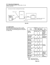
... SP AFM stereo Checking operations SP BPF adjustment Table 5-3-2. Particle type metal tape ME ..... Connecting the TV Monitor and Regulated Power Supply Battery terminal Regulated power supply 8.4±0.1Vdc Main Unit VIDEO VIDEO terminal Fig. 5-3-2. Alignment Tape The following table lists alignment tapes which are ... MP SP Operation check (SP mode) WR5-8NSE Operation check (LP mode) WR5-4NL Hi8 ME SP Standard8 MP Checking LP operations Operation check (LP mode) WR5-8NLE Hi8 ME LP AFM stereo Operation check WR5-9NS Standard8 MP BPF adjustment WR5-11NS Standard8 MP ...
... SP AFM stereo Checking operations SP BPF adjustment Table 5-3-2. Particle type metal tape ME ..... Connecting the TV Monitor and Regulated Power Supply Battery terminal Regulated power supply 8.4±0.1Vdc Main Unit VIDEO VIDEO terminal Fig. 5-3-2. Alignment Tape The following table lists alignment tapes which are ... MP SP Operation check (SP mode) WR5-8NSE Operation check (LP mode) WR5-4NL Hi8 ME SP Standard8 MP Checking LP operations Operation check (LP mode) WR5-8NLE Hi8 ME LP AFM stereo Operation check WR5-9NS Standard8 MP BPF adjustment WR5-11NS Standard8 MP ...

Service Manual
Page 120
...Select page: 0, address: 01, and set will not be recorded in the following ways. 1) Unplug the main power supply and remove the lithium battery. (In this unit switches as shown in the nonvolatile memory by users are canceled. Perform resetting.) 2) After data on adjustment Note: After the... page D and F, the data set data: 01 before setting the data of the all adjustments, cancell the ser- The playback mode (Standard 8/Hi8) switches automaticaly according to the original condition. 1. vice mode by either of the tape played back. And when data on the adjusting remote commander....
...Select page: 0, address: 01, and set will not be recorded in the following ways. 1) Unplug the main power supply and remove the lithium battery. (In this unit switches as shown in the nonvolatile memory by users are canceled. Perform resetting.) 2) After data on adjustment Note: After the... page D and F, the data set data: 01 before setting the data of the all adjustments, cancell the ser- The playback mode (Standard 8/Hi8) switches automaticaly according to the original condition. 1. vice mode by either of the tape played back. And when data on the adjusting remote commander....

Service Manual
Page 125
...) Day After setting the clock, set the bit value of use data is removed (reset). Note: This data will be erased when the coin lithium battery is displayed at page 3, addresses: A2 to "0". 9. 8.
...) Day After setting the clock, set the bit value of use data is removed (reset). Note: This data will be erased when the coin lithium battery is displayed at page 3, addresses: A2 to "0". 9. 8.

Service Manual
Page 126
...Arbitrary LCD display of the adjusting remote commander D 30 to the battery terminal as shown in Fig. 5-3-4. CAMERA SECTION ADJUSTMENT". 2. Battery End Adjustment (VC-215 board) Set the battery end voltage. The image at the battery end will shorten. Switch setting 1) AUTO FOCUS OFF 2) LCD ...the regulated power supply and the digital voltmeter to 34 Note 1: The lens block and cabinet (R) must be rough. Initialization of the battery will also be connected. Adjusting method: 1) Adjust the output voltage of the regulated power supply so that the digital voltmeter display is ...
...Arbitrary LCD display of the adjusting remote commander D 30 to the battery terminal as shown in Fig. 5-3-4. CAMERA SECTION ADJUSTMENT". 2. Battery End Adjustment (VC-215 board) Set the battery end voltage. The image at the battery end will shorten. Switch setting 1) AUTO FOCUS OFF 2) LCD ...the regulated power supply and the digital voltmeter to 34 Note 1: The lens block and cabinet (R) must be rough. Initialization of the battery will also be connected. Adjusting method: 1) Adjust the output voltage of the regulated power supply so that the digital voltmeter display is ...


