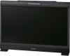
Brochure
Page 2
...) Supplied accessories AC power cord (1), AC plug holder (1), AC power cord (1), AC plug holder (1), Bracket Bracket (1), Operation Manual (Japanese, (1), Rack mount bracket (2), Operation English, each 1), CD-ROM (1), Using the Manual (Japanese, English, each 1), CD-ROM Manual (1) CD-ROM (1), Using the CD-ROM Manual (1) *1 DisplayPort will be supported from the monitor software version 1.1 or later. *2 Requires the BKM-250TG 3G-SDI input adaptor (serial number 7200001 or later), sold separately. 3D signals are not displayed...
...) Supplied accessories AC power cord (1), AC plug holder (1), AC power cord (1), AC plug holder (1), Bracket Bracket (1), Operation Manual (Japanese, (1), Rack mount bracket (2), Operation English, each 1), CD-ROM (1), Using the Manual (Japanese, English, each 1), CD-ROM Manual (1) CD-ROM (1), Using the CD-ROM Manual (1) *1 DisplayPort will be supported from the monitor software version 1.1 or later. *2 Requires the BKM-250TG 3G-SDI input adaptor (serial number 7200001 or later), sold separately. 3D signals are not displayed...

User Manual
Page 2
... the manufacturer. • Use only with the cart, stand, tripod, bracket, or table specified by the manufacturer, or sold with the manufacturer's instructions. • Do not install near water. • Clean only with a main switch on the apparatus. To avoid electrical shock, do not expose this apparatus near any heat sources such as power-supply cord or plug is required when...
... the manufacturer. • Use only with the cart, stand, tripod, bracket, or table specified by the manufacturer, or sold with the manufacturer's instructions. • Do not install near water. • Clean only with a main switch on the apparatus. To avoid electrical shock, do not expose this apparatus near any heat sources such as power-supply cord or plug is required when...

User Manual
Page 6
... Power Cord 25 Turning on the Monitor 25 Settings 26 Selecting the Area 26 Setting for the LAN to Connect the Multiple Units 27 Selecting the Monitor (Designation of the Monitor or Group ID Number 28 Assigning the Input Signal to the Channel.........28 Setting the Display Mode of the Picture 29 Adjusting 29 Chroma/Phase Adjustment 29 Color Temperature (White Balance) Adjustment 30 Brightness/Contrast Adjustment 31 Chapter 3 Menu Basic Menu Operations 32 Menu Operation Buttons 32 Displaying...
... Power Cord 25 Turning on the Monitor 25 Settings 26 Selecting the Area 26 Setting for the LAN to Connect the Multiple Units 27 Selecting the Monitor (Designation of the Monitor or Group ID Number 28 Assigning the Input Signal to the Channel.........28 Setting the Display Mode of the Picture 29 Adjusting 29 Chroma/Phase Adjustment 29 Color Temperature (White Balance) Adjustment 30 Brightness/Contrast Adjustment 31 Chapter 3 Menu Basic Menu Operations 32 Menu Operation Buttons 32 Displaying...

User Manual
Page 7
... a Function Button 97 Upgrading the Monitor and Controller...........98 Saving the Upgrade Data in a "Memory Stick PRO 98 Upgrading the Monitor 98 Upgrading the Controller 99 Appendixes Specifications 101 Input Signals and Adjustable/Setting Items 104 Available Signal Systems 106 Available Signal Formats 108 Aperture Modification Frequency 116 Picture Display Size 118 Picture Frame Display 120 Scan Mode Image 122 Troubleshooting 124 Dimensions 126 Inserting/Ejecting the "Memory Stick" ........ 128 Notes on "Memory Stick 128 Menu Index...
... a Function Button 97 Upgrading the Monitor and Controller...........98 Saving the Upgrade Data in a "Memory Stick PRO 98 Upgrading the Monitor 98 Upgrading the Controller 99 Appendixes Specifications 101 Input Signals and Adjustable/Setting Items 104 Available Signal Systems 106 Available Signal Formats 108 Aperture Modification Frequency 116 Picture Display Size 118 Picture Frame Display 120 Scan Mode Image 122 Troubleshooting 124 Dimensions 126 Inserting/Ejecting the "Memory Stick" ........ 128 Notes on "Memory Stick 128 Menu Index...

User Manual
Page 8
.... These problems are displayed in the same position on surfaces (rugs, blankets, etc.) or near heat sources such as center markers or area markers 8 Precautions This is damaged, turn off (black), always on the power cord. It is recommended for service operation. ...power cord from the wall outlet if it is not to be used in the OLED panel for its high-precision images, permanent burn-in may cause burn-in • Masked images with a power source as it any further. • Do not drop or place heavy objects on (red, green, or blue), or flashing. When installing the installation...
.... These problems are displayed in the same position on surfaces (rugs, blankets, etc.) or near heat sources such as center markers or area markers 8 Precautions This is damaged, turn off (black), always on the power cord. It is recommended for service operation. ...power cord from the wall outlet if it is not to be used in the OLED panel for its high-precision images, permanent burn-in may cause burn-in • Masked images with a power source as it any further. • Do not drop or place heavy objects on (red, green, or blue), or flashing. When installing the installation...

User Manual
Page 12
... signal. The signals are connected to confirm the color tone and picture angle of Video Electronics Standards Association. This display is useful for the picture display. For the operation, see "Capturing the Picture of the HD Signal (HD Frame Capture)" on the SDI signal is displayed by installing the optional input adaptor (BKM-250TG). 3D signal analyzing function The monitor supports the following display modes of the right (R) signal is also optimized and displayed...
... signal. The signals are connected to confirm the color tone and picture angle of Video Electronics Standards Association. This display is useful for the picture display. For the operation, see "Capturing the Picture of the HD Signal (HD Frame Capture)" on the SDI signal is displayed by installing the optional input adaptor (BKM-250TG). 3D signal analyzing function The monitor supports the following display modes of the right (R) signal is also optimized and displayed...

User Manual
Page 13
... right (R) 3D video signals are equipped. This display is useful for comparing the color or brightness of this monitor inverts the input signals to monitor signal noise. • A parallel remote of the screen, that is equipped. You can view the camera images being shot on film, using the ASC CDL function. Note The horizontal flip display function of the L and R signals, as non-inverted images. Variable picture adjustment functions Auto chroma, phase and...
... right (R) 3D video signals are equipped. This display is useful for comparing the color or brightness of this monitor inverts the input signals to monitor signal noise. • A parallel remote of the screen, that is equipped. You can view the camera images being shot on film, using the ASC CDL function. Note The horizontal flip display function of the L and R signals, as non-inverted images. Variable picture adjustment functions Auto chroma, phase and...
User Manual
Page 14
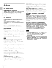
... Monitor Interface Cable Used to connect the BVM-E250 to the operating instructions of the embedded audio signals superimposed on the SDI signals are equipped. For information about the Channel Configuration menu, see "Installing an Input Adaptor" (page 20). 14 Options BKM-227W NTSC/PAL Input Adaptor Includes a decoder for serial digital component signals. BKM-243HS HD/D1-SDI Input Adaptor Includes a decoder for analog component signals and analog RGB signals. Using...
... Monitor Interface Cable Used to connect the BVM-E250 to the operating instructions of the embedded audio signals superimposed on the SDI signals are equipped. For information about the Channel Configuration menu, see "Installing an Input Adaptor" (page 20). 14 Options BKM-227W NTSC/PAL Input Adaptor Includes a decoder for serial digital component signals. BKM-243HS HD/D1-SDI Input Adaptor Includes a decoder for analog component signals and analog RGB signals. Using...

User Manual
Page 16
... Remote menu (page 69) of the controller. b OPERATE lamp When the MAIN POWER switch (on the left side panel are shorted. c OVER RANGE lamp Lights in red for initialization after the switch is turned on . (The OPERATE lamp will light.) • The monitor is changed from standby mode by the lamp" (page 17). Decrease the contrast or brightness when the OVER RANGE lamp is turned on, internal data initialization starts...
... Remote menu (page 69) of the controller. b OPERATE lamp When the MAIN POWER switch (on the left side panel are shorted. c OVER RANGE lamp Lights in red for initialization after the switch is turned on . (The OPERATE lamp will light.) • The monitor is changed from standby mode by the lamp" (page 17). Decrease the contrast or brightness when the OVER RANGE lamp is turned on, internal data initialization starts...
User Manual
Page 19
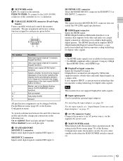
... VESA that supports both video and audio digital signals on (?), the monitor enters operation mode. DisplayPort is displayed or the monitor switches the display mode automatically between enable and disable, change pin connections in the Marker Setting menu) On/Off (MARKER button function). h Input option ports Used to the network. Chapter 1 Overview c NETWORK switch LAN: To connect to install the optional input adaptors. i AC IN connector (3-pin) Connects the monitor to display high quality digital picture. j MAIN POWER switch When turned on a single cable. Selects sync...
... VESA that supports both video and audio digital signals on (?), the monitor enters operation mode. DisplayPort is displayed or the monitor switches the display mode automatically between enable and disable, change pin connections in the Marker Setting menu) On/Off (MARKER button function). h Input option ports Used to the network. Chapter 1 Overview c NETWORK switch LAN: To connect to install the optional input adaptors. i AC IN connector (3-pin) Connects the monitor to display high quality digital picture. j MAIN POWER switch When turned on a single cable. Selects sync...

User Manual
Page 20
... apparent color reproduction on the side panel. Caution To reduce the risk of electric shock, turn off the center of the Installation Location / Installing an Input Adaptor Keep the viewing angle within 5 degrees (up/down/left/ right) off the MAIN POWER switch of the monitor and disconnect the AC power cord before installing or removing adaptors. 20 Environments of the monitor screen when the operator views the entire monitor screen.
... apparent color reproduction on the side panel. Caution To reduce the risk of electric shock, turn off the center of the Installation Location / Installing an Input Adaptor Keep the viewing angle within 5 degrees (up/down/left/ right) off the MAIN POWER switch of the monitor and disconnect the AC power cord before installing or removing adaptors. 20 Environments of the monitor screen when the operator views the entire monitor screen.

User Manual
Page 21
... used with the BKM-250TG for Dual-link operation. INPUT 1 INPUT 2 INPUT 1 INPUT 2 OPTION 1 and 2 OPTION 3 and 4 21 Installing an Input Adaptor Off 2 Insert the adaptor facing the board as shown below. Cover of the monitor. 1 Loosen two screws and remove the cover of an input option port on the side panel of an input option port Chapter 2 Preparations Make sure the MAIN POWER switch is turned off, and disconnect the AC power cord...
... used with the BKM-250TG for Dual-link operation. INPUT 1 INPUT 2 INPUT 1 INPUT 2 OPTION 1 and 2 OPTION 3 and 4 21 Installing an Input Adaptor Off 2 Insert the adaptor facing the board as shown below. Cover of the monitor. 1 Loosen two screws and remove the cover of an input option port on the side panel of an input option port Chapter 2 Preparations Make sure the MAIN POWER switch is turned off, and disconnect the AC power cord...

User Manual
Page 30
... the RGB signal. The adjusted data is confirmed. 6 Set the BLUE ONLY button to adjust the digital signal from the standard input, BKM-220D, BKM-243HS, BKM-244CC or BKM-250TG. If manual adjustment is accessed by this method, the adjusted value is common to the monitor. 2 Select Auto in the Picture Adj menu of the Adjustment menu and perform the automatic adjustment of the MANUAL button is lit. To turn off . Red and green signals...
... the RGB signal. The adjusted data is confirmed. 6 Set the BLUE ONLY button to adjust the digital signal from the standard input, BKM-220D, BKM-243HS, BKM-244CC or BKM-250TG. If manual adjustment is accessed by this method, the adjusted value is common to the monitor. 2 Select Auto in the Picture Adj menu of the Adjustment menu and perform the automatic adjustment of the MANUAL button is lit. To turn off . Red and green signals...

User Manual
Page 31
Chapter 2 Preparations Brightness/Contrast Adjustment As an image on a color video monitor is seen differently according to the ambient light (environmental brightness), adjust the brightness (black level) according to the ambient light and the black level of the controller. SD signal Adjust so that the 0% and +2% ranges are seen as equal and the +2% and +4% ranges are more distinctive. Note You can access manual adjustment without opening the Adjustment menu. To access it, press the MANUAL button located...
Chapter 2 Preparations Brightness/Contrast Adjustment As an image on a color video monitor is seen differently according to the ambient light (environmental brightness), adjust the brightness (black level) according to the ambient light and the black level of the controller. SD signal Adjust so that the 0% and +2% ranges are seen as equal and the +2% and +4% ranges are more distinctive. Note You can access manual adjustment without opening the Adjustment menu. To access it, press the MANUAL button located...

User Manual
Page 44
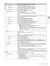
... 3 Menu Picture Adj Menu Color Bar Restore Factory Data Status Input Port Format Matrix Manual Adjust Copy From Preset Value Other Monitor Monitor ID Memory Stick Function and operation ([ ]: factory setting) Sets the color-bar signal to input. [Full Field 8]: 100% full-field 8-color bars (white, yellow, cyan, green, magenta, red, blue and black) SMPTE: SMPTE standard color bars EIA: EIA standard color bars (effective for Preset (D-Cine)) To display no characters on the screen while adjusting manually Set the...
... 3 Menu Picture Adj Menu Color Bar Restore Factory Data Status Input Port Format Matrix Manual Adjust Copy From Preset Value Other Monitor Monitor ID Memory Stick Function and operation ([ ]: factory setting) Sets the color-bar signal to input. [Full Field 8]: 100% full-field 8-color bars (white, yellow, cyan, green, magenta, red, blue and black) SMPTE: SMPTE standard color bars EIA: EIA standard color bars (effective for Preset (D-Cine)) To display no characters on the screen while adjusting manually Set the...

User Manual
Page 50
... the CIE chromaticity coordinate. External: Select when an external sync signal is used . When D-Cine is selected, the color temperature is set to the input signal. Select from D-Cine XYZ or User XYZ1 to the installed adaptor. Chapter 3 Menu Input Port Menu Input No Screen Aspect HD SD DC 2048 × 1080 HDMI Auto Sync Mode Color Temp Picture Preset Function and operation ([ ]: factory setting) Option1&2, Option3&4 • When two BKM-243HS or...
... the CIE chromaticity coordinate. External: Select when an external sync signal is used . When D-Cine is selected, the color temperature is set to the input signal. Select from D-Cine XYZ or User XYZ1 to the installed adaptor. Chapter 3 Menu Input Port Menu Input No Screen Aspect HD SD DC 2048 × 1080 HDMI Auto Sync Mode Color Temp Picture Preset Function and operation ([ ]: factory setting) Option1&2, Option3&4 • When two BKM-243HS or...

User Manual
Page 55
... images, while using the brightness or contrast adjustment, the picture may be clipped, because of the dynamic range of the brightness or contrast, to the setting value of the circuit. Sets the aperture modification value. Sets whether or not to control the signal gain automatically according to prevent such clipping (Off or [On]). 55 Auxiliary Setting Menu iAuxiliary Setting Native Scan Mode: Aperture Value: NTSC Comb Filter: Filter Switch: Peak White Control...
... images, while using the brightness or contrast adjustment, the picture may be clipped, because of the dynamic range of the brightness or contrast, to the setting value of the circuit. Sets the aperture modification value. Sets whether or not to control the signal gain automatically according to prevent such clipping (Off or [On]). 55 Auxiliary Setting Menu iAuxiliary Setting Native Scan Mode: Aperture Value: NTSC Comb Filter: Filter Switch: Peak White Control...
User Manual
Page 71
On Screen Set Menu Service 708 Service 608 OSD Level Audio Level Meter Audio CH Position Transparency Peak Hold Time Code VITC/LTC Position Level Over Range Password Change Password Function and operation ([ ]: factory setting) Sets Service when Type is set to a lower level. You can select from High (bright), or [Low] (dark). The setting is set ALM Hold Reset to on the video signal, the audio level meter may be cut partially because of the scan mode setting of...
On Screen Set Menu Service 708 Service 608 OSD Level Audio Level Meter Audio CH Position Transparency Peak Hold Time Code VITC/LTC Position Level Over Range Password Change Password Function and operation ([ ]: factory setting) Sets Service when Type is set to a lower level. You can select from High (bright), or [Low] (dark). The setting is set ALM Hold Reset to on the video signal, the audio level meter may be cut partially because of the scan mode setting of...

User Manual
Page 80
... respectively. Comb: The comb filter is turned on the display, see "Aperture Modification Frequency" on the screen. External Sync: Sets whether or not to set to monitor the analog RGB signal. Native Scan: Displays the picture in native scan mode. 16:9: Changes the aspect ratio to 16:9 or 1.896:1 (digital cinema signal), and when set to off , the signal to F16 80 Controller Menu Function and operation ([ ]: factory setting) The following functions are assigned. When...
... respectively. Comb: The comb filter is turned on the display, see "Aperture Modification Frequency" on the screen. External Sync: Sets whether or not to set to monitor the analog RGB signal. Native Scan: Displays the picture in native scan mode. 16:9: Changes the aspect ratio to 16:9 or 1.896:1 (digital cinema signal), and when set to off , the signal to F16 80 Controller Menu Function and operation ([ ]: factory setting) The following functions are assigned. When...
User Manual
Page 132
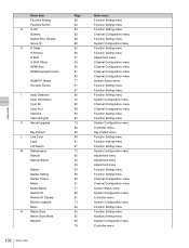
Appendixes Menu Item Function Setting Function Switch G G Off Gamma Gamut Error Display Group ID H H Delay H Position H Shift H Shift Offset HDMI Auto HDMI/DisplayPort Auto HDMI/DP Status Horopter Check I Input Detection Input Information Input No Input Port Interlace Internal Signal K Kernel Upgrade Key Protect L Line Color Load L/R Switch M Maintenance Manual Manual Adjust Marker Marker Setting Marker Preset Matrix Model Name Monitor ID Monitor ID Display Monitor Upgrade Mono N Native Scan Native Scan Mode Network 132 Menu Index Page 56 62 63 ...
Appendixes Menu Item Function Setting Function Switch G G Off Gamma Gamut Error Display Group ID H H Delay H Position H Shift H Shift Offset HDMI Auto HDMI/DisplayPort Auto HDMI/DP Status Horopter Check I Input Detection Input Information Input No Input Port Interlace Internal Signal K Kernel Upgrade Key Protect L Line Color Load L/R Switch M Maintenance Manual Manual Adjust Marker Marker Setting Marker Preset Matrix Model Name Monitor ID Monitor ID Display Monitor Upgrade Mono N Native Scan Native Scan Mode Network 132 Menu Index Page 56 62 63 ...


