
Operating Instructions
Page 4
... 3 Connections Connecting a Monitor 40 Using an i.LINK Connection 41 Settings required for an i.LINK connection 41 Making a backup of the images being recorded 41 Using the camcorder as a feeder 42 Other Connections 44 Connecting a number of camcorders ......... 44 Chapter 4 Recording and Playback Inserting a Cassette 45 Basic Procedure for Shooting 46 Recording 47 Usable cassettes 47 Selecting the recording format 49 Adjusting the black balance/white balance 50 Setting the electronic shutter 52 Adjusting the iris 55 Adjusting the audio level 57 Setting the time data 57 Setting...
... 3 Connections Connecting a Monitor 40 Using an i.LINK Connection 41 Settings required for an i.LINK connection 41 Making a backup of the images being recorded 41 Using the camcorder as a feeder 42 Other Connections 44 Connecting a number of camcorders ......... 44 Chapter 4 Recording and Playback Inserting a Cassette 45 Basic Procedure for Shooting 46 Recording 47 Usable cassettes 47 Selecting the recording format 49 Adjusting the black balance/white balance 50 Setting the electronic shutter 52 Adjusting the iris 55 Adjusting the audio level 57 Setting the time data 57 Setting...

Operating Instructions
Page 5
... settings of the camcorder to the standard settings 116 Displaying a File-Related Menu Page When Inserting a "Memory Stick" . 117 Chapter 7 Appendix Important Notes on Operation 118 Characteristics of CCD sensors 119 Maintenance 120 Cleaning the video heads 120 Replacing the video heads 120 Replacing other parts 120 Using the auto-check function 120 About i.LINK 122 About a "Memory Stick 123 Operation Warnings 125 Troubleshooting 128 Specifications 130 Chart of Optional Components and Accessories 133 Glossary 135 Index 137 5 Recording...
... settings of the camcorder to the standard settings 116 Displaying a File-Related Menu Page When Inserting a "Memory Stick" . 117 Chapter 7 Appendix Important Notes on Operation 118 Characteristics of CCD sensors 119 Maintenance 120 Cleaning the video heads 120 Replacing the video heads 120 Replacing other parts 120 Using the auto-check function 120 About i.LINK 122 About a "Memory Stick 123 Operation Warnings 125 Troubleshooting 128 Specifications 130 Chart of Optional Components and Accessories 133 Glossary 135 Index 137 5 Recording...
Operating Instructions
Page 7
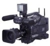
... function automatically traces the white balance, which constantly changes as ATW, VTR start/stop, etc., to make high-angle and low-angle recording easier. You can check the video image during both recording and playback. You can set shutter speed 7 Features Stylish angles and an attractive finish for shooting a particular scene as a scene file in progressive scan mode, see "Setting the CCD scan mode (DSR-450WS/450WSP only)" on recording in the internal memory...
... function automatically traces the white balance, which constantly changes as ATW, VTR start/stop, etc., to make high-angle and low-angle recording easier. You can check the video image during both recording and playback. You can set shutter speed 7 Features Stylish angles and an attractive finish for shooting a particular scene as a scene file in progressive scan mode, see "Setting the CCD scan mode (DSR-450WS/450WSP only)" on recording in the internal memory...

Operating Instructions
Page 8
... equipment supporting a digital signal interface without an adaptor. Remote control connectors (DSR-450WS/450WSP only) Instead of making film-like images. Both can be set to a higher brightness level. LP mode is useful for pool coverage, etc. You can connect other can be used in various ways; VBS video input signal (DSR-450WS/450WSP only) By installing an optional CBK-SC01 Composite Input Board, the camcorder can record in...
... equipment supporting a digital signal interface without an adaptor. Remote control connectors (DSR-450WS/450WSP only) Instead of making film-like images. Both can be set to a higher brightness level. LP mode is useful for pool coverage, etc. You can connect other can be used in various ways; VBS video input signal (DSR-450WS/450WSP only) By installing an optional CBK-SC01 Composite Input Board, the camcorder can record in...

Operating Instructions
Page 10
... "Basic menu operations" on page 52. l SHUTTER switch Set to ON to display a zebra pattern (diagonal stripes) in position. Flick to SEL to lock the lens in the viewfinder screen. When this lever to switch the shutter speed or shutter mode setting within the menu. m AUDIO LEVEL knob Adjusts the channel 1 audio input level manually. While setting the wide-band white balance, the button does not function. However, on the setting change the setting so that areas where the video level is...
... "Basic menu operations" on page 52. l SHUTTER switch Set to ON to display a zebra pattern (diagonal stripes) in position. Flick to SEL to lock the lens in the viewfinder screen. When this lever to switch the shutter speed or shutter mode setting within the menu. m AUDIO LEVEL knob Adjusts the channel 1 audio input level manually. While setting the wide-band white balance, the button does not function. However, on the setting change the setting so that areas where the video level is...

Operating Instructions
Page 11
... switch and the FILTER selector. BARS CAM OFF ON DCC OUTPUT: CAM, DCC: ON The video signal from the camera part, between the following cases. • Shooting people in speaker or earphones. ALARM Minimum Maximum h LCD monitor Displays VTR-related warnings, remaining battery capacity, remaining tape capacity, audio levels, time data, and so on the setting change /adjustment progress message display area of the viewfinder screen for about 3 seconds. j WHITE BAL (white balance memory) switch Controls adjustment of the battery...
... switch and the FILTER selector. BARS CAM OFF ON DCC OUTPUT: CAM, DCC: ON The video signal from the camera part, between the following cases. • Shooting people in speaker or earphones. ALARM Minimum Maximum h LCD monitor Displays VTR-related warnings, remaining battery capacity, remaining tape capacity, audio levels, time data, and so on the setting change /adjustment progress message display area of the viewfinder screen for about 3 seconds. j WHITE BAL (white balance memory) switch Controls adjustment of the battery...

Operating Instructions
Page 13
... audio setting switches (page 14) and make audio adjustments. The indicator lights while the tape is being rewound. Lights-out: When the cassette is in stop mode to check input signals. This can hear the alarm sound through internal electric circuits only. At this button again during playback. In E-E mode, video and audio signals input to -Electric." When an alarm is automatically muted. * E-E: Abbreviation of the lights displayed, see "Operation Warnings" on the situation. e STOP button Stops playing...
... audio setting switches (page 14) and make audio adjustments. The indicator lights while the tape is being rewound. Lights-out: When the cassette is in stop mode to check input signals. This can hear the alarm sound through internal electric circuits only. At this button again during playback. In E-E mode, video and audio signals input to -Electric." When an alarm is automatically muted. * E-E: Abbreviation of the lights displayed, see "Operation Warnings" on the situation. e STOP button Stops playing...

Operating Instructions
Page 14
... existing time code. Details on how to MANUAL. SET: Sets the time code or user bits. Use this setting when synchronizing the time code with the existing time code recorded on the tape. g F-RUN/SET/R-RUN (free run/set a new time code or to the internal clock. R-RUN: The time code value advances only during recording. AUTO: Automatic adjustment MANUAL: Manual adjustment 14 Location and Function of the F-RUN/SET/R-RUN switch, the camcorder operates in R-RUN mode. PRESET: Records a new time code. Regardless of the setting of Parts d Lithium battery compartment...
... existing time code. Details on how to MANUAL. SET: Sets the time code or user bits. Use this setting when synchronizing the time code with the existing time code recorded on the tape. g F-RUN/SET/R-RUN (free run/set a new time code or to the internal clock. R-RUN: The time code value advances only during recording. AUTO: Automatic adjustment MANUAL: Manual adjustment 14 Location and Function of the F-RUN/SET/R-RUN switch, the camcorder operates in R-RUN mode. PRESET: Records a new time code. Regardless of the setting of Parts d Lithium battery compartment...

Operating Instructions
Page 18
... cable (DV cable) and then reconnect it, making sure that it possible to a stereo amplifier or video monitor's audio input connectors. Connect to control the camcorder remotely. When synchronizing the time code of an external VTR with i.LINK connectors, turn off the power of Parts Set the input selection switches as a stereo amplifier Note If MIC +48V ON is selected for a video monitor. For details, see "Selecting the output signals (DSR-450WS...
... cable (DV cable) and then reconnect it, making sure that it possible to a stereo amplifier or video monitor's audio input connectors. Connect to control the camcorder remotely. When synchronizing the time code of an external VTR with i.LINK connectors, turn off the power of Parts Set the input selection switches as a stereo amplifier Note If MIC +48V ON is selected for a video monitor. For details, see "Selecting the output signals (DSR-450WS...

Operating Instructions
Page 22
... remaining tape recording time (in the 16:9 mode. Chapter 1 Overview b Trigger mode PARA: Operates both internal and external VTRs. EXT: Operates the external VTR only. i EXT/IV indicator (DSR-450WS/450WSP only) Displayed when a CBK-SC01 Composite Input Board is installed for three seconds in the upper and lower parts respectively. Audio channel 1 level indicator Audio channel 2 level indicator VTR level meter indicator n Operation/error message display area For details, see "Display modes and setting change confirmation/adjustment progress messages" on...
... remaining tape recording time (in the 16:9 mode. Chapter 1 Overview b Trigger mode PARA: Operates both internal and external VTRs. EXT: Operates the external VTR only. i EXT/IV indicator (DSR-450WS/450WSP only) Displayed when a CBK-SC01 Composite Input Board is installed for three seconds in the upper and lower parts respectively. Audio channel 1 level indicator Audio channel 2 level indicator VTR level meter indicator n Operation/error message display area For details, see "Display modes and setting change confirmation/adjustment progress messages" on...

Operating Instructions
Page 38
... remote control unit is output. To disable the camcorder REC button and the lens VTR button On the FUNCTION 3 page of the paint adjustment that is used are overwritten by those on the camcorder. If the REC SWITCH function is connected, using the RM REC START item on the remote control unit is connected to CAM. In this setting also enables these controls. Non-volatile memory Setup menu of the camcorder Independent data region MASTER BLACK MASTER GAMMA KNEE POINT DETAIL LEVEL...
... remote control unit is output. To disable the camcorder REC button and the lens VTR button On the FUNCTION 3 page of the paint adjustment that is used are overwritten by those on the camcorder. If the REC SWITCH function is connected, using the RM REC START item on the remote control unit is connected to CAM. In this setting also enables these controls. Non-volatile memory Setup menu of the camcorder Independent data region MASTER BLACK MASTER GAMMA KNEE POINT DETAIL LEVEL...
Operating Instructions
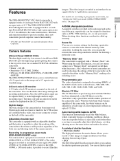
Page 41
... audio and image being recorded on the FUNCTION 3 page of the REC TRIGGER switch does not affect the internal VTR. For details, see "Usable cassettes" on the camcorder, the setting of the MAINTENANCE menu. Note When the scan mode is controlled from the camcorder. PARALLEL: Operates both the internal VTR of connection DSR-400/400P/450WS/450WSP External VTR i.LINK cable (DV cable) DSR-50/PD170, etc. External VTR operation is performed locally. Chapter 3 Connections Using...
... audio and image being recorded on the FUNCTION 3 page of the REC TRIGGER switch does not affect the internal VTR. For details, see "Usable cassettes" on the camcorder, the setting of the MAINTENANCE menu. Note When the scan mode is controlled from the camcorder. PARALLEL: Operates both the internal VTR of connection DSR-400/400P/450WS/450WSP External VTR i.LINK cable (DV cable) DSR-50/PD170, etc. External VTR operation is performed locally. Chapter 3 Connections Using...

Operating Instructions
Page 48
... tape DVCAM tape DV tape Recording format DVCAM DV • Though DV cassettes can be played back only when recorded in time code) DV format) * There are independent. To enable recording Set the REC/SAVE switch back to recorder's format as described below. Therefore, lock mode is more effective than that is available for audio recording, lock mode and unlock mode. Reel Compatibility of DVCAM and DV formats This camcorder can also use DVCAM cassettes to play back correctly. Recorder's format...
... tape DVCAM tape DV tape Recording format DVCAM DV • Though DV cassettes can be played back only when recorded in time code) DV format) * There are independent. To enable recording Set the REC/SAVE switch back to recorder's format as described below. Therefore, lock mode is more effective than that is available for audio recording, lock mode and unlock mode. Reel Compatibility of DVCAM and DV formats This camcorder can also use DVCAM cassettes to play back correctly. Recorder's format...

Operating Instructions
Page 64
... button on Auto Interval Rec mode Audio Audio fade-in/fade-out functions are input even in Interval Rec mode, you use these buttons, stop recording by setting the POWER switch to OFF or setting INTERVAL REC to a video signal when recording. For details on menu operations, see "Basic menu operations" on page 93. 19 SOURCE SEL TOP REC VIDEO SOURCE: EXT SETUP REMOVE :ON To end auto interval recording You can be recorded on . Chapter 4 Recording and Playback The camcorder starts recording in the viewfinder lights...
... button on Auto Interval Rec mode Audio Audio fade-in/fade-out functions are input even in Interval Rec mode, you use these buttons, stop recording by setting the POWER switch to OFF or setting INTERVAL REC to a video signal when recording. For details on menu operations, see "Basic menu operations" on page 93. 19 SOURCE SEL TOP REC VIDEO SOURCE: EXT SETUP REMOVE :ON To end auto interval recording You can be recorded on . Chapter 4 Recording and Playback The camcorder starts recording in the viewfinder lights...
Operating Instructions
Page 65
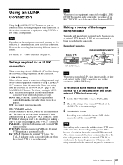
... the color video monitor Connect a color video monitor to ASSIGN switches" on the lens. Use this last part of the recording is distorted during playback. Recording Review With recording paused, press the RET button on page 106. For details about the switches and controls used to select the audio output signal and to adjust the audio level, see "Assigning functions to the MONITOR OUT connector or the VIDEO OUT connector of the MAINTENANCE menu. Notes • The video image...
... the color video monitor Connect a color video monitor to ASSIGN switches" on the lens. Use this last part of the recording is distorted during playback. Recording Review With recording paused, press the RET button on page 106. For details about the switches and controls used to select the audio output signal and to adjust the audio level, see "Assigning functions to the MONITOR OUT connector or the VIDEO OUT connector of the MAINTENANCE menu. Notes • The video image...

Operating Instructions
Page 108
... recorded image if you change the operating mode for the internal time code generator using the FRUN/SET/R-RUN switch under the AUDIO adjustment cover while recording. • The video and audio signal and time code output via i.LINK may not be noise on 2-3 pulldown • When dropframe time code is set to CLOCK, the time code is synchronized to the internal clock, and this unit operates in F-RUN and NDF mode. • When drop frame time code is input...
... recorded image if you change the operating mode for the internal time code generator using the FRUN/SET/R-RUN switch under the AUDIO adjustment cover while recording. • The video and audio signal and time code output via i.LINK may not be noise on 2-3 pulldown • When dropframe time code is set to CLOCK, the time code is synchronized to the internal clock, and this unit operates in F-RUN and NDF mode. • When drop frame time code is input...

Operating Instructions
Page 123
...; We recommend that you make a backup copy of important data that you set the "Memory Stick" erasure prevention switch to corrosive substances "Memory Stick" access indicator If the access indicator is turned on data read/write speed Data read/write speed may damage the data. Under direct sunlight - Very humid or subject to "LOCK," data cannot be recorded, edited, or erased. • Data may be used with products compliant with the MagicGate copyright...
...; We recommend that you make a backup copy of important data that you set the "Memory Stick" erasure prevention switch to corrosive substances "Memory Stick" access indicator If the access indicator is turned on data read/write speed Data read/write speed may damage the data. Under direct sunlight - Very humid or subject to "LOCK," data cannot be recorded, edited, or erased. • Data may be used with products compliant with the MagicGate copyright...

Operating Instructions
Page 127
... the error message appears again, turn off the camcorder. When the error code other than 3 seconds. 2 When the PLAY button, the REW button, and the FF button all flash at one time, release your fingers. 3 If the cassette is ejected, change the cassette because it may be damaged. However, because it may be able to eject the cassette using the following procedure. Operation/error messages An operation or error message is your responsibility. Error code list Error code Er07...
... the error message appears again, turn off the camcorder. When the error code other than 3 seconds. 2 When the PLAY button, the REW button, and the FF button all flash at one time, release your fingers. 3 If the cassette is ejected, change the cassette because it may be damaged. However, because it may be able to eject the cassette using the following procedure. Operation/error messages An operation or error message is your responsibility. Error code list Error code Er07...

Operating Instructions
Page 135
... adjustment of hue, and saturation of noise inherent to suppress certain types of a video camera and video monitor. EXT TC (External time code) A time code input from external equipment together with even rows. (Odd-row fields and evenrow fields contain images from the time code value at the beginning of time code to record time codes and audio signals that black has no color. XDCAM uses the i.LINK interface to the conventional time code recorded on tape based media...
... adjustment of hue, and saturation of noise inherent to suppress certain types of a video camera and video monitor. EXT TC (External time code) A time code input from external equipment together with even rows. (Odd-row fields and evenrow fields contain images from the time code value at the beginning of time code to record time codes and audio signals that black has no color. XDCAM uses the i.LINK interface to the conventional time code recorded on tape based media...

Operating Instructions
Page 138
... OUTPUT page 75 OUTPUT/DCC switch 11 Overview 6 P PAINT menu 80 PEAKING control 20 PLAY button and indicator 13 Playback Indicator 23 On the color video monitor 65 Recording review 65 Power supply Preparing 29 POWER switch 11 Pre-lighting function 63 PRESET WHT page 86 PRESET/REGEN/CLOCK switch 14 Product configurations 6 PsF (progressive scan) mode 107 R REC button 9 REC TRIGGER switch 15 REC/SAVE switch 48 REC/TALLY indicators 21 Recording format Indicator 22 Selecting 49 Recording shot data...
... OUTPUT page 75 OUTPUT/DCC switch 11 Overview 6 P PAINT menu 80 PEAKING control 20 PLAY button and indicator 13 Playback Indicator 23 On the color video monitor 65 Recording review 65 Power supply Preparing 29 POWER switch 11 Pre-lighting function 63 PRESET WHT page 86 PRESET/REGEN/CLOCK switch 14 Product configurations 6 PsF (progressive scan) mode 107 R REC button 9 REC TRIGGER switch 15 REC/SAVE switch 48 REC/TALLY indicators 21 Recording format Indicator 22 Selecting 49 Recording shot data...


