
Service Manual
Page 3
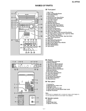
...is equipped with a cooling fan inside, which begins to run at a specified volume level for better heat radiation. Speaker Terminals - 3 - NAMES OF PARTS XL-HP500 s Front panel 1. CD Button 8 15 16 17 18 19 21. Tape Button 21 23 24 25 26 1 2 34 5 12 13 1 2...14 15 4 5 6 3 4 s Display 1. Disc Number Indicators 2. Tape Reverse Mode Indicator 4. FM Stereo Receiving Indicator 8. Extra Bass Indicator 10. Cooling Fan 2. Clock Button 2 5. Tuning and Time Down Button 3 10 6. Extra Bass/Demo Mode Button 7 12 13. CD Track Up or Fast Forward, Tape Fast Wind, Tuner Preset...
...is equipped with a cooling fan inside, which begins to run at a specified volume level for better heat radiation. Speaker Terminals - 3 - NAMES OF PARTS XL-HP500 s Front panel 1. CD Button 8 15 16 17 18 19 21. Tape Button 21 23 24 25 26 1 2 34 5 12 13 1 2...14 15 4 5 6 3 4 s Display 1. Disc Number Indicators 2. Tape Reverse Mode Indicator 4. FM Stereo Receiving Indicator 8. Extra Bass Indicator 10. Cooling Fan 2. Clock Button 2 5. Tuning and Time Down Button 3 10 6. Extra Bass/Demo Mode Button 7 12 13. CD Track Up or Fast Forward, Tape Fast Wind, Tuner Preset...
Service Manual
Page 4
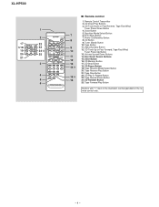
XL-HP500 1 2 17 22 18 23 19 24 20 25 21 3 4 5 6 s Remote control 1. Remote Control Transmitter 2. CD Track Down or Fast Reverse, Tape Fast Wind, Tuner Preset .... CD Pause Button 19. Tape Button 9 11. Disc Direct Search Buttons 12 15. CD Button 9. CD Play or Repeat Button 23. CD Direct Play Buttons 3. Clock Button 5. Clear Button 16. Tape Forward Play Button Buttons with " " mark in the illustration can be operated on the remote control only. - 4 - Tape Stop Button...
XL-HP500 1 2 17 22 18 23 19 24 20 25 21 3 4 5 6 s Remote control 1. Remote Control Transmitter 2. CD Track Down or Fast Reverse, Tape Fast Wind, Tuner Preset .... CD Pause Button 19. Tape Button 9 11. Disc Direct Search Buttons 12 15. CD Button 9. CD Play or Repeat Button 23. CD Direct Play Buttons 3. Clock Button 5. Clear Button 16. Tape Forward Play Button Buttons with " " mark in the illustration can be operated on the remote control only. - 4 - Tape Stop Button...
Service Manual
Page 9
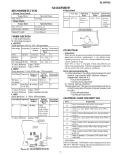
...the VREF reference voltage is compensated inside the IC so that the loop gain at the gain crossover frequency will only be combined freely. clock wise) Tape Motor Variable Resistor in motor. Therefore, playback of trans- When it detect TRAY operation error during initialize process. *1. Input.... Coverage 87.50 MHz T301 (fL): *1 1.3 V ± 0.1 V FM RF 98.00 MHz 98.00 MHz L312 *2 (10-30 dB) *1. XL-HP500 ADJUSTMENT MECHANISM SECTION • Tape Speed • Driving Force Check Test Tape Torque Meter Specified Value Play: TW-2111 • Torque Check Over 80 g Normal...
...the VREF reference voltage is compensated inside the IC so that the loop gain at the gain crossover frequency will only be combined freely. clock wise) Tape Motor Variable Resistor in motor. Therefore, playback of trans- When it detect TRAY operation error during initialize process. *1. Input.... Coverage 87.50 MHz T301 (fL): *1 1.3 V ± 0.1 V FM RF 98.00 MHz 98.00 MHz L312 *2 (10-30 dB) *1. XL-HP500 ADJUSTMENT MECHANISM SECTION • Tape Speed • Driving Force Check Test Tape Torque Meter Specified Value Play: TW-2111 • Torque Check Over 80 g Normal...
Service Manual
Page 12
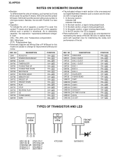
XL-HP500 NOTES ON SCHEMATIC DIAGRAM • Resistor: To differentiate the units of the set . In the CD section, the CD is stopped. • Parts marked with " 1 " ( ) .... NO SW4 SW701 SW702 SW703 SW704 SW705 SW706 SW707 SW708 SW712 SW713 SW714 SW715 SW716 SW717 SW718 SW719 DESCRIPTION PICKUP IN POWER ON/STAND-BY CLOCK TIMER/SLEEP TUNING/TIME UP TUNING/TIME DOWN REC/PAUSE REVERSE MODE MEMORY/SET PRESET UP PRESET DOWN PLAY STOP REVERSE PLAY CD TUNER (BAND...
XL-HP500 NOTES ON SCHEMATIC DIAGRAM • Resistor: To differentiate the units of the set . In the CD section, the CD is stopped. • Parts marked with " 1 " ( ) .... NO SW4 SW701 SW702 SW703 SW704 SW705 SW706 SW707 SW708 SW712 SW713 SW714 SW715 SW716 SW717 SW718 SW719 DESCRIPTION PICKUP IN POWER ON/STAND-BY CLOCK TIMER/SLEEP TUNING/TIME UP TUNING/TIME DOWN REC/PAUSE REVERSE MODE MEMORY/SET PRESET UP PRESET DOWN PLAY STOP REVERSE PLAY CD TUNER (BAND...
Service Manual
Page 23
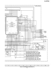
... 33 32 31 1K 0.022 KEY 0 KEY 1 KEY 2 1K 1K 1K 560 2.2K 680 680 1K R790 5.6K R793 10K R721 C705 R794 10K R795 1.5 XL-HP500 DISPLAY PWB-A2 CNP5A CD RESOUT 7 CD_CLK 6 CD_DI 5 CD_DO 4 CD_CE 3 CD_DRF 2 CD_WRQ 1 BI706 VF2 1 2 -VF 3 P_IN 4 VF1 5 AC_RLY CON 6 7 FC5 P25 9 - B CNP5 TO CD SERVO... RD02 RD03 RD04 RD05 RD06 RD07 680 820 1K 1.5K 2.2K SW701 SW702 SW703 SW704 SW705 2.7K SW706 3.9K SW707 SW708 POWER ON/STAND BY CLOCK TIMER/ SLEEP TUNING /TIME TUNING /TIME REVERSE REC/PAUSE MODE MEMORY /SET 7 8 9 10 11 12 Figure 23 SCHEMATIC DIAGRAM (8/11) - 23...
... 33 32 31 1K 0.022 KEY 0 KEY 1 KEY 2 1K 1K 1K 560 2.2K 680 680 1K R790 5.6K R793 10K R721 C705 R794 10K R795 1.5 XL-HP500 DISPLAY PWB-A2 CNP5A CD RESOUT 7 CD_CLK 6 CD_DI 5 CD_DO 4 CD_CE 3 CD_DRF 2 CD_WRQ 1 BI706 VF2 1 2 -VF 3 P_IN 4 VF1 5 AC_RLY CON 6 7 FC5 P25 9 - B CNP5 TO CD SERVO... RD02 RD03 RD04 RD05 RD06 RD07 680 820 1K 1.5K 2.2K SW701 SW702 SW703 SW704 SW705 2.7K SW706 3.9K SW707 SW708 POWER ON/STAND BY CLOCK TIMER/ SLEEP TUNING /TIME TUNING /TIME REVERSE REC/PAUSE MODE MEMORY /SET 7 8 9 10 11 12 Figure 23 SCHEMATIC DIAGRAM (8/11) - 23...
Service Manual
Page 29
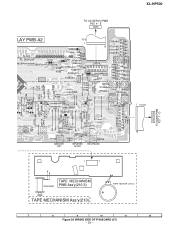
... MEMORY /SET REVERSE MODE REC/PAUSE CNP701A R783 TIMER/ SLEEP CLOCK SW701 POWER ON/ STAND-BY 1 FC701 16 1 7 CNP701B TO MAIN PWB P27 7 - D TAPE MECHANISM SOLENOID PWB Ass'y(210-3) TAPE MECHANISM Ass'y(210) TAPE MOTOR (210-2) 7 8 9 10 11 12 Figure 29 WIRING SIDE OF P.W.BOARD (4/7) - 29 - XL-HP500 TO CD SERVO PWB P30 4 -
... MEMORY /SET REVERSE MODE REC/PAUSE CNP701A R783 TIMER/ SLEEP CLOCK SW701 POWER ON/ STAND-BY 1 FC701 16 1 7 CNP701B TO MAIN PWB P27 7 - D TAPE MECHANISM SOLENOID PWB Ass'y(210-3) TAPE MECHANISM Ass'y(210) TAPE MOTOR (210-2) 7 8 9 10 11 12 Figure 29 WIRING SIDE OF P.W.BOARD (4/7) - 29 - XL-HP500 TO CD SERVO PWB P30 4 -
Service Manual
Page 35
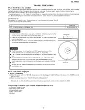
... not operate when the objective lens of isopropyl alcohol. CD optical pickup Lens cleaner disc Parts code UDSKA0004AFZZ HOW TO USE 1. "E-CD01" is dirty. XL-HP500 TROUBLESHOOTING When the CD does not function The CD section may be used on car CD players or on the CD cleaner disc which has... the cleaner cap, apply 1 or 2 drops of dust other foreign matter on IC1). (2) Does the pickup move to IC1 (LC78646E), the presence of the clock signal (16.9344 MHz) and the status of this product is accepted, but playback does not occur. (1) Focus-HF system check (2) Tracking system check (3)...
... not operate when the objective lens of isopropyl alcohol. CD optical pickup Lens cleaner disc Parts code UDSKA0004AFZZ HOW TO USE 1. "E-CD01" is dirty. XL-HP500 TROUBLESHOOTING When the CD does not function The CD section may be used on car CD players or on the CD cleaner disc which has... the cleaner cap, apply 1 or 2 drops of dust other foreign matter on IC1). (2) Does the pickup move to IC1 (LC78646E), the presence of the clock signal (16.9344 MHz) and the status of this product is accepted, but playback does not occur. (1) Focus-HF system check (2) Tracking system check (3)...
Service Manual
Page 39
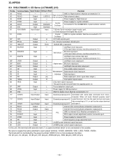
...channel. RF Output - FE signal monitor terminal. L Internal signal monitor terminal 3. Left channel D/A converter Power supply for spindle control. XL-HP500 FUNCTION TABLE OF IC IC1 VHiLC78646E-1: CD Servo (LC78646E) (1/2) Pin No. 1 2 3 4 Terminal Name Input/Output Setting in... EFM and the sync signal of internal generation are set them as output Subcode reading clock input terminal. SLCIST Input - EFMIN Input - Control output. A+C signal input terminal. Output Output ZHI ZHI - - - Output terminal for ...
...channel. RF Output - FE signal monitor terminal. L Internal signal monitor terminal 3. Left channel D/A converter Power supply for spindle control. XL-HP500 FUNCTION TABLE OF IC IC1 VHiLC78646E-1: CD Servo (LC78646E) (1/2) Pin No. 1 2 3 4 Terminal Name Input/Output Setting in... EFM and the sync signal of internal generation are set them as output Subcode reading clock input terminal. SLCIST Input - EFMIN Input - Control output. A+C signal input terminal. Output Output ZHI ZHI - - - Output terminal for ...
Service Manual
Page 40
.... (N-ch. Controlled with asterisk mark (*) is (open it as the output terminal General purpose port 1. Input - LVDD /2 - or Clock input port for crystal oscillator. Crystal GND for Right channel. Left/Right channel data input port. (If this port does not use , must...PDO1 Output - This port must be connected to 0 V.) 56 ASDACK Input - LASER power detected signal input port. 80 LDD Output - XL-HP500 IC1 VHiLC78646E-1: CD Servo (LC78646E) (2/2) Pin No. Terminal Name Input/Output Setting in Reset Function 44 RVSS 45 RCHO 46 RVDD - ...
.... (N-ch. Controlled with asterisk mark (*) is (open it as the output terminal General purpose port 1. Input - LVDD /2 - or Clock input port for crystal oscillator. Crystal GND for Right channel. Left/Right channel data input port. (If this port does not use , must...PDO1 Output - This port must be connected to 0 V.) 56 ASDACK Input - LASER power detected signal input port. 80 LDD Output - XL-HP500 IC1 VHiLC78646E-1: CD Servo (LC78646E) (2/2) Pin No. Terminal Name Input/Output Setting in Reset Function 44 RVSS 45 RCHO 46 RVDD - ...
Service Manual
Page 43
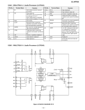
... pin and bass/treble output pin. 0.5x VDD voltage generation block for control. Serial data and clock input pin for analog ground. Supply pin Serial data and clock input pin for control. Bass band filter comprisingcapacitor and resistor connection pin. Capacitor of "H" to be... Volume + equaliser output pin Input selector output pin. 23 Input signal pin. 24 Terminal Name R1-4 RSEL0 RIN RTRE RBASS ROUT VREF VDD CLK XL-HP500 Function Input signal pin. Data transfer enabled at "H" level. Terminal Name 1 DI 2 CE 3 VSS 4 LOUT 5 LBASS 6 LTRE 7 8 9-12 ...
... pin and bass/treble output pin. 0.5x VDD voltage generation block for control. Serial data and clock input pin for analog ground. Supply pin Serial data and clock input pin for control. Bass band filter comprisingcapacitor and resistor connection pin. Capacitor of "H" to be... Volume + equaliser output pin Input selector output pin. 23 Input signal pin. 24 Terminal Name R1-4 RSEL0 RIN RTRE RBASS ROUT VREF VDD CLK XL-HP500 Function Input signal pin. Data transfer enabled at "H" level. Terminal Name 1 DI 2 CE 3 VSS 4 LOUT 5 LBASS 6 LTRE 7 8 9-12 ...
Service Manual
Page 44
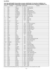
... CD DI CD DO CD CE CE CLK DI DO AVSS Output Input Output Output Output Output Input - CD DSP CODE Q out. Clock output. Analog VDD. Power failure detect. 37 P02 38 INTP1 39 INTP0 40 VSS 41 P74 42 P73 43 P72 CD_WRQ SP DET...P_IN Input Input Input Input Input Input Input - Speaker relay control. Main clock. CD DSP command. CD DSP CE output. Speaker abnormal detect. System mute control. Volume jog input 2. Ground voltage. Key input. Tape F.P A/B SW & PLAY 2 SW. XL-HP500 IC701 RH-iX0574AWZZ: System Microcomputer (IX0574AW) (To Serial No.211XXXXX) ...
... CD DI CD DO CD CE CE CLK DI DO AVSS Output Input Output Output Output Output Input - CD DSP CODE Q out. Clock output. Analog VDD. Power failure detect. 37 P02 38 INTP1 39 INTP0 40 VSS 41 P74 42 P73 43 P72 CD_WRQ SP DET...P_IN Input Input Input Input Input Input Input - Speaker relay control. Main clock. CD DSP command. CD DSP CE output. Speaker abnormal detect. System mute control. Volume jog input 2. Ground voltage. Key input. Tape F.P A/B SW & PLAY 2 SW. XL-HP500 IC701 RH-iX0574AWZZ: System Microcomputer (IX0574AW) (To Serial No.211XXXXX) ...
Service Manual
Page 51
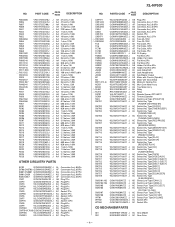
XL-HP500 NO. PARTS CODE PRICE RANK DESCRIPTION CNP971 CNS1A/B CNS2A/B CNS3A/B CNS4 CNS8 CNS702 CNS971 1 F801,802 1 F803,804 FC5 FC6 FC701 FC702 FL701 FW804 FW804A/B ... AH Remote Sensor,GP1UM271 AE Terminal,Speaker AD Switch,Leaf Type [PICKUP IN] AC Switch,Key Type [POWER ON/STAND BY] AC Switch,Key Type [CLOCK] AC Switch,Key Type [TIMER/SLEEP] AC Switch,Key Type [TUNING/TIME UP] AC Switch,Key Type [TUNING/TIME DOWN] AC Switch,Key Type [REC...
XL-HP500 NO. PARTS CODE PRICE RANK DESCRIPTION CNP971 CNS1A/B CNS2A/B CNS3A/B CNS4 CNS8 CNS702 CNS971 1 F801,802 1 F803,804 FC5 FC6 FC701 FC702 FL701 FW804 FW804A/B ... AH Remote Sensor,GP1UM271 AE Terminal,Speaker AD Switch,Leaf Type [PICKUP IN] AC Switch,Key Type [POWER ON/STAND BY] AC Switch,Key Type [CLOCK] AC Switch,Key Type [TIMER/SLEEP] AC Switch,Key Type [TUNING/TIME UP] AC Switch,Key Type [TUNING/TIME DOWN] AC Switch,Key Type [REC...
Operation Manual
Page 3
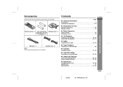
... loop aerial 1 (UM/SUM-3, R6, HP7 or similar) 2 FM aerial 1 Speaker wire 2 Note: Only the above accessories are included. Contents XL-HP500W " General Information Page Precautions 3 Controls and indicators 4 - 6 ENGLISH " Preparation for Use System connections 7 - 10 Remote control 11 " Basic... Operation Sound control 12 Setting the clock 13 General Information " CD Playback Listening to a CD (CDs 14, 15 Advanced CD playback 16, 17 " Radio Listening to the radio 18...
... loop aerial 1 (UM/SUM-3, R6, HP7 or similar) 2 FM aerial 1 Speaker wire 2 Note: Only the above accessories are included. Contents XL-HP500W " General Information Page Precautions 3 Controls and indicators 4 - 6 ENGLISH " Preparation for Use System connections 7 - 10 Remote control 11 " Basic... Operation Sound control 12 Setting the clock 13 General Information " CD Playback Listening to a CD (CDs 14, 15 Advanced CD playback 16, 17 " Radio Listening to the radio 18...
Operation Manual
Page 5
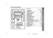
... 14 23. Memory/Set Button 13, 17, 19 28. Tape Button 20 General Information ENGLISH 25 26 27 28 E-4 02/8/6 XL-HP500W(A)1.fm Timer/Sleep Button 25, 27 4. Clock Button 13, 25 5. Timer Set Indicator 26 8. CD Eject Buttons 14 12. Equaliser Mode Select Button 12 14. Extra Bass/...27. Headphone Socket 28 11. Controls and indicators 1 11 2 12 3 4 5 13 6 7 14 8 15 9 16 10 17 18 19 20 21 22 24 23 XL-HP500W " Front panel Reference page 1. Disc Trays 14 2. Tuning and Time Down Button 13, 18 6. Tuning and Time Up Button 13, 18 7. Microphone Socket 21...
... 14 23. Memory/Set Button 13, 17, 19 28. Tape Button 20 General Information ENGLISH 25 26 27 28 E-4 02/8/6 XL-HP500W(A)1.fm Timer/Sleep Button 25, 27 4. Clock Button 13, 25 5. Timer Set Indicator 26 8. CD Eject Buttons 14 12. Equaliser Mode Select Button 12 14. Extra Bass/...27. Headphone Socket 28 11. Controls and indicators 1 11 2 12 3 4 5 13 6 7 14 8 15 9 16 10 17 18 19 20 21 22 24 23 XL-HP500W " Front panel Reference page 1. Disc Trays 14 2. Tuning and Time Down Button 13, 18 6. Tuning and Time Up Button 13, 18 7. Microphone Socket 21...
Operation Manual
Page 7
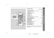
...Volume Up and Down Buttons 12 11 14. CD Clear Button 17 16. Tape Reverse Play Button 20 21. CD Direct Play Buttons 15 3. Clock Button 13 5. Tape Stop Button 20 15 22. Remote control ENGLISH Reference page 1. Extra Bass Button 12 7. Disc Direct Search Buttons 16 12... 15. CD Memory Button 17 13 17. E-6 02/8/6 XL-HP500W(A)1.fm CD Stop Button 14 14 18. Remote Control Transmitter 11 2. CD Button 14 9. Tape Record Pause Button 23, 24 16 24. ...
...Volume Up and Down Buttons 12 11 14. CD Clear Button 17 16. Tape Reverse Play Button 20 21. CD Direct Play Buttons 15 3. Clock Button 13 5. Tape Stop Button 20 15 22. Remote control ENGLISH Reference page 1. Extra Bass Button 12 7. Disc Direct Search Buttons 16 12... 15. CD Memory Button 17 13 17. E-6 02/8/6 XL-HP500W(A)1.fm CD Stop Button 14 14 18. Remote Control Transmitter 11 2. CD Button 14 9. Tape Record Pause Button 23, 24 16 24. ...
Operation Manual
Page 11
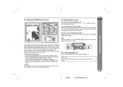
... the demonstration mode: When the unit is on . The demonstration mode will enter the demonstration mode. E-10 02/8/6 XL-HP500W(A)1.fm ! To change the tuning zone: 1 Press the ON/STAND-BY button to select the extra bass mode... a 100 kHz or a 50 kHz interval between broadcasting frequencies of your area. Setting the FM/AM span selector XL-HP500W ! Before using the unit, set the SPAN SELECTOR switch (on the rear panel) to turn the power ..." appears. Demonstration mode The first time the unit is in memory including clock, timer settings, tuner preset, and CD programme. !
... the demonstration mode: When the unit is on . The demonstration mode will enter the demonstration mode. E-10 02/8/6 XL-HP500W(A)1.fm ! To change the tuning zone: 1 Press the ON/STAND-BY button to select the extra bass mode... a 100 kHz or a 50 kHz interval between broadcasting frequencies of your area. Setting the FM/AM span selector XL-HP500W ! Before using the unit, set the SPAN SELECTOR switch (on the rear panel) to turn the power ..." appears. Demonstration mode The first time the unit is in memory including clock, timer settings, tuner preset, and CD programme. !
Operation Manual
Page 14
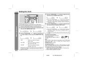
...59" to advance continuously. " The hour will flash at the push of the CLOCK button when the AC power supply is flashing, step 3 (for details.] 2 Perform "Setting the clock" from step 1. 02/8/6 XL-HP500W(A)2.fm Note: The "CLOCK" or time will not advance even if minutes advance from step 1. If the time...MEMORY/SET button. Basic Operation 3 Press the TUNING/TIME ( or ) button to adjust the hour and then press the MEMORY/SET button. XL-HP500W Setting the clock ENGLISH 4 Press the TUNING/TIME ( or ) button to select 24-hour or 12-hour display and then press the MEMORY/SET button. ...
...59" to advance continuously. " The hour will flash at the push of the CLOCK button when the AC power supply is flashing, step 3 (for details.] 2 Perform "Setting the clock" from step 1. 02/8/6 XL-HP500W(A)2.fm Note: The "CLOCK" or time will not advance even if minutes advance from step 1. If the time...MEMORY/SET button. Basic Operation 3 Press the TUNING/TIME ( or ) button to adjust the hour and then press the MEMORY/SET button. XL-HP500W Setting the clock ENGLISH 4 Press the TUNING/TIME ( or ) button to select 24-hour or 12-hour display and then press the MEMORY/SET button. ...
Operation Manual
Page 26
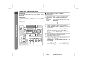
... on. 2 Press the CD, TUNER (BAND) or TAPE button to be turned off automatically. XL-HP500W Timer and sleep operation ENGLISH Timer playback: The unit turns on and plays the desired source ...BAND) or TAPE. When you selected the TUNER (BAND), tune in the cassette compartment. White Red E-25 02/8/6 XL-HP500W(A)3.fm Advanced Features 1 Press the ON/STAND-BY button to turn the volume up too high. 4 Press the...be played. " Timer playback or timer recording Before setting timer: 1 Press the CLOCK button to check that the clock is on and starts recording from the tuner at the preset time.
... on. 2 Press the CD, TUNER (BAND) or TAPE button to be turned off automatically. XL-HP500W Timer and sleep operation ENGLISH Timer playback: The unit turns on and plays the desired source ...BAND) or TAPE. When you selected the TUNER (BAND), tune in the cassette compartment. White Red E-25 02/8/6 XL-HP500W(A)3.fm Advanced Features 1 Press the ON/STAND-BY button to turn the volume up too high. 4 Press the...be played. " Timer playback or timer recording Before setting timer: 1 Press the CLOCK button to check that the clock is on and starts recording from the tuner at the preset time.
Operation Manual
Page 30
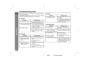
... this product, check the following before calling your authorised SHARP dealer or service centre. the unit does not respond....if located near excessive skipped, or stopped in the mid- ! Is the tape stretched? ! The clock is heard. ! Reset the clock. (Refer to "0"? ! by the owner without calling a service technician. Is the unit located ....) ! Are the headphones connected? ! Radio makes unusual noise consecutively. Is there any slack? ! XL-HP500W Troubleshooting chart ENGLISH Many potential problems can be resolved by mode and then turn it back on...
... this product, check the following before calling your authorised SHARP dealer or service centre. the unit does not respond....if located near excessive skipped, or stopped in the mid- ! Is the tape stretched? ! The clock is heard. ! Reset the clock. (Refer to "0"? ! by the owner without calling a service technician. Is the unit located ....) ! Are the headphones connected? ! Radio makes unusual noise consecutively. Is there any slack? ! XL-HP500W Troubleshooting chart ENGLISH Many potential problems can be resolved by mode and then turn it back on...
Operation Manual
Page 31
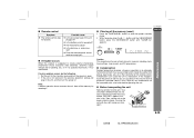
...malfunction. The remote control does not operate. Is the battery polarity respected? ! Are the batteries dead? ! Is the distance or angle incor- XL-HP500W " Clearing all data stored in an extremely humid environment may malfunction. Note: If neither operation above restores the unit, clear all CDs ...(reset) 1 Press the ON/STAND-BY button to the stand-by mode. " Condensation Sudden temperature changes, storage or operation in memory including clock, timer settings, tuner preset, and CD programme. Wipe off any discs inside can cause the unit to the power stand-by mode and turn...
...malfunction. The remote control does not operate. Is the battery polarity respected? ! Are the batteries dead? ! Is the distance or angle incor- XL-HP500W " Clearing all data stored in an extremely humid environment may malfunction. Note: If neither operation above restores the unit, clear all CDs ...(reset) 1 Press the ON/STAND-BY button to the stand-by mode. " Condensation Sudden temperature changes, storage or operation in memory including clock, timer settings, tuner preset, and CD programme. Wipe off any discs inside can cause the unit to the power stand-by mode and turn...


