
Service Manual
Page 1
... those specified be used . SY298XLHP500/ MICRO COMPONENT SYSTEM MODEL XL-HP500 XL-HP500 Micro Component System consisting of XL-HP500 (main unit) and CP-HP500 (speaker system). • In the interests of user-safety the set should be restored to its original condition and only parts identical to be used for after sales service only. ONLY) ...2 SPECIFICATIONS ...2 NAMES OF PARTS ...3 DISASSEMBLY ...5 REMOVING AND REINSTALLING THE MAIN PARTS ...7 ADJUSTMENT ...9 NOTES ON SCHEMATIC DIAGRAM ...12 TYPES...
... those specified be used . SY298XLHP500/ MICRO COMPONENT SYSTEM MODEL XL-HP500 XL-HP500 Micro Component System consisting of XL-HP500 (main unit) and CP-HP500 (speaker system). • In the interests of user-safety the set should be restored to its original condition and only parts identical to be used for after sales service only. ONLY) ...2 SPECIFICATIONS ...2 NAMES OF PARTS ...3 DISASSEMBLY ...5 REMOVING AND REINSTALLING THE MAIN PARTS ...7 ADJUSTMENT ...9 NOTES ON SCHEMATIC DIAGRAM ...12 TYPES...
Service Manual
Page 2
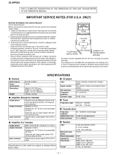
... mm) 13.2 lbs. (6.0 kg) s Amplifier (Except for Canada) Output power Output terminals Input terminals 50 watts minimum RMS per volt, or higher, sensitivity to 20 kHz, 10% total harmonic distortion Speakers: 6 ohms Headphones: 16 - 50 ohms (recommended: 32 ohms) Subwoofer pre-out (audio signal): 200 mV/ 10 k ohms at 70 Hz Video/Auxiliary (audio signal): 500 mV/47 k ohms Type Signal readout D/A converter Frequency response Dynamic range 3-disc multi-play compact disc changer player Non-contact, 3-beam semiconductor...
... mm) 13.2 lbs. (6.0 kg) s Amplifier (Except for Canada) Output power Output terminals Input terminals 50 watts minimum RMS per volt, or higher, sensitivity to 20 kHz, 10% total harmonic distortion Speakers: 6 ohms Headphones: 16 - 50 ohms (recommended: 32 ohms) Subwoofer pre-out (audio signal): 200 mV/ 10 k ohms at 70 Hz Video/Auxiliary (audio signal): 500 mV/47 k ohms Type Signal readout D/A converter Frequency response Dynamic range 3-disc multi-play compact disc changer player Non-contact, 3-beam semiconductor...
Service Manual
Page 3
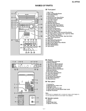
... with a cooling fan inside, which begins to run at a specified volume level for better heat radiation. Bass Reflex Duct 4. FM Stereo Receiving Indicator 8. Extra Bass/Demo Mode Button 7 12 13. Tape Reverse Play Button 13 16. Tuner (Band) Button 22 26. Tape Reverse Mode Indicator 4. FM/AM Loop Antenna Jack 5. Power On/Stand-by Button 3. CD Play Indicator 3. Disc Trays 1 2. Equalizer Mode Select Button 6 12. Speaker Terminals - 3 - s Speaker system 1. NAMES OF PARTS XL-HP500 s Front panel 1. Volume Control 14. Tuning and Time Down Button 3 10 6.
... with a cooling fan inside, which begins to run at a specified volume level for better heat radiation. Bass Reflex Duct 4. FM Stereo Receiving Indicator 8. Extra Bass/Demo Mode Button 7 12 13. Tape Reverse Play Button 13 16. Tuner (Band) Button 22 26. Tape Reverse Mode Indicator 4. FM/AM Loop Antenna Jack 5. Power On/Stand-by Button 3. CD Play Indicator 3. Disc Trays 1 2. Equalizer Mode Select Button 6 12. Speaker Terminals - 3 - s Speaker system 1. NAMES OF PARTS XL-HP500 s Front panel 1. Volume Control 14. Tuning and Time Down Button 3 10 6.
Service Manual
Page 4
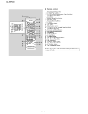
... remote control only. - 4 - CD Track Up or Fast Forward, Tape Fast Wind, Tuner Preset Up Button 13. Volume Up and Down Buttons 11 14. CD Play or Repeat Button 23. Tape Button 9 11. CD Memory Button 13 17. Tape Stop Button 15 22. Disc Direct Search Buttons 12 15. Tape Record Pause Button 16 24. Remote Control Transmitter 2. Equalizer Mode Select Button 7 6. Tape Reverse Mode Select Button 20. XL-HP500 1 2 17 22 18 23 19 24 20 25 21 3 4 5 6 s Remote control 1. CD Direct Play Buttons 3. CD Random Button...
... remote control only. - 4 - CD Track Up or Fast Forward, Tape Fast Wind, Tuner Preset Up Button 13. Volume Up and Down Buttons 11 14. CD Play or Repeat Button 23. Tape Button 9 11. CD Memory Button 13 17. Tape Stop Button 15 22. Disc Direct Search Buttons 12 15. Tape Record Pause Button 16 24. Remote Control Transmitter 2. Equalizer Mode Select Button 7 6. Tape Reverse Mode Select Button 20. XL-HP500 1 2 17 22 18 23 19 24 20 25 21 3 4 5 6 s Remote control 1. CD Direct Play Buttons 3. CD Random Button...
Service Manual
Page 9
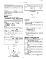
... Display Adjusting Connection Parts AM IF 450 kHz 1,602 kHz T351 *1 AM Band - Input: Antenna Output: TP301 • FM RF Signal generator: 1 kHz, 40 kHz dev., FM modulated Test Stage Frequency Frequency Display Setting/ Instrument Adjusting Connection Point FM Band - Input: Antenna Output: Speaker terminal • FM IF Signal generator: 10.7 MHz, FM modulated Test Stage Frequency Frequency Display Setting/ Instrument Adjusting Connection Point IF 10.7 MHz 98 MHz T302 *1 (Turn the core of each disc can be displayed when error...
... Display Adjusting Connection Parts AM IF 450 kHz 1,602 kHz T351 *1 AM Band - Input: Antenna Output: TP301 • FM RF Signal generator: 1 kHz, 40 kHz dev., FM modulated Test Stage Frequency Frequency Display Setting/ Instrument Adjusting Connection Point FM Band - Input: Antenna Output: Speaker terminal • FM IF Signal generator: 10.7 MHz, FM modulated Test Stage Frequency Frequency Display Setting/ Instrument Adjusting Connection Point IF 10.7 MHz 98 MHz T302 *1 (Turn the core of each disc can be displayed when error...
Service Manual
Page 10
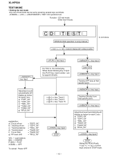
..." key input. CENTER P.GEQ - key input. IL isn't done buttons make pick's slide possible. Tracking OFF play at that specific point. XL-HP500 TEST MODE • Setting the test mode Any one of test mode can be appoint directly. key input. CD TEST OPEN/CLOSE operation is input into PLAY key, track number can be in STOP mode. When these following key is using manual. FLAT X-BASS - key input. OFF To cancel : Power OFF key input. key input. Function: -CD test mode. -Enter test 4 mode.
..." key input. CENTER P.GEQ - key input. IL isn't done buttons make pick's slide possible. Tracking OFF play at that specific point. XL-HP500 TEST MODE • Setting the test mode Any one of test mode can be appoint directly. key input. CD TEST OPEN/CLOSE operation is input into PLAY key, track number can be in STOP mode. When these following key is using manual. FLAT X-BASS - key input. OFF To cancel : Power OFF key input. key input. Function: -CD test mode. -Enter test 4 mode.
Service Manual
Page 12
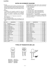
... is ohm-type resistor. As to replace these parts with no signal given. 1. In the deck section, a tape is being played back. 4. NO SW720 SW721 SW722 SW723 SW724 SW725 SW726 SW727 SW728 SWB101 SWB102 SWB103 SWB104 SWB105 SWB106 SWB107 SWB108 DESCRIPTION VIDEO/AUX DISC 3 EJECT DISC 2 EJECT DISC 1 EJECT DISC 1 DISC 2 DISC 3 EQUALIZER X-BASS/DEMO CAM 1 CAM 2 CAM 3 CAM 4 CD EJECT CD TRAY CLOSE CD IN CD SET POSITION...
... is ohm-type resistor. As to replace these parts with no signal given. 1. In the deck section, a tape is being played back. 4. NO SW720 SW721 SW722 SW723 SW724 SW725 SW726 SW727 SW728 SWB101 SWB102 SWB103 SWB104 SWB105 SWB106 SWB107 SWB108 DESCRIPTION VIDEO/AUX DISC 3 EJECT DISC 2 EJECT DISC 1 EJECT DISC 1 DISC 2 DISC 3 EQUALIZER X-BASS/DEMO CAM 1 CAM 2 CAM 3 CAM 4 CD EJECT CD TRAY CLOSE CD IN CD SET POSITION...
Service Manual
Page 23
... SW717 SW718 SW719 SW720 PRESET PRESET PLAY REVERSE STOP PLAY CD TUNER (BAND) TAPE VIDEO /AUX RD01 RD02 RD03 RD04 RD05 RD06 RD07 680 820 1K 1.5K 2.2K SW701 SW702 SW703 SW704 SW705 2.7K SW706 3.9K SW707 SW708 POWER ON/STAND BY CLOCK TIMER/ SLEEP TUNING /TIME TUNING /TIME REVERSE REC/PAUSE MODE MEMORY /SET 7 8 9 10 11 12 Figure 23 SCHEMATIC DIAGRAM (8/11) - 23 - MIC SW R737 R736...
... SW717 SW718 SW719 SW720 PRESET PRESET PLAY REVERSE STOP PLAY CD TUNER (BAND) TAPE VIDEO /AUX RD01 RD02 RD03 RD04 RD05 RD06 RD07 680 820 1K 1.5K 2.2K SW701 SW702 SW703 SW704 SW705 2.7K SW706 3.9K SW707 SW708 POWER ON/STAND BY CLOCK TIMER/ SLEEP TUNING /TIME TUNING /TIME REVERSE REC/PAUSE MODE MEMORY /SET 7 8 9 10 11 12 Figure 23 SCHEMATIC DIAGRAM (8/11) - 23 - MIC SW R737 R736...
Service Manual
Page 39
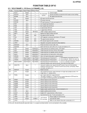
... 38 VDD Output Output Output Output Output Output - Digital system power terminal. 39* DOUT 40 TEST 41 LVDD 42 LCHO 43 LVSS Output Input Input Output - RF internal signal monitor terminal. LVDD/2 - Left channel output. SLCIST Input - RF power terminal. Capacitor connection terminal for Left channel. When not used , connect to 0 V. - GND for jitter detection. XL-HP500 FUNCTION TABLE OF IC IC1 VHiLC78646E-1: CD Servo (LC78646E) (1/2) Pin No. 1 2 3 4 Terminal Name Input/Output Setting in EFM and the sync signal of internal...
... 38 VDD Output Output Output Output Output Output - Digital system power terminal. 39* DOUT 40 TEST 41 LVDD 42 LCHO 43 LVSS Output Input Input Output - RF internal signal monitor terminal. LVDD/2 - Left channel output. SLCIST Input - RF power terminal. Capacitor connection terminal for Left channel. When not used , connect to 0 V. - GND for jitter detection. XL-HP500 FUNCTION TABLE OF IC IC1 VHiLC78646E-1: CD Servo (LC78646E) (1/2) Pin No. 1 2 3 4 Terminal Name Input/Output Setting in EFM and the sync signal of internal...
Service Manual
Page 40
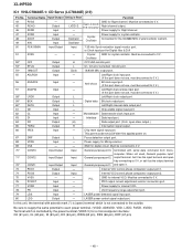
... VCO control phase comparator output port 1. 74 PDO2 Output Input Internal VCO control phase comparator output port 2. 75 VVSS 76 PCKIST - - VCO frequency range adjustment port. 79 LDS Input - Right channel output. Power supply for the 33.8688 MHz crystal oscillator ciement. 50 FSX/16MIN Input/Output Input 7.35 kHz Synchronization signal monitor port. In this port does not use , must be connect to 0 V. 70* CONT3 71* CONT2 72* CONT1 Input/Output Input/Output Input/Output Input Input Input...
... VCO control phase comparator output port 1. 74 PDO2 Output Input Internal VCO control phase comparator output port 2. 75 VVSS 76 PCKIST - - VCO frequency range adjustment port. 79 LDS Input - Right channel output. Power supply for the 33.8688 MHz crystal oscillator ciement. 50 FSX/16MIN Input/Output Input 7.35 kHz Synchronization signal monitor port. In this port does not use , must be connect to 0 V. 70* CONT3 71* CONT2 72* CONT1 Input/Output Input/Output Input/Output Input Input Input...
Service Manual
Page 51
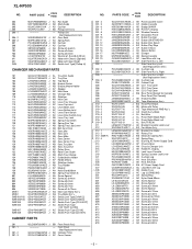
... [PLAY] AC Switch,Key Type [STOP] AC Switch,Key Type [REVERSE PLAY] AC Switch,Key Type [CD] AC Switch,Key Type [TUNER (BAND)] AC Switch,Key Type [TAPE] AC Switch,Key Type [VIDEO/AUX] AC Switch,Key Type [DISC 3 EJECT] AC Switch,Key Type [DISC 2 EJECT] AC Switch,Key Type [DISC 1 EJECT] AC Switch,Key Type [DISC 1] AC Switch,Key Type [DISC 2] AC Switch,Key Type [DISC 3] AC Switch,Key Type [EQUALIZER] AC Switch,Key Type [X-BASS/DEMO] AD Switch...
... [PLAY] AC Switch,Key Type [STOP] AC Switch,Key Type [REVERSE PLAY] AC Switch,Key Type [CD] AC Switch,Key Type [TUNER (BAND)] AC Switch,Key Type [TAPE] AC Switch,Key Type [VIDEO/AUX] AC Switch,Key Type [DISC 3 EJECT] AC Switch,Key Type [DISC 2 EJECT] AC Switch,Key Type [DISC 1 EJECT] AC Switch,Key Type [DISC 1] AC Switch,Key Type [DISC 2] AC Switch,Key Type [DISC 3] AC Switch,Key Type [EQUALIZER] AC Switch,Key Type [X-BASS/DEMO] AD Switch...
Service Manual
Page 52
...Switch AB Spring,Disc Top AB Spring,Tray Lock Lever AB Belt,Cam Drive AC Gear,Idler AB Gear,Cam AB Gear,Midle AC Gear,Center AB Gear,Center Tray AB Gear,Tray Idler AB Gear,Tray Drive AC Pulley,Drive AB Rollar,Cam Guide AB Shaft,Tray Change AC Guide... J AK Panel,Cassette Cover AF Holder,Cassette AD Badge,SHARP AG Panel,FL Display AD Window,Cassette AP Decoration Panel AF Button,Function AF Button,ON/STAND-BY AG Button,Disc Select AG Button,Play/Stop AF Button,X-Bass AC Spacer,Button AD Damper AB Spring,Cassette AC Lead Wire with Lug AP Side Panel Ass'y ,Left - XL-HP500 NO.
...Switch AB Spring,Disc Top AB Spring,Tray Lock Lever AB Belt,Cam Drive AC Gear,Idler AB Gear,Cam AB Gear,Midle AC Gear,Center AB Gear,Center Tray AB Gear,Tray Idler AB Gear,Tray Drive AC Pulley,Drive AB Rollar,Cam Guide AB Shaft,Tray Change AC Guide... J AK Panel,Cassette Cover AF Holder,Cassette AD Badge,SHARP AG Panel,FL Display AD Window,Cassette AP Decoration Panel AF Button,Function AF Button,ON/STAND-BY AG Button,Disc Select AG Button,Play/Stop AF Button,X-Bass AC Spacer,Button AD Damper AB Spring,Cassette AC Lead Wire with Lug AP Side Panel Ass'y ,Left - XL-HP500 NO.
Service Manual
Page 53
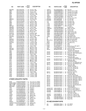
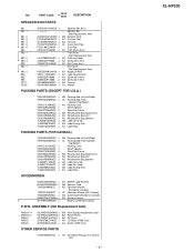
... J AK AM/FM Loop Antenna AM Speaker Cord AQ Operation Manual [Except for Canada] AF Operation Manual [For Canada] AG Quick Guide [Except for Canada] AS Remote Control Battery Lid,Remote Control P.W.B. PART CODE PRICE RANK DESCRIPTION SPEAKER BOX PARTS 901 901- 1 901- ...Display/Headphones/Jack BG Power/Power BE CD Servo AD CD Motor (PWB Only) AC Switch (PWB Only) OTHER SERVICE PARTS UDSKA0004AFZZ J AZ CD Optical Pickup Lens Cleaner Disc - 6 - XL-HP500 Speaker Box (Not Replacement Item) AM Network Cord AC Cushion,Foot AG Terminal AL Cover,Duct Pipe Duct Pipe AV Front Panel...
... J AK AM/FM Loop Antenna AM Speaker Cord AQ Operation Manual [Except for Canada] AF Operation Manual [For Canada] AG Quick Guide [Except for Canada] AS Remote Control Battery Lid,Remote Control P.W.B. PART CODE PRICE RANK DESCRIPTION SPEAKER BOX PARTS 901 901- 1 901- ...Display/Headphones/Jack BG Power/Power BE CD Servo AD CD Motor (PWB Only) AC Switch (PWB Only) OTHER SERVICE PARTS UDSKA0004AFZZ J AZ CD Optical Pickup Lens Cleaner Disc - 6 - XL-HP500 Speaker Box (Not Replacement Item) AM Network Cord AC Cushion,Foot AG Terminal AL Cover,Duct Pipe Duct Pipe AV Front Panel...
Operation Manual
Page 6
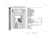
... Terminal 7, 8 7. Timer Recording Indicator 11. XL-HP500W Controls and indicators (continued) ENGLISH 1 2 34 5 6 78 9 10 11 12 13 14 15 General Information 5 6 7 8 1 9 2 3 10 4 1 3 2 4 E-5 " Display 1. AC Power Lead 7, 9 5. " Speaker system 1. FM Stereo Mode Indicator 7. FM 75 Ohms Aerial Terminal 7, 8 6. Video/Auxiliary (Audio Signal) Input Sockets 27 9. Woofer 3. CD Play Indicator 3. Span Selector Switch 10 10. Bass Reflex Duct 4. Extra Bass Indicator 10. Sleep Indicator " Rear panel Reference page 1. Cooling Fan 3.
... Terminal 7, 8 7. Timer Recording Indicator 11. XL-HP500W Controls and indicators (continued) ENGLISH 1 2 34 5 6 78 9 10 11 12 13 14 15 General Information 5 6 7 8 1 9 2 3 10 4 1 3 2 4 E-5 " Display 1. AC Power Lead 7, 9 5. " Speaker system 1. FM Stereo Mode Indicator 7. FM 75 Ohms Aerial Terminal 7, 8 6. Video/Auxiliary (Audio Signal) Input Sockets 27 9. Woofer 3. CD Play Indicator 3. Span Selector Switch 10 10. Bass Reflex Duct 4. Extra Bass Indicator 10. Sleep Indicator " Rear panel Reference page 1. Cooling Fan 3.
Operation Manual
Page 11
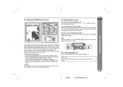
... AL" appears. To turn the power on the rear panel) as follows. Setting the FM/AM span selector XL-HP500W ! To change the tuning zone: 1 Press the ON/STAND-BY button to enter the power stand-by mode, press the X-BASS/ DEMO button again. Demonstration mode The first time the unit is in memory including clock, timer settings, tuner preset, and CD programme. ! Preparation for AM station. After use: Press the ON...
... AL" appears. To turn the power on the rear panel) as follows. Setting the FM/AM span selector XL-HP500W ! To change the tuning zone: 1 Press the ON/STAND-BY button to enter the power stand-by mode, press the X-BASS/ DEMO button again. Demonstration mode The first time the unit is in memory including clock, timer settings, tuner preset, and CD programme. ! Preparation for AM station. After use: Press the ON...
Operation Manual
Page 20
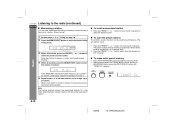
... the TUNER (BAND) button and the X- Store the stations in memory, in order, starting with preset channel 1. 4 Within 30 seconds, press the MEMORY/SET button to select the desired station. 1 Perform steps 1 - 3 in memory and recall them at the push of a button. (Preset tuning) ! The preset number will flash and the programmed stations will be a power failure or the AC power lead disconnection. Note: The backup function protects the memorised stations for...
... the TUNER (BAND) button and the X- Store the stations in memory, in order, starting with preset channel 1. 4 Within 30 seconds, press the MEMORY/SET button to select the desired station. 1 Perform steps 1 - 3 in memory and recall them at the push of a button. (Preset tuning) ! The preset number will flash and the programmed stations will be a power failure or the AC power lead disconnection. Note: The backup function protects the memorised stations for...
Operation Manual
Page 22
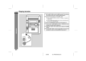
... impedance of the audio source using the VOLUME control. 6 Turn the MIC LEVEL control towards MAX to increase the microphone volume and towards MIN to the MIC socket. ! Use a microphone with a 3.5 mm (1/8") diameter plug. 3 Press the ON/STAND-BY button to turn the power on. 4 Press the CD, TUNER (BAND), TAPE or VIDEO/AUX button to select the audio source and play it. 5 Adjust the volume of 600 ohms. ! Karaoke E-21 02/8/6 XL-HP500W(A)3.fm XL-HP500W Playing karaoke ENGLISH 1 Set the MIC LEVEL control to MIN to protect...
... impedance of the audio source using the VOLUME control. 6 Turn the MIC LEVEL control towards MAX to increase the microphone volume and towards MIN to the MIC socket. ! Use a microphone with a 3.5 mm (1/8") diameter plug. 3 Press the ON/STAND-BY button to turn the power on. 4 Press the CD, TUNER (BAND), TAPE or VIDEO/AUX button to select the audio source and play it. 5 Adjust the volume of 600 ohms. ! Karaoke E-21 02/8/6 XL-HP500W(A)3.fm XL-HP500W Playing karaoke ENGLISH 1 Set the MIC LEVEL control to MIN to protect...
Operation Manual
Page 26
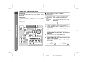
... preset time. Timer recording: The unit turns on and starts recording from the tuner at the preset time. Load a cassette or discs to the desired station. 3 Adjust the volume using the VOLUME control. back: For timer recording: Load a cassette for timer recording. When you selected the TUNER (BAND), tune in the cassette compartment. Do not turn the power on time. 2 For timer play- To select the timer playback source: CD, TUNER (BAND) or TAPE. Display...
... preset time. Timer recording: The unit turns on and starts recording from the tuner at the preset time. Load a cassette or discs to the desired station. 3 Adjust the volume using the VOLUME control. back: For timer recording: Load a cassette for timer recording. When you selected the TUNER (BAND), tune in the cassette compartment. Do not turn the power on time. 2 For timer play- To select the timer playback source: CD, TUNER (BAND) or TAPE. Display...
Operation Manual
Page 28
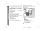
... The connection lead is displayed. E-27 02/8/6 XL-HP500W(A)3.fm When using video equipment, connect the audio output to turn the power on. 3 Press the VIDEO/AUX button. 4 Play the connected equipment. XL-HP500W Timer and sleep operation (continued) ENGLISH " Sleep operation 1 Play back the desired sound source. 2 Press the TIMER/SLEEP button repeatedly until "SLEEP" is not included. The volume will enter the power stand-by mode automat- Red White White To the line output sockets Red...
... The connection lead is displayed. E-27 02/8/6 XL-HP500W(A)3.fm When using video equipment, connect the audio output to turn the power on. 3 Press the VIDEO/AUX button. 4 Play the connected equipment. XL-HP500W Timer and sleep operation (continued) ENGLISH " Sleep operation 1 Play back the desired sound source. 2 Press the TIMER/SLEEP button repeatedly until "SLEEP" is not included. The volume will enter the power stand-by mode automat- Red White White To the line output sockets Red...
Operation Manual
Page 29
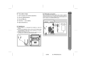
... the VIDEO/AUX button. 3 Press the button. 4 Press the / ( ) or button. 5 Play the VCR, DVD, etc. ENGLISH Speaker with a built-in amplifier to this unit, you can enjoy sound with a built-in amplifier is 32 ohms. ! Before plugging in amplifier Advanced Features 02/8/6 XL-HP500W(A)3.fm E-28 The recommended impedance is connected to the SUBWOOFER socket. Adjust the volume using the VOLUME control. Connect an RCA lead from a commercially available speaker with emphasised bass. Be sure...
... the VIDEO/AUX button. 3 Press the button. 4 Press the / ( ) or button. 5 Play the VCR, DVD, etc. ENGLISH Speaker with a built-in amplifier to this unit, you can enjoy sound with a built-in amplifier is 32 ohms. ! Before plugging in amplifier Advanced Features 02/8/6 XL-HP500W(A)3.fm E-28 The recommended impedance is connected to the SUBWOOFER socket. Adjust the volume using the VOLUME control. Connect an RCA lead from a commercially available speaker with emphasised bass. Be sure...


