
Service Manual
Page 1
ONLY) SHARP CORPORATION This document has been published to be used for after sales service only. CONTENTS Page IMPORTANT SERVICE NOTES (FOR U.S.A. The contents are subject to those specified be used . XL-HP500 SERVICE MANUAL No. ONLY) ...2 SPECIFICATIONS ...2 NAMES OF PARTS ...3 DISASSEMBLY ...5 ...PARTS LIST/EXPLODED VIEW PACKING OF THE SET (FOR U.S.A. SY298XLHP500/ MICRO COMPONENT SYSTEM MODEL XL-HP500 XL-HP500 Micro Component System consisting of XL-HP500 (main unit) and CP-HP500 (speaker system). • In the interests of user-safety the set should be restored to its...
ONLY) SHARP CORPORATION This document has been published to be used for after sales service only. CONTENTS Page IMPORTANT SERVICE NOTES (FOR U.S.A. The contents are subject to those specified be used . XL-HP500 SERVICE MANUAL No. ONLY) ...2 SPECIFICATIONS ...2 NAMES OF PARTS ...3 DISASSEMBLY ...5 ...PARTS LIST/EXPLODED VIEW PACKING OF THE SET (FOR U.S.A. SY298XLHP500/ MICRO COMPONENT SYSTEM MODEL XL-HP500 XL-HP500 Micro Component System consisting of XL-HP500 (main unit) and CP-HP500 (speaker system). • In the interests of user-safety the set should be restored to its...
Service Manual
Page 2
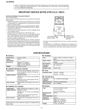
... (recording/playback) 0.3 % (WRMS) s Amplifier (For Canada) Output power Output terminals Input terminals RMS: 100 W (50 W + 50 W) (10 % T.H.D.) Speakers: 6 ohms Headphones: 16 - 50 ohms (recommended: 32 ohms) Subwoofer pre-output (audio signal): 200 mV/10 k ohms at 70 Hz Video/Auxiliary (audio signal...across the resistor. ONLY) BEFORE RETURNING THE AUDIO PRODUCT (Fire & Shock Hazard) Before returning the audio product to 0.2 milliamp. XL-HP500 FOR A COMPLETE DESCRIPTION OF THE OPERATION OF THIS UNIT, PLEASE REFER TO THE OPERATION MANUAL. Inspect all exposed metal parts having ...
... (recording/playback) 0.3 % (WRMS) s Amplifier (For Canada) Output power Output terminals Input terminals RMS: 100 W (50 W + 50 W) (10 % T.H.D.) Speakers: 6 ohms Headphones: 16 - 50 ohms (recommended: 32 ohms) Subwoofer pre-output (audio signal): 200 mV/10 k ohms at 70 Hz Video/Auxiliary (audio signal...across the resistor. ONLY) BEFORE RETURNING THE AUDIO PRODUCT (Fire & Shock Hazard) Before returning the audio product to 0.2 milliamp. XL-HP500 FOR A COMPLETE DESCRIPTION OF THE OPERATION OF THIS UNIT, PLEASE REFER TO THE OPERATION MANUAL. Inspect all exposed metal parts having ...
Service Manual
Page 3
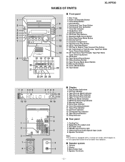
... 4 s Display 1. FM Stereo Mode Indicator 7. Sleep Indicator s Rear panel 1. Subwoofer Pre-output Jack 3. Video/Auxiliary (Audio Signal) Input Jacks 6. Speaker Terminals - 3 - Timer/Sleep Button 9 4. Timer Set Indicator 8. Volume Control 14. Tape Record Pause Button 22. Tape Forward Play Indicator 6. CD ...Compartment 15. Memory/Set Button 25. Cooling Fan 2. Disc Trays 1 2. Tape Reverse Play Indicator 5. NAMES OF PARTS XL-HP500 s Front panel 1. Bass Reflex Duct 4. Equalizer Mode Select Button 6 12. Extra Bass Indicator 10. CD Track Up...
... 4 s Display 1. FM Stereo Mode Indicator 7. Sleep Indicator s Rear panel 1. Subwoofer Pre-output Jack 3. Video/Auxiliary (Audio Signal) Input Jacks 6. Speaker Terminals - 3 - Timer/Sleep Button 9 4. Timer Set Indicator 8. Volume Control 14. Tape Record Pause Button 22. Tape Forward Play Indicator 6. CD ...Compartment 15. Memory/Set Button 25. Cooling Fan 2. Disc Trays 1 2. Tape Reverse Play Indicator 5. NAMES OF PARTS XL-HP500 s Front panel 1. Bass Reflex Duct 4. Equalizer Mode Select Button 6 12. Extra Bass Indicator 10. CD Track Up...
Service Manual
Page 9
...error. Can't detect CAM switch when CAM is 20* moving . When it detect CAM operation error during normal IC302 22* operation. XL-HP500 ADJUSTMENT MECHANISM SECTION • Tape Speed • Driving Force Check Test Tape Torque Meter Specified Value Play: TW-2111 • Torque... Adjusting Connection Parts AM IF 450 kHz 1,602 kHz T351 *1 AM Band - Input: Antenna Output: TP302 *2. Input: Antenna Output: Speaker terminal • FM IF Signal generator: 10.7 MHz, FM modulated Test Stage Frequency Frequency Display Setting/ Instrument Adjusting Connection Point IF 10...
...error. Can't detect CAM switch when CAM is 20* moving . When it detect CAM operation error during normal IC302 22* operation. XL-HP500 ADJUSTMENT MECHANISM SECTION • Tape Speed • Driving Force Check Test Tape Torque Meter Specified Value Play: TW-2111 • Torque... Adjusting Connection Parts AM IF 450 kHz 1,602 kHz T351 *1 AM Band - Input: Antenna Output: TP302 *2. Input: Antenna Output: Speaker terminal • FM IF Signal generator: 10.7 MHz, FM modulated Test Stage Frequency Frequency Display Setting/ Instrument Adjusting Connection Point IF 10...
Service Manual
Page 11
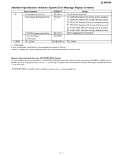
...irregular process occur on power supply line. - 11 - Speaker abnormal detection and +B PROTECTION display In case speaker abnormal detection or +B PROTECTION had occurred, it can be displayed when error had been detected for the 5th times. XL-HP500 Standard Specification of 'ER-CD**' . 'ER-CD**'... display will show "S** B**". S is referring to speaker abnormal detection and B is referring to +B PROTECTION. ** is in hex valve. +B PROTECTION...
...irregular process occur on power supply line. - 11 - Speaker abnormal detection and +B PROTECTION display In case speaker abnormal detection or +B PROTECTION had occurred, it can be displayed when error had been detected for the 5th times. XL-HP500 Standard Specification of 'ER-CD**' . 'ER-CD**'... display will show "S** B**". S is referring to speaker abnormal detection and B is referring to +B PROTECTION. ** is in hex valve. +B PROTECTION...
Service Manual
Page 15
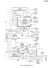
... M971(212-3) M FAN MOTOR IC901 STK402-071 POWER AMP. L1 R 15 13 7 L-OUT 10 R-OUT 89 Q901~ Q904 SP RELAY ON-OFF Q905 RL914 SO901 SPEAKER TERMINAL +B3 JK951 HEADPHONES JK953 SUB WOOFER -B2 IC851 KIA7812AP F802 CONSTANT 4A 125V VOLTAGE +B2 REGULATOR D802 F801 4A 125V M_+12.6V +B3... RELAY DRIVER D842~ D845 PT841 SUB POWER TRANSFORMER Figure 15 BLOCK DIAGRAM (3/3) - 15 - RL841 VF1 -VF VF2 AC POWER SUPPLY CORD AC 120 V, 60 Hz XL-HP500 Q603 Q604 SYSTEM MUTE C/PLAY BIAS FL701 FL DISPLAY 1 5 ~ 12 13 15 ~ 19 29 ~ 34 35 ~41 14 45 +B9 Q701 +B10 TO CD SECTION...
... M971(212-3) M FAN MOTOR IC901 STK402-071 POWER AMP. L1 R 15 13 7 L-OUT 10 R-OUT 89 Q901~ Q904 SP RELAY ON-OFF Q905 RL914 SO901 SPEAKER TERMINAL +B3 JK951 HEADPHONES JK953 SUB WOOFER -B2 IC851 KIA7812AP F802 CONSTANT 4A 125V VOLTAGE +B2 REGULATOR D802 F801 4A 125V M_+12.6V +B3... RELAY DRIVER D842~ D845 PT841 SUB POWER TRANSFORMER Figure 15 BLOCK DIAGRAM (3/3) - 15 - RL841 VF1 -VF VF2 AC POWER SUPPLY CORD AC 120 V, 60 Hz XL-HP500 Q603 Q604 SYSTEM MUTE C/PLAY BIAS FL701 FL DISPLAY 1 5 ~ 12 13 15 ~ 19 29 ~ 34 35 ~41 14 45 +B9 Q701 +B10 TO CD SECTION...
Service Manual
Page 17
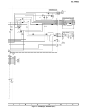
...Figure 17 SCHEMATIC DIAGRAM (2/11) - 17 - A CNP801 TO POWER PWB 801 1 2 3 4 5 6 6V 7 +B 8 LUG902(229) CHASSIS GND CNS801 1 2 3 4 5 6 7 XL-HP500 Q906 KTC3203 Y WT902 + D912 DS1SS133 MAIN PWB-A1(1/3) C930 47/50 2 2 1 1 M971 FAN MOTOR (212-3) M R949 1K (1/2W) CNP971 CNS971 R947 15K C931 10/50 +B ... FW903 JACK PWB-A4 1 R965 8.2K (1/2W) 2 R966 3 8.2K (1/2W) JK953 SUB WOOFER WT904 R967 680 (1/2W) C960 3.3/25 + L-CH + R-CH SO901 SPEAKERS 6 OHMS MIN - L-CH_GND - +B L R C927 0.22 (ML) R941 4.7 (1/2W) C929 0.22 (ML) RL914 R945 2.2K R944 2.2K R_OUT L_OUT D911 DS1SS133 ...
...Figure 17 SCHEMATIC DIAGRAM (2/11) - 17 - A CNP801 TO POWER PWB 801 1 2 3 4 5 6 6V 7 +B 8 LUG902(229) CHASSIS GND CNS801 1 2 3 4 5 6 7 XL-HP500 Q906 KTC3203 Y WT902 + D912 DS1SS133 MAIN PWB-A1(1/3) C930 47/50 2 2 1 1 M971 FAN MOTOR (212-3) M R949 1K (1/2W) CNP971 CNS971 R947 15K C931 10/50 +B ... FW903 JACK PWB-A4 1 R965 8.2K (1/2W) 2 R966 3 8.2K (1/2W) JK953 SUB WOOFER WT904 R967 680 (1/2W) C960 3.3/25 + L-CH + R-CH SO901 SPEAKERS 6 OHMS MIN - L-CH_GND - +B L R C927 0.22 (ML) R941 4.7 (1/2W) C929 0.22 (ML) RL914 R945 2.2K R944 2.2K R_OUT L_OUT D911 DS1SS133 ...
Service Manual
Page 44
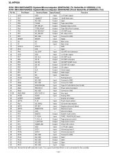
...USE NO USE Output Input Open Open In this unit, the terminal with asterisk mark (*) is (open) terminal which is not connected to GND. Speaker relay control. Connect to GND. Reset. 11 X2 12 X1 13 VPP/IC 14* XT2 15 P04 16 VDD 17 P27 X2 X1 VPP/IC... TIMER LED VDD JOG 1 JOG 2 NO USE NO USE NO USE Output Output Input Input Input Input Output Output Tape motor control. Volume jog input 2. XL-HP500 IC701 RH-iX0574AWZZ: System Microcomputer (IX0574AW) (To Serial No.211XXXXX) (1/2) IC701 RH-iX0578AWZZ: System Microcomputer (IX0578AW) (From Serial No.212XXXXX) (1/2) Pin No. Port ...
...USE NO USE Output Input Open Open In this unit, the terminal with asterisk mark (*) is (open) terminal which is not connected to GND. Speaker relay control. Connect to GND. Reset. 11 X2 12 X1 13 VPP/IC 14* XT2 15 P04 16 VDD 17 P27 X2 X1 VPP/IC... TIMER LED VDD JOG 1 JOG 2 NO USE NO USE NO USE Output Output Input Input Input Input Output Output Tape motor control. Volume jog input 2. XL-HP500 IC701 RH-iX0574AWZZ: System Microcomputer (IX0574AW) (To Serial No.211XXXXX) (1/2) IC701 RH-iX0578AWZZ: System Microcomputer (IX0578AW) (From Serial No.212XXXXX) (1/2) Pin No. Port ...
Service Manual
Page 47
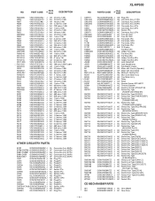
...SHARP Parts Distributor to replace parts with " " are important for the electrolytic capacitors, error is ±20%. The 13th character represents error. ("J" ±5%, "F" ±1%, "D" ±0.5%.) If there are no indications for other parts, the resistors are no indications for maintaining the safety of XL-HP500 (main unit) and CP-HP500 (speaker... system). MODEL NUMBER 2. PARTS GUIDE XL-HP500 MICRO COMPONENT SYSTEM MODEL XL-HP500 XL-HP500 Micro Component System consisting of the set . PART ...
...SHARP Parts Distributor to replace parts with " " are important for the electrolytic capacitors, error is ±20%. The 13th character represents error. ("J" ±5%, "F" ±1%, "D" ±0.5%.) If there are no indications for other parts, the resistors are no indications for maintaining the safety of XL-HP500 (main unit) and CP-HP500 (speaker... system). MODEL NUMBER 2. PARTS GUIDE XL-HP500 MICRO COMPONENT SYSTEM MODEL XL-HP500 XL-HP500 Micro Component System consisting of the set . PART ...
Service Manual
Page 51
... [Sled] AM Motor,Air Cooling Fan AQ Main Cam Motor Ass'y AQ Tray Motor Ass'y AH Relay AK Relay AH Remote Sensor,GP1UM271 AE Terminal,Speaker AD Switch,Leaf Type [PICKUP IN] AC Switch,Key Type [POWER ON/STAND BY] AC Switch,Key Type [CLOCK] AC Switch,Key Type [TIMER/SLEEP... SET] AF Switch,Push Type [VOLUME] AC Socket,5Pin AC Socket,3Pin CD MECHANISM PARTS 301 NGERH0011AWZZ J AC Gear,Middle 302 NGERH0012AWZZ J AC Gear,Drive - 4 - XL-HP500 NO.
... [Sled] AM Motor,Air Cooling Fan AQ Main Cam Motor Ass'y AQ Tray Motor Ass'y AH Relay AK Relay AH Remote Sensor,GP1UM271 AE Terminal,Speaker AD Switch,Leaf Type [PICKUP IN] AC Switch,Key Type [POWER ON/STAND BY] AC Switch,Key Type [CLOCK] AC Switch,Key Type [TIMER/SLEEP... SET] AF Switch,Push Type [VOLUME] AC Socket,5Pin AC Socket,3Pin CD MECHANISM PARTS 301 NGERH0011AWZZ J AC Gear,Middle 302 NGERH0012AWZZ J AC Gear,Drive - 4 - XL-HP500 NO.
Service Manual
Page 53
... (Not Replacement Item) AM Network Cord AC Cushion,Foot AG Terminal AL Cover,Duct Pipe Duct Pipe AV Front Panel Ass'y - NO. XL-HP500 PART CODE PRICE RANK DESCRIPTION SPEAKER BOX PARTS 901 901- 1 901- 2 901- 3 901- 4 901- 5 901- 6 902 902- 1 902- 2 902- 3 903 903- 1 903- 2 ...Flame (Not Replacement Item) AD Badge,SHARP AC Label,Specification AA Screw,ø3×10mm AA Screw,ø4×12mm AR Tweeter AY Woofer PACKING PARTS (EXCEPT FOR U.S.A.) SPAKA0395AWZZ J AM Packing Add.,Unit,Left/Right SPAKA0396AWZZ J AL Packing,Add.,Front Speaker,Top/Bottom SPAKC1510AWZZ J AU Packing ...
... (Not Replacement Item) AM Network Cord AC Cushion,Foot AG Terminal AL Cover,Duct Pipe Duct Pipe AV Front Panel Ass'y - NO. XL-HP500 PART CODE PRICE RANK DESCRIPTION SPEAKER BOX PARTS 901 901- 1 901- 2 901- 3 901- 4 901- 5 901- 6 902 902- 1 902- 2 902- 3 903 903- 1 903- 2 ...Flame (Not Replacement Item) AD Badge,SHARP AC Label,Specification AA Screw,ø3×10mm AA Screw,ø4×12mm AR Tweeter AY Woofer PACKING PARTS (EXCEPT FOR U.S.A.) SPAKA0395AWZZ J AM Packing Add.,Unit,Left/Right SPAKA0396AWZZ J AL Packing,Add.,Front Speaker,Top/Bottom SPAKC1510AWZZ J AU Packing ...

Service Manual
Page 57
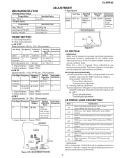
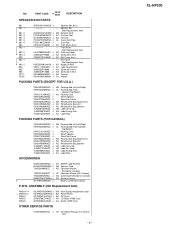
XL-HP500 A TWEETER SP1(L-CH) SP2(R-CH) Capacitor 2.2µ,100V WOOFER B SP3(L-CH) SP4(R-CH) 902 902-3x2 C 902-1 902-2x2 TWEETER SP1(L-CH) SP2(R-CH) RED Capacitor 2.2µ,100V BK RED BK WOOFER SP3(L-CH) SP4(R-CH) 901 901-2 D 902-2x2 902-3x2 E 903-2 903-1 903 SP1,2 F 905x2 SP3,4 906x4 G 901-1 901-5 901-6 904 901-4 901-3x4 H 1 2 3 4 5 6 Figure 10 SPEAKER EXPLODED VIEW - 10 -
XL-HP500 A TWEETER SP1(L-CH) SP2(R-CH) Capacitor 2.2µ,100V WOOFER B SP3(L-CH) SP4(R-CH) 902 902-3x2 C 902-1 902-2x2 TWEETER SP1(L-CH) SP2(R-CH) RED Capacitor 2.2µ,100V BK RED BK WOOFER SP3(L-CH) SP4(R-CH) 901 901-2 D 902-2x2 902-3x2 E 903-2 903-1 903 SP1,2 F 905x2 SP3,4 906x4 G 901-1 901-5 901-6 904 901-4 901-3x4 H 1 2 3 4 5 6 Figure 10 SPEAKER EXPLODED VIEW - 10 -
Service Manual
Page 58
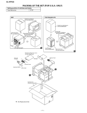
... Label,Serial No. TLABN0100AWZZ Bottom Front Speaker(L/R) Polyethylene Bag,Speaker SSAKH0099AWZZ Packing,Add., Front Speaker,Top/Bottom SPAKA0396AWZZ Label,Pop TLABZ1340AWZZ A Sheet,Speaker SPAKZ0963AWZZ Sheet,Net Frame SPAKZ1005AWZZ B Polyethylene Bag,Accessories SSAKA0007AWZZ AM Loop Antenna Speaker Cord Remote Control Operation Manual Quick Guide B A Packing Case SPAKC1510AWZZ : Not Replacement Item - 11 - XL-HP500 PACKING OF THE SET (FOR U.S.A.
... Label,Serial No. TLABN0100AWZZ Bottom Front Speaker(L/R) Polyethylene Bag,Speaker SSAKH0099AWZZ Packing,Add., Front Speaker,Top/Bottom SPAKA0396AWZZ Label,Pop TLABZ1340AWZZ A Sheet,Speaker SPAKZ0963AWZZ Sheet,Net Frame SPAKZ1005AWZZ B Polyethylene Bag,Accessories SSAKA0007AWZZ AM Loop Antenna Speaker Cord Remote Control Operation Manual Quick Guide B A Packing Case SPAKC1510AWZZ : Not Replacement Item - 11 - XL-HP500 PACKING OF THE SET (FOR U.S.A.

Operation Manual
Page 1
OPERATION MANUAL XLHP500WA_FRONT 1 02.8.7, 9:54 AM It will guide you for purchasing this manual carefully. MICRO COMPONENT SYSTEM MODEL XL-HP500W Thank you in operating your SHARP product. XL-HP500W Micro Component System consisting of XLHP500W (main unit) and CP-HP500W (speaker system). To obtain the best performance from this product, please read this SHARP product.
OPERATION MANUAL XLHP500WA_FRONT 1 02.8.7, 9:54 AM It will guide you for purchasing this manual carefully. MICRO COMPONENT SYSTEM MODEL XL-HP500W Thank you in operating your SHARP product. XL-HP500W Micro Component System consisting of XLHP500W (main unit) and CP-HP500W (speaker system). To obtain the best performance from this product, please read this SHARP product.
Operation Manual
Page 3
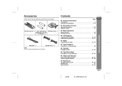
Contents XL-HP500W " General Information Page Precautions 3 Controls and indicators 4 - 6 ENGLISH " Preparation for Use System connections 7 - 10 Remote control 11 " Basic Operation Sound control 12 Setting the ..., 24 " Advanced Features Timer and sleep operation 25 - 27 Enhancing your system 27, 28 " References Troubleshooting chart 29, 30 Maintenance 31 Specifications 31, 32 E-2 02/8/6 XL-HP500W(A)1.fm Accessories Please confirm that the following accessories are included. Remote control 1 "AA" size battery AM loop aerial 1 (UM/SUM-3, R6, HP7 or similar...
Contents XL-HP500W " General Information Page Precautions 3 Controls and indicators 4 - 6 ENGLISH " Preparation for Use System connections 7 - 10 Remote control 11 " Basic Operation Sound control 12 Setting the ..., 24 " Advanced Features Timer and sleep operation 25 - 27 Enhancing your system 27, 28 " References Troubleshooting chart 29, 30 Maintenance 31 Specifications 31, 32 E-2 02/8/6 XL-HP500W(A)1.fm Accessories Please confirm that the following accessories are included. Remote control 1 "AA" size battery AM loop aerial 1 (UM/SUM-3, R6, HP7 or similar...
Operation Manual
Page 4
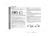
... ! If a CD is at moderate levels. " Care of the disc, particularly the non-label side from your CD collection and player. ! XL-HP500W Precautions ENGLISH " General ! Do not expose the unit to moisture, to high volume levels. Please ensure that which is specified is advisable to... should not be used must be placed on a firm, level surface free from the wall socket, as this surface. ! SHARP will not be drawn to full at switch on speaker efficiency, location, and various other type of the equipment. 10 cm (4") 10 cm (4") 10 cm (4") General Information 10 cm...
... ! If a CD is at moderate levels. " Care of the disc, particularly the non-label side from your CD collection and player. ! XL-HP500W Precautions ENGLISH " General ! Do not expose the unit to moisture, to high volume levels. Please ensure that which is specified is advisable to... should not be used must be placed on a firm, level surface free from the wall socket, as this surface. ! SHARP will not be drawn to full at switch on speaker efficiency, location, and various other type of the equipment. 10 cm (4") 10 cm (4") 10 cm (4") General Information 10 cm...
Operation Manual
Page 6
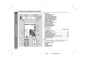
... AC Voltage Selector 9 2. AC Power Lead 7, 9 5. Tape Reverse Play Indicator 5. FM 75 Ohms Aerial Terminal 7, 8 6. Tweeter 2. Speaker Terminals 7, 8 Note: This product is equipped with a cooling fan inside, which begins to run at a specified volume level for better heat ...Indicator " Rear panel Reference page 1. Span Selector Switch 10 10. Timer Recording Indicator 11. " Speaker system 1. Tape Reverse Mode Indicator 4. Speaker Terminals 02/8/6 XL-HP500W(A)1.fm CD Pause Indicator 13. Bass Reflex Duct 4. FM Stereo Receiving Indicator 8. Tape Forward Play...
... AC Voltage Selector 9 2. AC Power Lead 7, 9 5. Tape Reverse Play Indicator 5. FM 75 Ohms Aerial Terminal 7, 8 6. Tweeter 2. Speaker Terminals 7, 8 Note: This product is equipped with a cooling fan inside, which begins to run at a specified volume level for better heat ...Indicator " Rear panel Reference page 1. Span Selector Switch 10 10. Timer Recording Indicator 11. " Speaker system 1. Tape Reverse Mode Indicator 4. Speaker Terminals 02/8/6 XL-HP500W(A)1.fm CD Pause Indicator 13. Bass Reflex Duct 4. FM Stereo Receiving Indicator 8. Tape Forward Play...
Operation Manual
Page 8
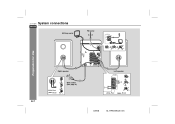
XL-HP500W System connections ENGLISH AM loop aerial FM aerial Preparation for Use Right speaker Left speaker E-7 Red Black Wall socket (See page 9.) Red Black 02/8/6 XL-HP500W(A)1.fm
XL-HP500W System connections ENGLISH AM loop aerial FM aerial Preparation for Use Right speaker Left speaker E-7 Red Black Wall socket (See page 9.) Red Black 02/8/6 XL-HP500W(A)1.fm
Operation Manual
Page 9
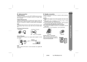
...LOOP socket. Consult your dealer. Incorrect E-8 02/8/6 XL-HP500W(A)1.fm External FM aerial 75 ohm coaxial cable Incorrect Speaker grilles are removable: Make sure nothing comes into or to a stand or a wall with the speaker diaphragms when you face the unit. Aerial connection Supplied... and the left channels. ENGLISH Caution: " Connect the speaker wires to the speakers first, then to the wall > XL-HP500W ! " Do not let the bare speaker wires touch each other. ! Note: Placing the aerial on the speakers. Place the aerial away from the unit for optimum reception...
...LOOP socket. Consult your dealer. Incorrect E-8 02/8/6 XL-HP500W(A)1.fm External FM aerial 75 ohm coaxial cable Incorrect Speaker grilles are removable: Make sure nothing comes into or to a stand or a wall with the speaker diaphragms when you face the unit. Aerial connection Supplied... and the left channels. ENGLISH Caution: " Connect the speaker wires to the speakers first, then to the wall > XL-HP500W ! " Do not let the bare speaker wires touch each other. ! Note: Placing the aerial on the speakers. Place the aerial away from the unit for optimum reception...
Operation Manual
Page 22
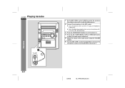
... the MIC LEVEL control towards MAX to increase the microphone volume and towards MIN to the MIC socket. ! XL-HP500W Playing karaoke ENGLISH 1 Set the MIC LEVEL control to MIN to protect the speakers from shock noise and to avoid disturbing noises. 2 Connect the microphone to decrease it . 5 Adjust the volume of...
... the MIC LEVEL control towards MAX to increase the microphone volume and towards MIN to the MIC socket. ! XL-HP500W Playing karaoke ENGLISH 1 Set the MIC LEVEL control to MIN to protect the speakers from shock noise and to avoid disturbing noises. 2 Connect the microphone to decrease it . 5 Adjust the volume of...


