Operation Manual
Page 5
... the included cables and AC cord to insure compliance with part 15 of mercury. Declaration of Conformity SHARP LCD Color Monitor LL-T19D1-H/LL-T19D1-B This device complies with FCC regulation for Users in accordance with the limits for help. Operation is subject to this equipment not expressly approved by one or more of the FCC Rules. However, there is connected. - This...
... the included cables and AC cord to insure compliance with part 15 of mercury. Declaration of Conformity SHARP LCD Color Monitor LL-T19D1-H/LL-T19D1-B This device complies with FCC regulation for Users in accordance with the limits for help. Operation is subject to this equipment not expressly approved by one or more of the FCC Rules. However, there is connected. - This...
Operation Manual
Page 7
...source 12 Turning the power on 12 Changing between input terminals 13 Turning the power off 13 Adjusting the screen display 14 Adjusting the backlight 14 Setting display mode 15 Adjusting the screen display (When using an analog signal 16 Automatic screen adjustment 16 Manual screen adjustment 17 Adjusting the screen display (When using a digital signal 20 Monitor care and repair 22 Monitor care 22 Storage 22 Troubleshooting 22 Specifications 23 Installing set-up information and the ICC profile (For Windows 26 Information about the ColorSync profile (For MacOS 29 Instructions...
...source 12 Turning the power on 12 Changing between input terminals 13 Turning the power off 13 Adjusting the screen display 14 Adjusting the backlight 14 Setting display mode 15 Adjusting the screen display (When using an analog signal 16 Automatic screen adjustment 16 Manual screen adjustment 17 Adjusting the screen display (When using a digital signal 20 Monitor care and repair 22 Monitor care 22 Storage 22 Troubleshooting 22 Specifications 23 Installing set-up information and the ICC profile (For Windows 26 Information about the ColorSync profile (For MacOS 29 Instructions...
Operation Manual
Page 8
.... (model name: NL-C01E) - Microsoft and Windows are permanently lit. Macintosh is to emit high quality video signals. - You are included in unsafe places. Please check that no need to distinguish between programs, the term "Windows" will be transported. - Do not leave the screen displaying idly for errors made with the monitor. - The TFT color LCD panel used . - Also, do not add extension cords. Use only the power cord supplied with...
.... (model name: NL-C01E) - Microsoft and Windows are permanently lit. Macintosh is to emit high quality video signals. - You are included in unsafe places. Please check that no need to distinguish between programs, the term "Windows" will be transported. - Do not leave the screen displaying idly for errors made with the monitor. - The TFT color LCD panel used . - Also, do not add extension cords. Use only the power cord supplied with...
Operation Manual
Page 9
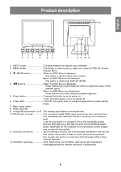
... the monitor and result in power-saving mode. 7. Press the button again to set DISPLAY MODE. 4. Product description English Español Italiano Français Deutsch English 1. buttons When the OSD Menu is necessary for connection. (p.8) It can be transported. Depending on . The separately-sold cable (NL-C01E) is displayed: These buttons are used to turn the power off. 6. INPUT button To switch between the signal's input terminals. 2. The analog signal cable is lit green when in use and...
... the monitor and result in power-saving mode. 7. Press the button again to set DISPLAY MODE. 4. Product description English Español Italiano Français Deutsch English 1. buttons When the OSD Menu is necessary for connection. (p.8) It can be transported. Depending on . The separately-sold cable (NL-C01E) is displayed: These buttons are used to turn the power off. 6. INPUT button To switch between the signal's input terminals. 2. The analog signal cable is lit green when in use and...
Operation Manual
Page 11
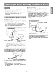
... the signal cable vertically into the connector, and then tighten the screws at both sides. If connecting to the Sun Ultra series, a conversion adapter (commercially available) may be connected, the display may not work correctly.) Analog connection Connect the analog signal cable to the analog RGB output terminal of the computer. - Connecting the monitor to a computer Digital connection Connect the separately-sold digital signal cable (NL-C01E) to either side. DVI-D input terminal Analog RGB input terminal 1 and 2 You can connect to the digital RGB...
... the signal cable vertically into the connector, and then tighten the screws at both sides. If connecting to the Sun Ultra series, a conversion adapter (commercially available) may be connected, the display may not work correctly.) Analog connection Connect the analog signal cable to the analog RGB output terminal of the computer. - Connecting the monitor to a computer Digital connection Connect the separately-sold digital signal cable (NL-C01E) to either side. DVI-D input terminal Analog RGB input terminal 1 and 2 You can connect to the digital RGB...
Operation Manual
Page 12
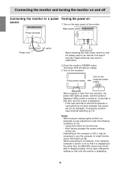
..., the screen will light up information (p.26). - ON When a signal is input from the computer, the power LED lights up green, and the screen is displayed. (After power is set -up orange. 3.Turn on the computer power supply. After having changed the system settings during use the computer to use . - Connecting the monitor and turning the monitor on and off , always wait for the first time. - Press power button. Depending on and off Connecting the monitor to...
..., the screen will light up information (p.26). - ON When a signal is input from the computer, the power LED lights up green, and the screen is displayed. (After power is set -up orange. 3.Turn on the computer power supply. After having changed the system settings during use the computer to use . - Connecting the monitor and turning the monitor on and off , always wait for the first time. - Press power button. Depending on and off Connecting the monitor to...
Operation Manual
Page 14
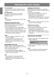
... the button simultaneously. Remove the adjustment lock before attempting to reset values when the adjustment lock is displayed, the control buttons are disabled. Continue to press the buttons until [ADJUSTMENT LOCKED] appears on the monitor power. 2. Without the OSD Menu being displayed, press the or the button. When [RESET] appears on the screen. It is complete. 2. Press the MENU button and the / MODE button simultaneously, and while doing this press the power button (i.e. Continue to press the buttons until [ADJUSTMENT UNLOCKED...
... the button simultaneously. Remove the adjustment lock before attempting to reset values when the adjustment lock is displayed, the control buttons are disabled. Continue to press the buttons until [ADJUSTMENT LOCKED] appears on the monitor power. 2. Without the OSD Menu being displayed, press the or the button. When [RESET] appears on the screen. It is complete. 2. Press the MENU button and the / MODE button simultaneously, and while doing this press the power button (i.e. Continue to press the buttons until [ADJUSTMENT UNLOCKED...
Operation Manual
Page 16
Note: - If your computer's display mode is set to 65K colors, you may see the different color levels in the ADJUSTMENT Menu can be possible.) - In such a case, try displaying an image that makes the entire screen very bright.) - When setting up this monitor for Windows 95/98/2000/Me/XP, and assumes that makes the entire screen light. If using Windows 3.1, open [File Manager] and choose "D drive". 3.Double click on the...
Note: - If your computer's display mode is set to 65K colors, you may see the different color levels in the ADJUSTMENT Menu can be possible.) - In such a case, try displaying an image that makes the entire screen very bright.) - When setting up this monitor for Windows 95/98/2000/Me/XP, and assumes that makes the entire screen light. If using Windows 3.1, open [File Manager] and choose "D drive". 3.Double click on the...
Operation Manual
Page 17
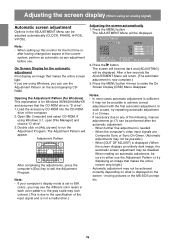
... adjust the screen by using Windows, open the Adjustment Pattern on the accompanying Utility Disk. (p.16) If your system is not Windows, you are manually adjusted. Adjustments to adjust so that horizontal flicker noise is not emitted. ( buttons) At this point relevant menu options can be made using On Screen Display (OSD) Menu provided. How to select [AUTO]. - AUTO: Every menu option is selected. (ADJUSTMENT → GAIN CONTROL → WHITE BALANCE→ MODE SELECT → OSD Menu disappears) Note: - Vertical flicker...
... adjust the screen by using Windows, open the Adjustment Pattern on the accompanying Utility Disk. (p.16) If your system is not Windows, you are manually adjusted. Adjustments to adjust so that horizontal flicker noise is not emitted. ( buttons) At this point relevant menu options can be made using On Screen Display (OSD) Menu provided. How to select [AUTO]. - AUTO: Every menu option is selected. (ADJUSTMENT → GAIN CONTROL → WHITE BALANCE→ MODE SELECT → OSD Menu disappears) Note: - Vertical flicker...
Operation Manual
Page 18
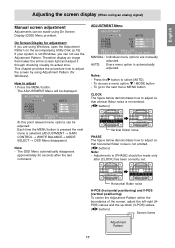
...adjusted using an analog signal) GAIN CONTROL Menu WHITE BALANCE Menu MANUAL: Individual menu options are not using the Auto Gain Control function, set to select [AUTO]. - To display all gradations appear. ( buttons) 18 Selecting [USER] will display the setting values for blue BLACK LEVEL Total screen brightness can be adjusted while watching the color pattern. ( buttons) Color pattern CONTRAST While watching the color pattern, adjustments can be used. If [OUT OF ADJUST] is set to have black area and white area of the image displayed. Use the / MODE button...
...adjusted using an analog signal) GAIN CONTROL Menu WHITE BALANCE Menu MANUAL: Individual menu options are not using the Auto Gain Control function, set to select [AUTO]. - To display all gradations appear. ( buttons) 18 Selecting [USER] will display the setting values for blue BLACK LEVEL Total screen brightness can be adjusted while watching the color pattern. ( buttons) Color pattern CONTRAST While watching the color pattern, adjustments can be used. If [OUT OF ADJUST] is set to have black area and white area of the image displayed. Use the / MODE button...
Operation Manual
Page 19
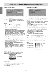
... display may change . - As the resolution input for other than 1280 x 1024 pixels, the display is no need to the left and right. ( buttons) OSD V-POSITION (OSD vertical position) The position of the OSD Menu can be adjusted. ( buttons) Note: - Depending on the screen. 2. To complete adjustment: MENU button OSD H-POSITION (OSD horizontal position) The position of the OSD Menu can specify the horizontal resolution of the image can be moved up and down. ( buttons) SCALING (Level of scaling) The sharpness of a 400line screen when using an analog signal) MODE...
... display may change . - As the resolution input for other than 1280 x 1024 pixels, the display is no need to the left and right. ( buttons) OSD V-POSITION (OSD vertical position) The position of the OSD Menu can be adjusted. ( buttons) Note: - Depending on the screen. 2. To complete adjustment: MENU button OSD H-POSITION (OSD horizontal position) The position of the OSD Menu can specify the horizontal resolution of the image can be moved up and down. ( buttons) SCALING (Level of scaling) The sharpness of a 400line screen when using an analog signal) MODE...
Operation Manual
Page 20
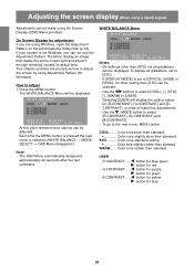
... using On Screen Display (OSD) Menu provided. Color tone redder than standard STD .......... Therefore display an image that makes the entire screen light and adjust it through checking visually its actual tone. button for blue-green button for red button for purple button for green button for yellow button for adjustment If you can not use the Adjustment Pattern. WHITE BALANCE Menu On Screen Display for blue 20 Adjusting the screen display (When using a digital signal) Adjustments can be adjusted. The WHITE BALANCE Menu will display the setting values for Windows). Color...
... using On Screen Display (OSD) Menu provided. Color tone redder than standard STD .......... Therefore display an image that makes the entire screen light and adjust it through checking visually its actual tone. button for blue-green button for red button for purple button for green button for yellow button for adjustment If you can not use the Adjustment Pattern. WHITE BALANCE Menu On Screen Display for blue 20 Adjusting the screen display (When using a digital signal) Adjustments can be adjusted. The WHITE BALANCE Menu will display the setting values for Windows). Color...
Operation Manual
Page 21
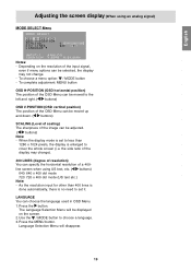
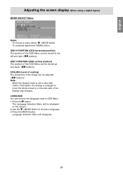
... complete adjustment: MENU button OSD H-POSITION (OSD horizontal position) The position of the OSD Menu can be moved to the left and right. ( buttons) OSD V-POSITION (OSD vertical position) The position of the OSD Menu can be moved up and down. ( buttons) SCALING (Level of scaling) The sharpness of the display may change). Press the button. Use the / MODE button to cover the whole screen (i.e. English Español Italiano Français Deutsch English Adjusting the screen display (When using a digital signal) MODE SELECT Menu Notes: - To choose a menu option: / MODE button - Language...
... complete adjustment: MENU button OSD H-POSITION (OSD horizontal position) The position of the OSD Menu can be moved to the left and right. ( buttons) OSD V-POSITION (OSD vertical position) The position of the OSD Menu can be moved up and down. ( buttons) SCALING (Level of scaling) The sharpness of the display may change). Press the button. Use the / MODE button to cover the whole screen (i.e. English Español Italiano Français Deutsch English Adjusting the screen display (When using a digital signal) MODE SELECT Menu Notes: - To choose a menu option: / MODE button - Language...
Operation Manual
Page 22
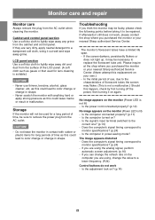
... as this replacement on the monitor (Power LED is not lit) - Is the power cord connected properly? (p.12) No image appears on your nearest Sharp authorized Service Center. Does the computer's signal timing correspond to a lower frequency. (P.24) Control buttons do not work , please contact the shop where you purchased the monitor or your own.) - If you can change in malfunction. If they are using , change in power-saving mode? Never scratch...
... as this replacement on the monitor (Power LED is not lit) - Is the power cord connected properly? (p.12) No image appears on your nearest Sharp authorized Service Center. Does the computer's signal timing correspond to a lower frequency. (P.24) Control buttons do not work , please contact the shop where you purchased the monitor or your own.) - If you can change in malfunction. If they are using , change in power-saving mode? Never scratch...
Operation Manual
Page 24
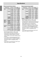
...'s instruction manual to set the timing so that it is receiving timing signals that are not compatible, [OUT OF TIMING] will appear. If the monitor is not receiving any signal (synch signal), [NO SIGNAL] will appear. All are reference values. To connect, another adapter (commercially available) may be connected, the display may not work correctly.) - US text - Specifications Relevant signal timings (analog) Display mode VESA Hsync Vsync Dot frequency Relevant signal timings (digital) Display mode VESA...
...'s instruction manual to set the timing so that it is receiving timing signals that are not compatible, [OUT OF TIMING] will appear. If the monitor is not receiving any signal (synch signal), [NO SIGNAL] will appear. All are reference values. To connect, another adapter (commercially available) may be connected, the display may not work correctly.) - US text - Specifications Relevant signal timings (analog) Display mode VESA Hsync Vsync Dot frequency Relevant signal timings (digital) Display mode VESA...
Operation Manual
Page 25
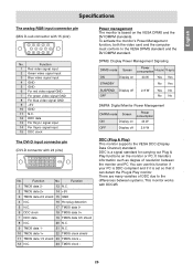
...çais Deutsch English Specifications The analog RGB input connector pin (Mini D-sub connector with DDC2B. 25 Function 1 Red video signal input 2 Green video signal input 3 Blue video signal input 4 GND 5 GND 6 For red video signal GND 7 For green video signal GND 8 For blue video signal GND 9 +5V 10 GND 11 N.C. 12 DDC data 13 For Hsync signal input 14 For Vsync signal input 15 DDC clock The DVI-D input connector pin (DVI-D connector with 24 pins) No. DPMS: Display Power Management Signaling Power DPMS mode Screen consumption H-sync V-sync ON Display on 43 W Yes...
...çais Deutsch English Specifications The analog RGB input connector pin (Mini D-sub connector with DDC2B. 25 Function 1 Red video signal input 2 Green video signal input 3 Blue video signal input 4 GND 5 GND 6 For red video signal GND 7 For green video signal GND 8 For blue video signal GND 9 +5V 10 GND 11 N.C. 12 DDC data 13 For Hsync signal input 14 For Vsync signal input 15 DDC clock The DVI-D input connector pin (DVI-D connector with 24 pins) No. DPMS: Display Power Management Signaling Power DPMS mode Screen consumption H-sync V-sync ON Display on 43 W Yes...
Operation Manual
Page 26
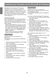
... [Start] button. Click [Next]. 3. Click on [Display]. 4. For Windows 95 Installing monitor set-up information (described below to [STD]. Check that [Copy manufacturer's files from :] is "D drive". 1. Double click on [Settings], [Advanced] and [Monitor]. 5. Click [OK], and close the window. By using the ICC profile, set [DISPLAY MODE] and [WHITE BALANCE] to install the monitor set -up information into Windows 95. Double click on [Settings], [Advanced Properties], and [Monitor], then [Change]. 5. Click on [Display...
... [Start] button. Click [Next]. 3. Click on [Display]. 4. For Windows 95 Installing monitor set-up information (described below to [STD]. Check that [Copy manufacturer's files from :] is "D drive". 1. Double click on [Settings], [Advanced] and [Monitor]. 5. Click [OK], and close the window. By using the ICC profile, set [DISPLAY MODE] and [WHITE BALANCE] to install the monitor set -up information into Windows 95. Double click on [Settings], [Advanced Properties], and [Monitor], then [Change]. 5. Click on [Display...
Operation Manual
Page 27
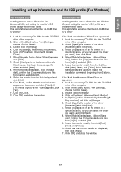
... [OK]. 5. From [Settings], choose [Control Panel]. 3. Click on [Properties], [Driver] and [Update Driver]. 6. Click [OK], and close the window. When [Models] is displayed, click on [Have disk], confirm that the monitor's name appears on [Have disk], confirm that the CD-ROM drive is "D drive". If the "Add new Hardware Wizard" has appeared: 1. Check [Display a list of all the drivers in a specific location, so you...
... [OK]. 5. From [Settings], choose [Control Panel]. 3. Click on [Properties], [Driver] and [Update Driver]. 6. Click [OK], and close the window. When [Models] is displayed, click on [Have disk], confirm that the monitor's name appears on [Have disk], confirm that the CD-ROM drive is "D drive". If the "Add new Hardware Wizard" has appeared: 1. Check [Display a list of all the drivers in a specific location, so you...
Operation Manual
Page 28
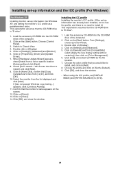
...], and close the window. Click on [Add]. 8. Click on [Close]. 14. Click on [Color Management]. 6. From [Settings], choose [Control Panel]. 3. When [Hardware Update Wizard] appears, check [Install from [Compatibility] select [Apply the new display setting without restarting], then click on [General] and from a list or specific location [Advanced]] and click [Next]. 8. Click on [Properties], [Driver] and [Update Driver]. 7. Click on the [Start] button. Load the accessory CD...
...], and close the window. Click on [Add]. 8. Click on [Close]. 14. Click on [Color Management]. 6. From [Settings], choose [Control Panel]. 3. When [Hardware Update Wizard] appears, check [Install from [Compatibility] select [Apply the new display setting without restarting], then click on [General] and from a list or specific location [Advanced]] and click [Next]. 8. Click on [Properties], [Driver] and [Update Driver]. 7. Click on the [Start] button. Load the accessory CD...
Operation Manual
Page 29
.... When using the ColorSync profile, set [DISPLAY MODE] and [WHITE BALANCE] to the ColorSync profile folder in your system. - Depending on the control panel, choose the profile to be realized when used with MacOS 8.5 or above. - Please follow the computer's own operation manual while reading this. 1.Load the accessory CD-ROM into the CD-ROM drive of the LCD monitor. A ColorSync...
.... When using the ColorSync profile, set [DISPLAY MODE] and [WHITE BALANCE] to the ColorSync profile folder in your system. - Depending on the control panel, choose the profile to be realized when used with MacOS 8.5 or above. - Please follow the computer's own operation manual while reading this. 1.Load the accessory CD-ROM into the CD-ROM drive of the LCD monitor. A ColorSync...


