Service Manual
Page 1
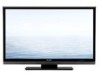
... 3. S08S2LCC4655U LCD COLOR TELEVISION MODEL LC-C4655U In the interests of the set. This Service Manual covers the modifications alone. SPECIFICATIONS [1] SPECIFICATIONS 1-1 CHAPTER 2. This document has been published to the LC-42D65U (No. PRINTED WIRING BOARD ASSEMBLIES [1] R/C, LED Unit 7-1 CHAPTER 8. REMOVING OF MAJOR PARTS [1] REMOVING OF MAJOR PARTS 4-1 CHAPTER 5. SCHEMATIC DIAGRAM [1] DESCRIPTION OF SCHEMATIC DIAGRAM .........8-1 [2] R/C, LED...
... 3. S08S2LCC4655U LCD COLOR TELEVISION MODEL LC-C4655U In the interests of the set. This Service Manual covers the modifications alone. SPECIFICATIONS [1] SPECIFICATIONS 1-1 CHAPTER 2. This document has been published to the LC-42D65U (No. PRINTED WIRING BOARD ASSEMBLIES [1] R/C, LED Unit 7-1 CHAPTER 8. REMOVING OF MAJOR PARTS [1] REMOVING OF MAJOR PARTS 4-1 CHAPTER 5. SCHEMATIC DIAGRAM [1] DESCRIPTION OF SCHEMATIC DIAGRAM .........8-1 [2] R/C, LED...
Service Manual
Page 3
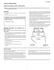
...other metal parts in this manual; LSCA-CF46E55TUY PRECAUTION Service Manual LC-C4655U IMPORTANT SERVICE SAFETY PRECAUTION Service work should be identical to those used only for leakage current in LCD color television have these checks.) Any reading of a substitute replacement parts which..., no modification of any circuit should be performed only by " " and shaded areas in the Replacement Parts List and Schematic Diagrams. ii Inspect all lead dress to all safety checks and the servicing guidelines which have special safety-related characteristics. The...
...other metal parts in this manual; LSCA-CF46E55TUY PRECAUTION Service Manual LC-C4655U IMPORTANT SERVICE SAFETY PRECAUTION Service work should be identical to those used only for leakage current in LCD color television have these checks.) Any reading of a substitute replacement parts which..., no modification of any circuit should be performed only by " " and shaded areas in the Replacement Parts List and Schematic Diagrams. ii Inspect all lead dress to all safety checks and the servicing guidelines which have special safety-related characteristics. The...
Service Manual
Page 39
... test points are 50V, unless otherwise noted. BE SURE TO REPLACE THESE PARTS WITH SPECIFIED ONES FOR MAIN- SCHEMATIC DIAGRAM [1] DESCRIPTION OF SCHEMATIC DIAGRAM 1. CAPACITOR 1) All capacitors are µF, unless otherwise noted. (P=pF=µµF). 2) All capacitors ... AS POTENTIAL SHOCK HAZARDS WHEN THE CHASSIS IS OPERATING. AVIS DE SECURITE IMPORTANT: LES PIECES MARQUEES " " ( ) SONT IMPOR- Service Manual 8 - 1 LC-C4655U CAUTION: This circuit diagram is omitted. (K=kΩ=1000Ω, M=MΩ). 2) All resistors are ± 5%, unless otherwise noted. (K= ± 10%, F=...
... test points are 50V, unless otherwise noted. BE SURE TO REPLACE THESE PARTS WITH SPECIFIED ONES FOR MAIN- SCHEMATIC DIAGRAM [1] DESCRIPTION OF SCHEMATIC DIAGRAM 1. CAPACITOR 1) All capacitors are µF, unless otherwise noted. (P=pF=µµF). 2) All capacitors ... AS POTENTIAL SHOCK HAZARDS WHEN THE CHASSIS IS OPERATING. AVIS DE SECURITE IMPORTANT: LES PIECES MARQUEES " " ( ) SONT IMPOR- Service Manual 8 - 1 LC-C4655U CAUTION: This circuit diagram is omitted. (K=kΩ=1000Ω, M=MΩ). 2) All resistors are ± 5%, unless otherwise noted. (K= ± 10%, F=...