Service Manual
Page 1
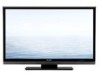
... are important for maintaining the safety and performance of the set . S08S2LCC4655U LCD COLOR TELEVISION MODEL LC-C4655U In the interests of the set . OVERALL WIRING DIAGRAM [1] OVERALL WIRING DIAGRAM 6-1 CHAPTER 7. Be sure to those specified should be used . TopPage LC-C4655U SERVICE MANUAL No. REMOVING OF MAJOR PARTS [1] REMOVING OF MAJOR PARTS 4-1 CHAPTER 5. CONTENTS OUTLINE AND...
... are important for maintaining the safety and performance of the set . S08S2LCC4655U LCD COLOR TELEVISION MODEL LC-C4655U In the interests of the set . OVERALL WIRING DIAGRAM [1] OVERALL WIRING DIAGRAM 6-1 CHAPTER 7. Be sure to those specified should be used . TopPage LC-C4655U SERVICE MANUAL No. REMOVING OF MAJOR PARTS [1] REMOVING OF MAJOR PARTS 4-1 CHAPTER 5. CONTENTS OUTLINE AND...
Service Manual
Page 2
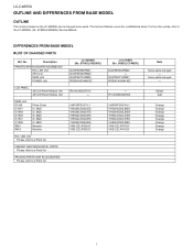
...PARTS Please refer to a Parts list PACKING PARTS AND ACCESSORIES Please refer to the LC-42D65U (No. Delete Add Change Change Change Change Change Change Change Change i S78N2LC42D65U) Service Manual. S78N2LC42D65U) DUNTKE868FM01 DUNTKE266FM02 DUNTKE716FM02 RDENCA298WJQZ LCD PANEL 42"LCD Panel Module Unit 46"LCD...Unit KEY Unit MAIN Unit POWER Unit LC-42D65U (No. Some parts changed - For the other points, refer to a Parts list LC-C4655U (No. No. LC-C4655U LOCU-C4T6L55IUNE AND DIFFERENCES FROM BASE MSOerDvEicLe Manual OUTLINE This model is based on the LC-42D65U and is changed some parts.
...PARTS Please refer to a Parts list PACKING PARTS AND ACCESSORIES Please refer to the LC-42D65U (No. Delete Add Change Change Change Change Change Change Change Change i S78N2LC42D65U) Service Manual. S78N2LC42D65U) DUNTKE868FM01 DUNTKE266FM02 DUNTKE716FM02 RDENCA298WJQZ LCD PANEL 42"LCD Panel Module Unit 46"LCD...Unit KEY Unit MAIN Unit POWER Unit LC-42D65U (No. Some parts changed - For the other points, refer to a Parts list LC-C4655U (No. No. LC-C4655U LOCU-C4T6L55IUNE AND DIFFERENCES FROM BASE MSOerDvEicLe Manual OUTLINE This model is based on the LC-42D65U and is changed some parts.
Service Manual
Page 3
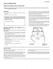
...Service Manual LC-C4655U IMPORTANT SERVICE SAFETY PRECAUTION Service work should be attempted. 2. Disconnect AC power before returning the monitor to the owner. C A U T I O N : F O R C O N T I N U E D PROTECTION AGAINST A RISK OF FIRE REPLACE ONLY WITH SAME TYPE FUSE. The use of any circuit should be performed only by qualified service...protective devices such as the factory recommended replacement parts shown in this service manual, may create shock, fire or other metal parts in LCD color television have the same safety characteristics as non-metallic control knobs, insulation ...
...Service Manual LC-C4655U IMPORTANT SERVICE SAFETY PRECAUTION Service work should be attempted. 2. Disconnect AC power before returning the monitor to the owner. C A U T I O N : F O R C O N T I N U E D PROTECTION AGAINST A RISK OF FIRE REPLACE ONLY WITH SAME TYPE FUSE. The use of any circuit should be performed only by qualified service...protective devices such as the factory recommended replacement parts shown in this service manual, may create shock, fire or other metal parts in LCD color television have the same safety characteristics as non-metallic control knobs, insulation ...
Service Manual
Page 5
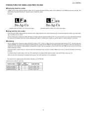
...If a different type of time. As the melting point of the soldering bit may cause damage or accident due to turn on the PWBs and service manuals. Make sure to cracks. Lead-free wire solder for extended period of solder stays on the PWB silk. Lead-free solder contains more tin, and... bit is attached on and off or the maximum heat-resistance temperature of this model employs lead-free solder. PRECAUTIONS FOR USING LEAD-FREE SOLDER LC-C4655U „Employing lead-free solder • "PWBs" of parts may be exceeded, remove the bit from the PWB as soon as you are not...
...If a different type of time. As the melting point of the soldering bit may cause damage or accident due to turn on the PWBs and service manuals. Make sure to cracks. Lead-free wire solder for extended period of solder stays on the PWB silk. Lead-free solder contains more tin, and... bit is attached on and off or the maximum heat-resistance temperature of this model employs lead-free solder. PRECAUTIONS FOR USING LEAD-FREE SOLDER LC-C4655U „Employing lead-free solder • "PWBs" of parts may be exceeded, remove the bit from the PWB as soon as you are not...
Service Manual
Page 7
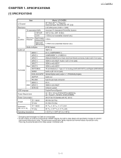
LCC-HC4A655PUTER 1. There may be some deviations from these values in with HDCP SERVICE Software update OSD language English/French/Spanish Power Requirement AC 120 V, 60 Hz (FOR NORTH AMERICA) AC 110-...messages via Cable are nominal values of continuous improvement, SHARP reserves the right to make design and specification changes for product improvement without prior notice. The performance specification figures indicated are unreceivable. SPECIFICATIONS [1] SPECIFICATIONS Service Manual LC-C4655U LCD panel Item Model: LC-C4655U 46" Class (45 63/64" Diagonal) Advanced ...
LCC-HC4A655PUTER 1. There may be some deviations from these values in with HDCP SERVICE Software update OSD language English/French/Spanish Power Requirement AC 120 V, 60 Hz (FOR NORTH AMERICA) AC 110-...messages via Cable are nominal values of continuous improvement, SHARP reserves the right to make design and specification changes for product improvement without prior notice. The performance specification figures indicated are unreceivable. SPECIFICATIONS [1] SPECIFICATIONS Service Manual LC-C4655U LCD panel Item Model: LC-C4655U 46" Class (45 63/64" Diagonal) Advanced ...
Service Manual
Page 8
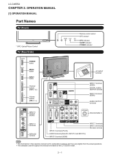
LC-C4655U LCC-HC4A655PUTER 2. The examples used throughout this operation manual are based on the LC-C5255U model. 2 - 1 OPERATION MANUAL [1] OPERATION MANUAL Part Names TV (Front) * OPC: Optical Picture Control TV (Rear/Side) Service Manual Remote control sensor OPC sensor* OPC indicator SLEEP indicator POWER indicator POWER button MENU button INPUT button Channel buttons (CH / ) Volume buttons (VOL / ) AC...
LC-C4655U LCC-HC4A655PUTER 2. The examples used throughout this operation manual are based on the LC-C5255U model. 2 - 1 OPERATION MANUAL [1] OPERATION MANUAL Part Names TV (Front) * OPC: Optical Picture Control TV (Rear/Side) Service Manual Remote control sensor OPC sensor* OPC indicator SLEEP indicator POWER indicator POWER button MENU button INPUT button Channel buttons (CH / ) Volume buttons (VOL / ) AC...
Service Manual
Page 10
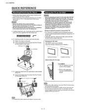
...This TV should be performed by qualified service personnel. Customers should only be mounted on a.... 2 Set the post for details. SHARP bears no responsibility for improper mounting or mounting...the TV You can ask a qualified service professional about using the optional mount bracket.... hex key supplied with the AN-52AG4 (SHARP) wall mount bracket. This will prevent it ... 2 Soft cushion 1 1 0/5/10/15/20° LC-C4655U The "b" position is at the 4 locations on the rear...rear of the base. Refer to the post. LC-C4655U QUICK REFERENCE Attaching/Detaching the Stand Before attaching ...
...This TV should be performed by qualified service personnel. Customers should only be mounted on a.... 2 Set the post for details. SHARP bears no responsibility for improper mounting or mounting...the TV You can ask a qualified service professional about using the optional mount bracket.... hex key supplied with the AN-52AG4 (SHARP) wall mount bracket. This will prevent it ... 2 Soft cushion 1 1 0/5/10/15/20° LC-C4655U The "b" position is at the 4 locations on the rear...rear of the base. Refer to the post. LC-C4655U QUICK REFERENCE Attaching/Detaching the Stand Before attaching ...
Service Manual
Page 20
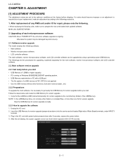
... • The file system of the USB Memory. Software version upgrade The model employs the following procedure. 1. Unplug the AC cord. 2. LC-C4655U LCC-HC4A655PUTER 5. After replacement of Main Board terminals, under INPUT3 terminal. 3. The followings are set to prepare the new units loaded with updated ... When replacing the following units, make an adjustment according to get ready the USB Memory for version upgrade. ADJUSTMENT Service Manual [1] ADJUSTMENT PROCEDURE The adjustment values are the procedures for upgrading, explained separately for version upgrade. 1.
... • The file system of the USB Memory. Software version upgrade The model employs the following procedure. 1. Unplug the AC cord. 2. LC-C4655U LCC-HC4A655PUTER 5. After replacement of Main Board terminals, under INPUT3 terminal. 3. The followings are set to prepare the new units loaded with updated ... When replacing the following units, make an adjustment according to get ready the USB Memory for version upgrade. ADJUSTMENT Service Manual [1] ADJUSTMENT PROCEDURE The adjustment values are the procedures for upgrading, explained separately for version upgrade. 1.

Service Manual
Page 37
LCC-HC4A655PUTER 6. OVERALL WIRING DIAGRAM [1] OVERALL WIRING DIAGRAM Service Manual LC-C4655U I H G F E D C B A 1 䇼㪢㪤䇽 㪈 㪌 㪬㪪㪙 㪭㪆㪣㪩 㪟㪛㪤㪠 Analog RGB PC Audio IN 䌈䌄䌍&#...
LCC-HC4A655PUTER 6. OVERALL WIRING DIAGRAM [1] OVERALL WIRING DIAGRAM Service Manual LC-C4655U I H G F E D C B A 1 䇼㪢㪤䇽 㪈 㪌 㪬㪪㪙 㪭㪆㪣㪩 㪟㪛㪤㪠 Analog RGB PC Audio IN 䌈䌄䌍&#...

Service Manual
Page 38
LC-C4655U LCC-HC4A655PUTER 7. PRINTED WIRING BOARD ASSEMBLIES [1] R/C, LED Unit I Service Manual H R/C, LED Unit (Side-A) G F E R/C, LED Unit (Side-A Chip) D 3 C107 R101 C102 RMC101 SLD101 C D101 R132 C105 IC101 C104 R135 R136 D103 R105 R102 R117 R137 R107 R104 R109 Q104 R108 R126 Q102 R121 D114 Q103 R106 R138 R123 D115 R124 Q107 Q105 R110 Q106 R127 R122 C110 R103 C108 C101 RMC102 R120 R119 IC102 R118 R116 P101 D116 C103 C111 R139 R140 P102 B A 1 2 3 4 5 6 7 8 9 10 11 12 13 14 15 16 17 18 19 20 21 22 7 - 1
LC-C4655U LCC-HC4A655PUTER 7. PRINTED WIRING BOARD ASSEMBLIES [1] R/C, LED Unit I Service Manual H R/C, LED Unit (Side-A) G F E R/C, LED Unit (Side-A Chip) D 3 C107 R101 C102 RMC101 SLD101 C D101 R132 C105 IC101 C104 R135 R136 D103 R105 R102 R117 R137 R107 R104 R109 Q104 R108 R126 Q102 R121 D114 Q103 R106 R138 R123 D115 R124 Q107 Q105 R110 Q106 R127 R122 C110 R103 C108 C101 RMC102 R120 R119 IC102 R118 R116 P101 D116 C103 C111 R139 R140 P102 B A 1 2 3 4 5 6 7 8 9 10 11 12 13 14 15 16 17 18 19 20 21 22 7 - 1
Service Manual
Page 39
... REGARDED AS POTENTIAL SHOCK HAZARDS WHEN THE CHASSIS IS OPERATING. SCHEMATIC DIAGRAM [1] DESCRIPTION OF SCHEMATIC DIAGRAM 1. Signals are fed by a color bar signal generator for servicing purpose and the above voltages are 50V, unless otherwise noted. CAUTION: This circuit diagram is omitted. (K=kΩ=1000Ω, M=MΩ). 2) All resistors are ± ...16W, unless otherwise noted. LCC-HC4A655PUTER 8. INDICATION OF RESISTOR & CAPACITOR: RESISTOR 1) The unit of AC 120V. AVIS DE SECURITE IMPORTANT: LES PIECES MARQUEES " " ( ) SONT IMPOR- Service Manual 8 - 1 LC-C4655U
... REGARDED AS POTENTIAL SHOCK HAZARDS WHEN THE CHASSIS IS OPERATING. SCHEMATIC DIAGRAM [1] DESCRIPTION OF SCHEMATIC DIAGRAM 1. Signals are fed by a color bar signal generator for servicing purpose and the above voltages are 50V, unless otherwise noted. CAUTION: This circuit diagram is omitted. (K=kΩ=1000Ω, M=MΩ). 2) All resistors are ± ...16W, unless otherwise noted. LCC-HC4A655PUTER 8. INDICATION OF RESISTOR & CAPACITOR: RESISTOR 1) The unit of AC 120V. AVIS DE SECURITE IMPORTANT: LES PIECES MARQUEES " " ( ) SONT IMPOR- Service Manual 8 - 1 LC-C4655U


