Service Manual
Page 7
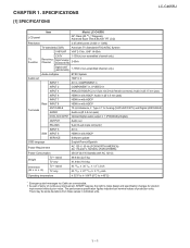
LCC-HC4A655PUTER 1. The performance specification figures indicated are nominal values of continuous improvement, SHARP reserves the right to make design and specification changes for Analog (VHF/UHF/CATV) and Digital (AIR/CABLE) Audio in (Ø 3.5 mm jack)... (W H D) TV + stand TV only 43 53/64 43 53/64 30 3/64 27 47/64 13 1/2 inch 3 29/32 inch Operating temperature 32°F to 104°F (0°C to 40°C) *1 Emergency alert messages via Cable are unreceivable. SPECIFICATIONS [1] SPECIFICATIONS Service Manual LC-C4655U LCD panel Item Model: LC-C4655U 46" Class (45...
LCC-HC4A655PUTER 1. The performance specification figures indicated are nominal values of continuous improvement, SHARP reserves the right to make design and specification changes for Analog (VHF/UHF/CATV) and Digital (AIR/CABLE) Audio in (Ø 3.5 mm jack)... (W H D) TV + stand TV only 43 53/64 43 53/64 30 3/64 27 47/64 13 1/2 inch 3 29/32 inch Operating temperature 32°F to 104°F (0°C to 40°C) *1 Emergency alert messages via Cable are unreceivable. SPECIFICATIONS [1] SPECIFICATIONS Service Manual LC-C4655U LCD panel Item Model: LC-C4655U 46" Class (45...
Service Manual
Page 10
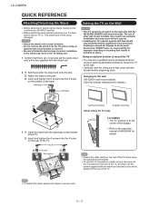
... the rear of the TV, and then use of the TV. Hex key 2 Screws 2 Soft cushion 1 1 0/5/10/15/20° LC-C4655U The "b" position is at the 4 locations on the wall only with the bracket before beginning work. Detach the cable clamp on the rear of...a wall, remove the covers at the center of the base. LC-C4655U QUICK REFERENCE Attaching/Detaching the Stand Before attaching (or detaching) the stand, unplug the AC cord from being damaged. Attach the base to follow the instructions. SHARP bears no responsibility for details.) 2 Vertical mounting Angular mounting About ...
... the rear of the TV, and then use of the TV. Hex key 2 Screws 2 Soft cushion 1 1 0/5/10/15/20° LC-C4655U The "b" position is at the 4 locations on the wall only with the bracket before beginning work. Detach the cable clamp on the rear of...a wall, remove the covers at the center of the base. LC-C4655U QUICK REFERENCE Attaching/Detaching the Stand Before attaching (or detaching) the stand, unplug the AC cord from being damaged. Attach the base to follow the instructions. SHARP bears no responsibility for details.) 2 Vertical mounting Angular mounting About ...
Service Manual
Page 14
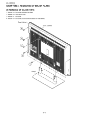
Rear Cabinet 4 Front Cabinet 4 2 3 1 Stand 4 - 1 Remove the 4 VESA Hole Covers. 3. Remove the 4 lock screws, 9 lock screws and detach the Rear Cabinet. Remove the 1 lock screw. 4. REMOVING OF MAJOR PARSTeSrvice Manual [1] REMOVING OF MAJOR PARTS 1. Remove the 4 lock screws and detach the Stand. 2. LC-C4655U LCC-HC4A655PUTER 4.
Rear Cabinet 4 Front Cabinet 4 2 3 1 Stand 4 - 1 Remove the 4 VESA Hole Covers. 3. Remove the 4 lock screws, 9 lock screws and detach the Rear Cabinet. Remove the 1 lock screw. 4. REMOVING OF MAJOR PARSTeSrvice Manual [1] REMOVING OF MAJOR PARTS 1. Remove the 4 lock screws and detach the Stand. 2. LC-C4655U LCC-HC4A655PUTER 4.
Service Manual
Page 30
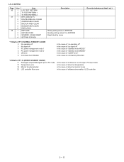
LC-C4655U Page 36 37 38 Line 1 2 3 1 2 3 4 5 6 1 2 3 4 Item LCD TEST PATTERN TV TEST PATTERN 1 TV TEST PATTERN 2 KEY LOCK(1217) KOUTEI AREA ALL CLEAR A MODE AREA CLEAR ... AREA CLEAR EXECUTION EEP SAVE EEP RECOVER STANDBY CAUSE RESET SETTING FOR ADJ Description Writing setting values to EEPROM Reading setting values from EEPROM Reset stand by cause Remarks (adjustment detail, etc.) *1 Details of P1.9 (NORMAL STANDBY CAUSE) 2 No operation off 3 No signal off 4 PC power management mode 1 5 PC power management...
LC-C4655U Page 36 37 38 Line 1 2 3 1 2 3 4 5 6 1 2 3 4 Item LCD TEST PATTERN TV TEST PATTERN 1 TV TEST PATTERN 2 KEY LOCK(1217) KOUTEI AREA ALL CLEAR A MODE AREA CLEAR ... AREA CLEAR EXECUTION EEP SAVE EEP RECOVER STANDBY CAUSE RESET SETTING FOR ADJ Description Writing setting values to EEPROM Reading setting values from EEPROM Reset stand by cause Remarks (adjustment detail, etc.) *1 Details of P1.9 (NORMAL STANDBY CAUSE) 2 No operation off 3 No signal off 4 PC power management mode 1 5 PC power management...

Service Manual
Page 47
... Unit (LP) J Connecting Cord (4pin L=1000mm) MAIN Unit to SPEAKER (SP) J Connecting Cord (5-9pin L=1500mm) POWER to INVERTER Unit (LB) LC-C4655U 7 NO. Polyethylene Bag (for Screw) - - No. Wrapping Paper - - Polyethylene Bag - - Stand Case - - N - Polyethylene Bag - - Packing Case (Bottom) - Packing Add. - - PARTS CODE PRICE NEW PART RANK MARK DELIVERY DESCRIPTION [7] PACKING PARTS (NOT...
... Unit (LP) J Connecting Cord (4pin L=1000mm) MAIN Unit to SPEAKER (SP) J Connecting Cord (5-9pin L=1500mm) POWER to INVERTER Unit (LB) LC-C4655U 7 NO. Polyethylene Bag (for Screw) - - No. Wrapping Paper - - Polyethylene Bag - - Stand Case - - N - Polyethylene Bag - - Packing Case (Bottom) - Packing Add. - - PARTS CODE PRICE NEW PART RANK MARK DELIVERY DESCRIPTION [7] PACKING PARTS (NOT...


