Service Manual
Page 1
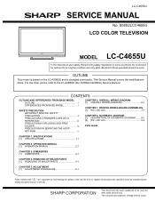
... with " " are subject to change without notice. TopPage LC-C4655U SERVICE MANUAL No. S08S2LCC4655U LCD COLOR TELEVISION MODEL LC-C4655U In the interests of user-safety (Required by safety regulations in some parts. OUTLINE This model is based on the LC-42D65U and is changed some countries) the set should be used for after sales service only...
... with " " are subject to change without notice. TopPage LC-C4655U SERVICE MANUAL No. S08S2LCC4655U LCD COLOR TELEVISION MODEL LC-C4655U In the interests of user-safety (Required by safety regulations in some parts. OUTLINE This model is based on the LC-42D65U and is changed some countries) the set should be used for after sales service only...
Service Manual
Page 9
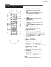
... by pressing A, B, C and D. Part Names Remote Control Unit 1 2 3 4 5 6 7 8 9 10 LC-C4655U 1 POWER: Switch the TV power on the screen. 20 10 EXIT: Turn off the menu screen. 11 DISPLAY: Display the channel information. 12 SLEEP: Set the sleep timer. 13 AV MODE: Select an audio or video...INPUT 4, 5, 6 or 7: STANDARD, MOVIE, GAME, PC, xvYCC (INPUT 4/5/6 only) USER, DYNAMIC (Fixed), DYNAMIC) 14 MUTE: Mute the sound. 15 VOL / : Set the volume. 16 CH / : Select the channel. 17 ENT: Jumps to a channel after selecting with the 0-9 buttons. 18 INPUT: Select a TV input source. (TV, ...
... by pressing A, B, C and D. Part Names Remote Control Unit 1 2 3 4 5 6 7 8 9 10 LC-C4655U 1 POWER: Switch the TV power on the screen. 20 10 EXIT: Turn off the menu screen. 11 DISPLAY: Display the channel information. 12 SLEEP: Set the sleep timer. 13 AV MODE: Select an audio or video...INPUT 4, 5, 6 or 7: STANDARD, MOVIE, GAME, PC, xvYCC (INPUT 4/5/6 only) USER, DYNAMIC (Fixed), DYNAMIC) 14 MUTE: Mute the sound. 15 VOL / : Set the volume. 16 CH / : Select the channel. 17 ENT: Jumps to a channel after selecting with the 0-9 buttons. 18 INPUT: Select a TV input source. (TV, ...
Service Manual
Page 10
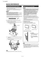
Do not remove the stand from the TV unless using an optional wall mount bracket to the wall. Hex key 3 Screws Setting the TV on the Wall CAUTION This TV should be performed by qualified service personnel. Carefully read the instructions that results in the ... the center of the TV. Be sure to the post. Incorrect installation of the stand may cause serious injuries. SHARP bears no responsibility for the stand unit onto the box. LC-C4655U QUICK REFERENCE Attaching/Detaching the Stand Before attaching (or detaching) the stand, unplug the AC cord from being damaged....
Do not remove the stand from the TV unless using an optional wall mount bracket to the wall. Hex key 3 Screws Setting the TV on the Wall CAUTION This TV should be performed by qualified service personnel. Carefully read the instructions that results in the ... the center of the TV. Be sure to the post. Incorrect installation of the stand may cause serious injuries. SHARP bears no responsibility for the stand unit onto the box. LC-C4655U QUICK REFERENCE Attaching/Detaching the Stand Before attaching (or detaching) the stand, unplug the AC cord from being damaged....
Service Manual
Page 11
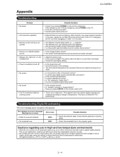
...sound. Has the power been turned on the TV. In this may leave trails or appear slightly delayed. Check the input signal setting. Is the sleep timer set? Is correct input signal source selected after 1 or 2 minutes. Is "Variable" selected in a hot or cold location. ...that is suddenly turned off /with sidebar screen. room, office), the picture may cause the cabinet to deform and the Liquid Crystal panel to malfunction. LC-C4655U Appendix Troubleshooting Problem No power Unit cannot be operated. External influences such as picture size made correctly? Are batteries worn out?...
...sound. Has the power been turned on the TV. In this may leave trails or appear slightly delayed. Check the input signal setting. Is the sleep timer set? Is correct input signal source selected after 1 or 2 minutes. Is "Variable" selected in a hot or cold location. ...that is suddenly turned off /with sidebar screen. room, office), the picture may cause the cabinet to deform and the Liquid Crystal panel to malfunction. LC-C4655U Appendix Troubleshooting Problem No power Unit cannot be operated. External influences such as picture size made correctly? Are batteries worn out?...
Service Manual
Page 12
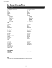
...LC-C4655U On-Screen Display Menu Menu Items For TV/INPUT 1/2/3 Mode Picture Menu OPC Backlight Contrast Brightness Color Tint Sharpness Advanced C.M.S.-Hue C.M.S.-Saturation Color Temp. Program Title Display Favorite CH Game Play Time Operation Lock Out For HDMI/PC-IN Mode Picture Menu OPC Backlight Contrast Brightness Color Tint Sharpness...Some menu items may not be displayed depending on the selected input source. 2 - 5 Active Contrast I /P Setting Film Mode Digital Noise Reduction Monochrome Range of OPC Reset Audio Menu Treble Bass Balance Surround Bass Enhancer Reset Power Control...
...LC-C4655U On-Screen Display Menu Menu Items For TV/INPUT 1/2/3 Mode Picture Menu OPC Backlight Contrast Brightness Color Tint Sharpness Advanced C.M.S.-Hue C.M.S.-Saturation Color Temp. Program Title Display Favorite CH Game Play Time Operation Lock Out For HDMI/PC-IN Mode Picture Menu OPC Backlight Contrast Brightness Color Tint Sharpness...Some menu items may not be displayed depending on the selected input source. 2 - 5 Active Contrast I /P Setting Film Mode Digital Noise Reduction Monochrome Range of OPC Reset Audio Menu Treble Bass Balance Surround Bass Enhancer Reset Power Control...
Service Manual
Page 20
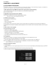
.... Plug in the AC cord with power button pressed down after 5 seconds, unpress the power button. 4. The followings are set to the root directory (folder) of each microprocessor software CAUTION: Never "POWER OFF" the unit when software upgrade is necessary to...seconds. Copy the file LAKEAxxx.USB (named temporarily) for the main software, monitor microprocessor software, and LCD controller software. 2.2. LC-C4655U LCC-HC4A655PUTER 5. ADJUSTMENT Service Manual [1] ADJUSTMENT PROCEDURE The adjustment values are the procedures for upgrading, explained separately for version upgrade ...
.... Plug in the AC cord with power button pressed down after 5 seconds, unpress the power button. 4. The followings are set to the root directory (folder) of each microprocessor software CAUTION: Never "POWER OFF" the unit when software upgrade is necessary to...seconds. Copy the file LAKEAxxx.USB (named temporarily) for the main software, monitor microprocessor software, and LCD controller software. 2.2. LC-C4655U LCC-HC4A655PUTER 5. ADJUSTMENT Service Manual [1] ADJUSTMENT PROCEDURE The adjustment values are the procedures for upgrading, explained separately for version upgrade ...

Service Manual
Page 21
... upgrade. 8. Even a single failure in the process will trigger the upgrade failure screen. Upon completion of a failure, repeat the upgrade process. UPGRADE FAILURE SDB655 LC-C4655U NOTE: In the event of the whole process, the upgrade success screen as shown below appears. You can check the new software version on this...If the process repeatedly fails, it is likely that the hardware need fixing. 6. NOTE: When you are done with the software version upgrade, start the set, go to the top page of the adjustment process screen and check the main software version information. 5 - 2
... upgrade. 8. Even a single failure in the process will trigger the upgrade failure screen. Upon completion of a failure, repeat the upgrade process. UPGRADE FAILURE SDB655 LC-C4655U NOTE: In the event of the whole process, the upgrade success screen as shown below appears. You can check the new software version on this...If the process repeatedly fails, it is likely that the hardware need fixing. 6. NOTE: When you are done with the software version upgrade, start the set, go to the top page of the adjustment process screen and check the main software version information. 5 - 2

Service Manual
Page 22
... an upgrade screen will be shown if upgrade screen was shown at 5. The power led will be automatically retried up to start the set, go to upgrade the software 1. UPGRADE SUCCESS SDB655 8. Monitor microprocessor software version upgrade Create the USB memory for version upgrade (prepared...SDB655 NOTE: In the event of the adjustment process screen and check the mon- Also, the upgrade failure screen will blink continuously. LC-C4655U 2.3. Unplug the AC cord and remove the USB Memory for monitor microprocessor software version upgrade to the USB memory. 2.3.1 How to...
... an upgrade screen will be shown if upgrade screen was shown at 5. The power led will be automatically retried up to start the set, go to upgrade the software 1. UPGRADE SUCCESS SDB655 8. Monitor microprocessor software version upgrade Create the USB memory for version upgrade (prepared...SDB655 NOTE: In the event of the adjustment process screen and check the mon- Also, the upgrade failure screen will blink continuously. LC-C4655U 2.3. Unplug the AC cord and remove the USB Memory for monitor microprocessor software version upgrade to the USB memory. 2.3.1 How to...

Service Manual
Page 24
If the settings are tampered in this case, wait 10 seconds or so before plugging.) CAUTION: Use due care in the adjustment process mode. In this mode, unrecoverable system damage may result. 4. LC-C4655U 3. The letter "" appears on the screen. 3) Next, hold down the "VOL (-)" ...CH ( / ) VOL (+/-) Function Moving an item (line) by one (UP/DOWN) Changing a selected item setting (+1/ -1) Turing a page (PREVIOUS/NEXT) Changing a selected line setting (+10/ -10) Input switching (toggle switching) Executing a function *Input mode is switched automatically when relevant adjustment is...
If the settings are tampered in this case, wait 10 seconds or so before plugging.) CAUTION: Use due care in the adjustment process mode. In this mode, unrecoverable system damage may result. 4. LC-C4655U 3. The letter "" appears on the screen. 3) Next, hold down the "VOL (-)" ...CH ( / ) VOL (+/-) Function Moving an item (line) by one (UP/DOWN) Changing a selected item setting (+1/ -1) Turing a page (PREVIOUS/NEXT) Changing a selected line setting (+10/ -10) Input switching (toggle switching) Executing a function *Input mode is switched automatically when relevant adjustment is...

Service Manual
Page 25
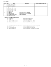
... main operation time Reset Accumulated monitor operation time Reset Reset LAMP ERROR X-coordinate setting for VIC READ Y-coordinate setting for VIC READ Collected color data setting for VIC READ Signal type setting for VIC READ Picture level acquisition function CVBS and TUNER signal level adjustment CVBS...and VCHIP test (10ch) Tuning test and VCHIP test (15ch) Component 15K picture level adjustment (main) Component 33K picture level adjustment (main) LC-C4655U Remarks (adjustment detail, etc.) Refer to *1 under the list for details Refer to *2 under the list for details Level appears in the...
... main operation time Reset Accumulated monitor operation time Reset Reset LAMP ERROR X-coordinate setting for VIC READ Y-coordinate setting for VIC READ Collected color data setting for VIC READ Signal type setting for VIC READ Picture level acquisition function CVBS and TUNER signal level adjustment CVBS...and VCHIP test (10ch) Tuning test and VCHIP test (15ch) Component 15K picture level adjustment (main) Component 33K picture level adjustment (main) LC-C4655U Remarks (adjustment detail, etc.) Refer to *1 under the list for details Refer to *2 under the list for details Level appears in the...
Service Manual
Page 26
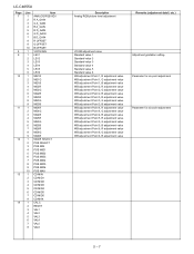
LC-C4655U Page 7 8 9 10 11 12 13 14 Line 1 2 3 4 5 6 7 8 9 10 1 1 2 3 4 5 6 1 2 3 4 5 6 7 8 9 1 2 3 4 5 6 7 8 9 1 2 3 4 5 6 7 8 9 10 1 2 3 4 5 6 7 8 1 2 3 4 5 6 7 8 Item ANALOG RGB ADJ R A_GAIN G A_GAIN B A_GAIN R D_GAIN G D_GAIN B D_GAIN R OFFSET G OFFSET B OFFSET VCOM ADJ LEV1 ... Point 5, G adjustment value WB adjustment Point 5, B adjustment value WB adjustment Point 6, R adjustment value WB adjustment Point 6, G adjustment value WB adjustment Point 6, B adjustment value Adjustment gradation setting. Parameter for six-point adjustment Parameter for six-point adjustment 5 - 7
LC-C4655U Page 7 8 9 10 11 12 13 14 Line 1 2 3 4 5 6 7 8 9 10 1 1 2 3 4 5 6 1 2 3 4 5 6 7 8 9 1 2 3 4 5 6 7 8 9 1 2 3 4 5 6 7 8 9 10 1 2 3 4 5 6 7 8 1 2 3 4 5 6 7 8 Item ANALOG RGB ADJ R A_GAIN G A_GAIN B A_GAIN R D_GAIN G D_GAIN B D_GAIN R OFFSET G OFFSET B OFFSET VCOM ADJ LEV1 ... Point 5, G adjustment value WB adjustment Point 5, B adjustment value WB adjustment Point 6, R adjustment value WB adjustment Point 6, G adjustment value WB adjustment Point 6, B adjustment value Adjustment gradation setting. Parameter for six-point adjustment Parameter for six-point adjustment 5 - 7
Service Manual
Page 30
LC-C4655U Page 36 37 38 Line 1 2 3 1 2 3 4 5 6 1 2 3 4 Item LCD TEST PATTERN TV TEST PATTERN 1 TV TEST PATTERN 2 KEY LOCK(1217) KOUTEI AREA ALL CLEAR A MODE AREA CLEAR BACKUP AREA CLEAR B MODE AREA CLEAR EXECUTION EEP SAVE EEP RECOVER STANDBY CAUSE RESET SETTING FOR ADJ Description Writing setting values to EEPROM Reading setting values from EEPROM Reset...
LC-C4655U Page 36 37 38 Line 1 2 3 1 2 3 4 5 6 1 2 3 4 Item LCD TEST PATTERN TV TEST PATTERN 1 TV TEST PATTERN 2 KEY LOCK(1217) KOUTEI AREA ALL CLEAR A MODE AREA CLEAR BACKUP AREA CLEAR B MODE AREA CLEAR EXECUTION EEP SAVE EEP RECOVER STANDBY CAUSE RESET SETTING FOR ADJ Description Writing setting values to EEPROM Reading setting values from EEPROM Reset...

Service Manual
Page 31
... in finding a problem when you repair the troubled set. * EEP SAVE (Page 38/38) Storage of EEP adjustment value * EEP RECOVER (Page 38/38) Retrieval of US-10ch) to white level) 7.2. Feed the RF signal (by use of EEP adjustment value from storage area LC-C4655U 7. Special features * STANDBY CAUSE (Page 1/38) Display...
... in finding a problem when you repair the troubled set. * EEP SAVE (Page 38/38) Storage of EEP adjustment value * EEP RECOVER (Page 38/38) Retrieval of US-10ch) to white level) 7.2. Feed the RF signal (by use of EEP adjustment value from storage area LC-C4655U 7. Special features * STANDBY CAUSE (Page 1/38) Display...
Service Manual
Page 33
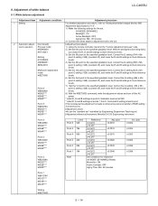
.... 60 minutes Ins. Correct the G setting (580 x 6thpoint G setting / 928) (rounded off ), and make the R and B settings to the specified gradation level. Correct the G setting (284 x 6th- point G setting / 928) (rounded off ), and make the R and B settings to their reference levels. 7) Set the 1st point to their reference levels. White balance adjustment LC-C4655U Adjustment item Adjustment conditions Adjustment...
.... 60 minutes Ins. Correct the G setting (580 x 6thpoint G setting / 928) (rounded off ), and make the R and B settings to the specified gradation level. Correct the G setting (284 x 6th- point G setting / 928) (rounded off ), and make the R and B settings to their reference levels. 7) Set the 1st point to their reference levels. White balance adjustment LC-C4655U Adjustment item Adjustment conditions Adjustment...

Service Manual
Page 34
... it again. Make the following settings are initialized in page 2/38. Send each adjustment command. 9. Bring the cursor on screen, it is displayed on the keyboard. 7. To exit the adjustment process mode, unplug the AC power cable from the RS232C operation mode to enter the command. 8. LC-C4655U 8.2. Adjusting procedure by typing in...
... it again. Make the following settings are initialized in page 2/38. Send each adjustment command. 9. Bring the cursor on screen, it is displayed on the keyboard. 7. To exit the adjustment process mode, unplug the AC power cable from the RS232C operation mode to enter the command. 8. LC-C4655U 8.2. Adjusting procedure by typing in...
Service Manual
Page 39
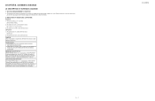
.... AVIS DE SECURITE IMPORTANT: LES PIECES MARQUEES " " ( ) SONT IMPOR- Service Manual 8 - 1 LC-C4655U BE SURE TO REPLACE THESE PARTS WITH SPECIFIED ONES FOR MAIN- INDICATION OF RESISTOR & CAPACITOR: RESISTOR 1) The unit of AC 120V. TAINING THE SAFETY AND PERFORMANCE OF THE SET. CAPACITOR 1) All capacitors are µF, unless otherwise noted. (P=pF=µµ...
.... AVIS DE SECURITE IMPORTANT: LES PIECES MARQUEES " " ( ) SONT IMPOR- Service Manual 8 - 1 LC-C4655U BE SURE TO REPLACE THESE PARTS WITH SPECIFIED ONES FOR MAIN- INDICATION OF RESISTOR & CAPACITOR: RESISTOR 1) The unit of AC 120V. TAINING THE SAFETY AND PERFORMANCE OF THE SET. CAPACITOR 1) All capacitors are µF, unless otherwise noted. (P=pF=µµ...
Service Manual
Page 41
... these parts with " " are important for maintaining the safety of the set . This document has been published to change without notice. The contents are arranged in alphabetical order. PartsGuide LC-C4655U PARTS GUIDE No. S08S2LCC4655U Note: The reference numbers on the PWB are ...subject to be used for maintaining the safety and performance of the set . MODEL CONTENTS LC-C4655U [1] PRINTED WIRING BOARD ASSEMBLIES [2] LCD PANEL (NOTE: THE PARTS HERE SHOWN ARE SUPPLIED AS AN ASSEMBLY BUT NOT INDEPENDENTLY.) [3]...
... these parts with " " are important for maintaining the safety of the set . This document has been published to change without notice. The contents are arranged in alphabetical order. PartsGuide LC-C4655U PARTS GUIDE No. S08S2LCC4655U Note: The reference numbers on the PWB are ...subject to be used for maintaining the safety and performance of the set . MODEL CONTENTS LC-C4655U [1] PRINTED WIRING BOARD ASSEMBLIES [2] LCD PANEL (NOTE: THE PARTS HERE SHOWN ARE SUPPLIED AS AN ASSEMBLY BUT NOT INDEPENDENTLY.) [3]...


