Programmer Manual
Page 2
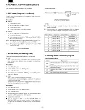
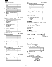
... the RECEIPT FEED and JOURNAL FEED keys can be set Free key Free key setup 0 *1 complete. keys and direct PLU keys) SRV memory File allocation report This reset returns all memory and keyboard contents. Procedure 1) Turn off the AC switch. 2) Set the MODE switch to its initial settings. reset (Program Loop Reset... other than that key position. SERVICE (SRV) MODE The SRV key is disabled. 2: Push the key on keys other than dept. SRV. Master reset (All memory clear) There are two possible methods to perform a master reset. • MRS-1 Used to clear all...
... the RECEIPT FEED and JOURNAL FEED keys can be set Free key Free key setup 0 *1 complete. keys and direct PLU keys) SRV memory File allocation report This reset returns all memory and keyboard contents. Procedure 1) Turn off the AC switch. 2) Set the MODE switch to its initial settings. reset (Program Loop Reset... other than that key position. SERVICE (SRV) MODE The SRV key is disabled. 2: Push the key on keys other than dept. SRV. Master reset (All memory clear) There are two possible methods to perform a master reset. • MRS-1 Used to clear all...
Programmer Manual
Page 6
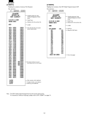
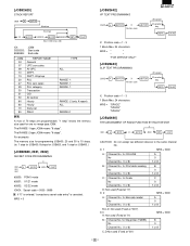
.../ No.of used records [JOB#990] Reading the Contents of used records Error message File memory start address Empty memory start address Memory end address Note: The SRV mode programming printout lists the actual memory files. Step No./SSP data File table No./No.of records/ No.of blocks/No.of.../AT Header graphical logo (Default:Graphical LOGO only) Date/Time Machine No./Consective No. JOB# SSP No. [JOB#970] Reading the contents of memory File Allocation Key operation 970 → @/FOR → CA/AT Header graphical logo (Default:Graphical LOGO only) Date/Time Machine No./Consective No.
.../ No.of used records [JOB#990] Reading the Contents of used records Error message File memory start address Empty memory start address Memory end address Note: The SRV mode programming printout lists the actual memory files. Step No./SSP data File table No./No.of records/ No.of blocks/No.of.../AT Header graphical logo (Default:Graphical LOGO only) Date/Time Machine No./Consective No. JOB# SSP No. [JOB#970] Reading the contents of memory File Allocation Key operation 970 → @/FOR → CA/AT Header graphical logo (Default:Graphical LOGO only) Date/Time Machine No./Consective No.
Programmer Manual
Page 15
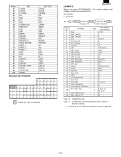
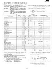
... 6,12,21 (or 23),31,37 24 25 Type = 0 ; Text(12) Dept. Create/Erase only Type = 1 ; SERVICE FINAL DEPOSIT DEPOSIT RFND SCALE OPEN TARE INHIBIT ER-A450T KEY POSITION KEY TEXT CONV3 CONV4 FSTEND RA RA2 PO PO2 CASH# BIRTH UPC AMT DEPT# REPEAT INQ NO DEL PRCHNG P1 P2 P3 SLIP... 46 52 58 64 01 05 09 13 17 21 25 29 34 39 45 51 57 63 :FIXED KEY (NO TO CHANGE) [JOB#971] Memory file group PROGRAMMING. (File creation deletion and change of group No. BIRTHDAY UPC AMT DEPT# REPEAT INQUIRE NO DELETE PRICE CHANGE PRICE 1 PRICE 2 PRICE 3 SLIP...
... 6,12,21 (or 23),31,37 24 25 Type = 0 ; Text(12) Dept. Create/Erase only Type = 1 ; SERVICE FINAL DEPOSIT DEPOSIT RFND SCALE OPEN TARE INHIBIT ER-A450T KEY POSITION KEY TEXT CONV3 CONV4 FSTEND RA RA2 PO PO2 CASH# BIRTH UPC AMT DEPT# REPEAT INQ NO DEL PRCHNG P1 P2 P3 SLIP... 46 52 58 64 01 05 09 13 17 21 25 29 34 39 45 51 57 63 :FIXED KEY (NO TO CHANGE) [JOB#971] Memory file group PROGRAMMING. (File creation deletion and change of group No. BIRTHDAY UPC AMT DEPT# REPEAT INQUIRE NO DELETE PRICE CHANGE PRICE 1 PRICE 2 PRICE 3 SLIP...
Programmer Manual
Page 38
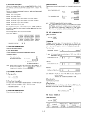
... SBTL CA/AT X: Table No. = 1 - 9 YYYY: Weight = 0 - 99.99 ( Enter without decimal point.) MRS = 0 [JOB#2619] HOURLY REPORT (Starting time) 0 2619 @/FOR abb CA/AT a: Memory type 30 minutes (24 hour) 60 minutes (24 hour) bb: Starting time (hour): ex) Case 1. A 0 1 00 - 23 2619 @/FOR 007 CA/AT X1 Hourly report...
... SBTL CA/AT X: Table No. = 1 - 9 YYYY: Weight = 0 - 99.99 ( Enter without decimal point.) MRS = 0 [JOB#2619] HOURLY REPORT (Starting time) 0 2619 @/FOR abb CA/AT a: Memory type 30 minutes (24 hour) 60 minutes (24 hour) bb: Starting time (hour): ex) Case 1. A 0 1 00 - 23 2619 @/FOR 007 CA/AT X1 Hourly report...
Programmer Manual
Page 39
"1 step" means the memory size used (Fixed at "00") for Print data sending No Channel No. (1 or 8) B 0 1 or 8 C: Channel No. for Barcode reader No Channel No. (1 or 8) A 0 1 or 8 B,C,D: Not ... ABCD SBTL CA/AT CAUTION: Do not assign two different devices to the same channel No. The RANGE-1 type JOB# means "8 steps". For example) The memory size for programming JOB#00, 20 and 50 is canceled. DEPT.
"1 step" means the memory size used (Fixed at "00") for Print data sending No Channel No. (1 or 8) B 0 1 or 8 C: Channel No. for Barcode reader No Channel No. (1 or 8) A 0 1 or 8 B,C,D: Not ... ABCD SBTL CA/AT CAUTION: Do not assign two different devices to the same channel No. The RANGE-1 type JOB# means "8 steps". For example) The memory size for programming JOB#00, 20 and 50 is canceled. DEPT.
Programmer Manual
Page 47
... MET SALES (Frash-read : These reports are taken by the supervisor or manager in the third digit of all reports can be entered. For Z reports, Memory is stopped, the consecutive number or Z counter doesn't return to the following operation. To stop the printing reports: The printing of a job code, periodic reports...
... MET SALES (Frash-read : These reports are taken by the supervisor or manager in the third digit of all reports can be entered. For Z reports, Memory is stopped, the consecutive number or Z counter doesn't return to the following operation. To stop the printing reports: The printing of a job code, periodic reports...

Service Manual
Page 8
...Loop Reset) Used to return the machine back to default keyboard layout. Master reset (All memory clear) There are two possible methods to perform a master reset. • MRS-1 Used to clear all memory contents and return machine back to its initial settings and return keyboard back to its operational... and JOURNAL FEED keys can be set *2 Free key 0 *1 Disable Free key setup complete. SERVICE RESET AND MASTER RESET 1. This reset returns all memory and keyboard contents. Method 2 will not reset the CKDC8. Procedure 1) Unplug the AC cord from the wall outlet. 2) Set the MODE switch to ...
...Loop Reset) Used to return the machine back to default keyboard layout. Master reset (All memory clear) There are two possible methods to perform a master reset. • MRS-1 Used to clear all memory contents and return machine back to its initial settings and return keyboard back to its operational... and JOURNAL FEED keys can be set *2 Free key 0 *1 Disable Free key setup complete. SERVICE RESET AND MASTER RESET 1. This reset returns all memory and keyboard contents. Method 2 will not reset the CKDC8. Procedure 1) Unplug the AC cord from the wall outlet. 2) Set the MODE switch to ...
Service Manual
Page 12
...P56 72 P57 73 P60 /NEJ NU /NER VSS TRG1 /PSTOP /CKDCR2 OPDS FVPON FMRS /SLIPLMP /STOP /ERS 74 P61 75 P62 76 P63 77 P64 /DRS /CSS /CDS /RR 78 P65 /RSS 79 P66 80...(GND) IN Nu (GND) OUT Nu (GND) IN Nu (GND) OUT Nu (GND) OUT Nu (GND) OUT ER signal for RS232 (Equipment Ready) IN DR signal for RS232 (Data set Ready) IN CS signal for RS232 (Clear to ...(Ready to Receive) (Nu) OUT RS signal for RS232 (Request to CKDC) SHIFT ENABLE (from CKDC) FISCAL MEMORY RESET (Nu) FISCAL MEMORY BUSY (Nu) FISCAL MEMORY READY (Nu) POP-UP DISPLAY SENSOR (Nu) GND DATA BUS 0 DATA BUS 1 DATA BUS 2 DATA BUS...
...P56 72 P57 73 P60 /NEJ NU /NER VSS TRG1 /PSTOP /CKDCR2 OPDS FVPON FMRS /SLIPLMP /STOP /ERS 74 P61 75 P62 76 P63 77 P64 /DRS /CSS /CDS /RR 78 P65 /RSS 79 P66 80...(GND) IN Nu (GND) OUT Nu (GND) IN Nu (GND) OUT Nu (GND) OUT Nu (GND) OUT ER signal for RS232 (Equipment Ready) IN DR signal for RS232 (Data set Ready) IN CS signal for RS232 (Clear to ...(Ready to Receive) (Nu) OUT RS signal for RS232 (Request to CKDC) SHIFT ENABLE (from CKDC) FISCAL MEMORY RESET (Nu) FISCAL MEMORY BUSY (Nu) FISCAL MEMORY READY (Nu) POP-UP DISPLAY SENSOR (Nu) GND DATA BUS 0 DATA BUS 1 DATA BUS 2 DATA BUS...
Service Manual
Page 24
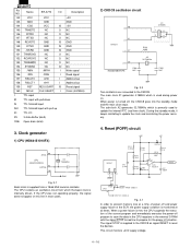
... 143 144 145 146 147 148 149 150 151 152 153 154 155 156 157 158 159 160 I ID IS ISU IO 3S ON6 Name ER-A770 I/O VCC VCC GND GND /CSD VCC IS TRNDTD NC O /DTRD NC O /RTSD NC O RCVDTD GND IS /CTSD GND IS /DSRD GND IS TRNRDYD NC... R116 9.1KG 1SS133 R117 2.7K R118 R119 2.7K 56K 8 3+ B 1 2 - This circuit monitors +24V supply voltage. 4 - 16 During the standby mode, it keeps oscillating to prevent memory loss at a time of the ECR, the power supply condition is turned off and power supply failure of power off , the CKDC8 goes into the...
... 143 144 145 146 147 148 149 150 151 152 153 154 155 156 157 158 159 160 I ID IS ISU IO 3S ON6 Name ER-A770 I/O VCC VCC GND GND /CSD VCC IS TRNDTD NC O /DTRD NC O /RTSD NC O RCVDTD GND IS /CTSD GND IS /DSRD GND IS TRNRDYD NC... R116 9.1KG 1SS133 R117 2.7K R118 R119 2.7K 56K 8 3+ B 1 2 - This circuit monitors +24V supply voltage. 4 - 16 During the standby mode, it keeps oscillating to prevent memory loss at a time of the ECR, the power supply condition is turned off and power supply failure of power off , the CKDC8 goes into the...
Service Manual
Page 25
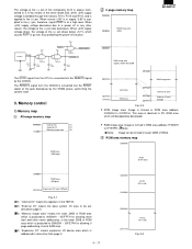
... Image is formed in RAM area address 1F0000H to 1F7E7FH. ( Note) Note: Image can be addressed in page 0. ( 3) "Memory image area" means the lower 32KB of ROM area which is projected to 000000H ~ 007FFFH for allowing reset start and other vector addressing... is applied to a power off situation. The voltage at a high level. Memory control 1) Memory map All range memory map 000000H Internal I/O (*1) External I/O (*2) 1C0000H Memory image area (*3) RAM area (10M byte) 0 page memory map 000000H 004000H ROM image area 32KB 008000H RAM image area slightly smaller than32KB 00F800H...
... Image is formed in RAM area address 1F0000H to 1F7E7FH. ( Note) Note: Image can be addressed in page 0. ( 3) "Memory image area" means the lower 32KB of ROM area which is projected to 000000H ~ 007FFFH for allowing reset start and other vector addressing... is applied to a power off situation. The voltage at a high level. Memory control 1) Memory map All range memory map 000000H Internal I/O (*1) External I/O (*2) 1C0000H Memory image area (*3) RAM area (10M byte) 0 page memory map 000000H 004000H ROM image area 32KB 008000H RAM image area slightly smaller than32KB 00F800H...
Service Manual
Page 26
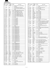
Note used in the ER-A445P. (Not used) Access is performed with two RAM chip select signals, RAS2 and RAS3. The control register in the image area of 0 page. (lower32KB). I/O area memory map 00FF80H (*1) MPCCS 00FFA0H NOT USE 00FFC0H 00FFD0H 00FFE0H 00FFE8H 00FFF0H 00FFFFH MCR1 (NOT USE) MCR2 ... 5-7 IPLON: IPL board detection signal incorporated in the OPC (optionperipheral controller) using the base signal OPTCS for option decoding. RAM area memory map 100000H NOT USE 1C0000H 1E0000H 200000H RAS1 128K Byte RAS2 128K Byte 280000H 400000H RAS3 512K Byte (OPTION) (MAX 2MB) NOT ...
Note used in the ER-A445P. (Not used) Access is performed with two RAM chip select signals, RAS2 and RAS3. The control register in the image area of 0 page. (lower32KB). I/O area memory map 00FF80H (*1) MPCCS 00FFA0H NOT USE 00FFC0H 00FFD0H 00FFE0H 00FFE8H 00FFF0H 00FFFFH MCR1 (NOT USE) MCR2 ... 5-7 IPLON: IPL board detection signal incorporated in the OPC (optionperipheral controller) using the base signal OPTCS for option decoding. RAM area memory map 100000H NOT USE 1C0000H 1E0000H 200000H RAS1 128K Byte RAS2 128K Byte 280000H 400000H RAS3 512K Byte (OPTION) (MAX 2MB) NOT ...
Service Manual
Page 30
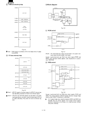
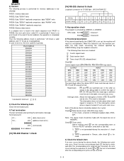
2) Power off sequence When the CPU senses a service interruption, it performs the necessary procedures for the CPU to the CKDC8. Then the CPU outputs a reset request to stop. Reset request SHEN DON'T CARE SCK LDRQ RES1 TL 20µsec or more TH 20µsec or more TL+TH
2) Power off sequence When the CPU senses a service interruption, it performs the necessary procedures for the CPU to the CKDC8. Then the CPU outputs a reset request to stop. Reset request SHEN DON'T CARE SCK LDRQ RES1 TL 20µsec or more TH 20µsec or more TL+TH
Service Manual
Page 35
...the mode switch is set to the CPU A/D convertor is displayed sequentially. 2) Functional description Perform the following address check is performed further. The memory contents should not be checked (1C0000H~1FFFFFH). Termination printout: Normal termination 120 Abnormal termination Ex - - - - - 120 X = 1: ...Note: " " means the ROM version number. If no error occurs through all addresses, the check ends normally. Option RAM Memory to be checked ER-03RA Address area to be checked 200000H ∼ 27FFFFH 5 - 5 PASS5: Read and compare data "AAAAH." Check point ...
...the mode switch is set to the CPU A/D convertor is displayed sequentially. 2) Functional description Perform the following address check is performed further. The memory contents should not be checked (1C0000H~1FFFFFH). Termination printout: Normal termination 120 Abnormal termination Ex - - - - - 120 X = 1: ...Note: " " means the ROM version number. If no error occurs through all addresses, the check ends normally. Option RAM Memory to be checked ER-03RA Address area to be checked 200000H ∼ 27FFFFH 5 - 5 PASS5: Read and compare data "AAAAH." Check point ...
Service Manual
Page 36
... [15] RS-232 Channel 1 check [16] RS-232 channel 8 check Loop back connector for memory addresses to PASS6, the error print (error code E1) is generated in a misoperation. Read check: ER and RS are performed. Check Timer check Before making check , set , the machine will result in... 10msec. shows an invalid address. In case of check . 2) TRQ1 is performed. An error occurs during the above checks should be checked. PASS1: memory data save PASS2: ...
... [15] RS-232 Channel 1 check [16] RS-232 channel 8 check Loop back connector for memory addresses to PASS6, the error print (error code E1) is generated in a misoperation. Read check: ER and RS are performed. Check Timer check Before making check , set , the machine will result in... 10msec. shows an invalid address. In case of check . 2) TRQ1 is performed. An error occurs during the above checks should be checked. PASS1: memory data save PASS2: ...
Service Manual
Page 39
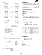
... 0 1 2 3 4 5 6 7 HEX 8 9 A B C D E F ASCII 38 39 41 42 43 44 45 46 Character 8 9 A B C D E F 6. ECR-ER-02FD cable 25PIN D-SUB ER-02FD SD 2 9PIN D-SUB ECR 3 SD RD 3 RTS 4 DCD 8 2 RD 7 RTS 1 DCD DTR 20 4 DTR DSR 6 6 DSR CTS 5 8 CTS SG 7 5 SG FG... 1 FRAME GROUND is connected to the shield of 64 bytes from the address 0000. End massage: Fixed to 30303030. Data format A single byte image of the memory...
... 0 1 2 3 4 5 6 7 HEX 8 9 A B C D E F ASCII 38 39 41 42 43 44 45 46 Character 8 9 A B C D E F 6. ECR-ER-02FD cable 25PIN D-SUB ER-02FD SD 2 9PIN D-SUB ECR 3 SD RD 3 RTS 4 DCD 8 2 RD 7 RTS 1 DCD DTR 20 4 DTR DSR 6 6 DSR CTS 5 8 CTS SG 7 5 SG FG... 1 FRAME GROUND is connected to the shield of 64 bytes from the address 0000. End massage: Fixed to 30303030. Data format A single byte image of the memory...
Service Manual
Page 40
... baud rate setting: ECR to ECR only) 5) Start the sending ECR. Saving/Loading of data to receive data from another ECR or the ER-02FD, the memory size of the ER-02FD are used.) DS-1 DS-2 123456781234 OFF ON OFF ON OFF OFF OFF ON X ON OFF OFF Data rate 4 6 OFF OFF ON... side as follows: 998 @/FOR CA/AT 3) Press the SEND key on the FD unit. 4) Data transmission is started and the Green lamp on the ER-02FD blinks. Saving data 1) Turn on the power switch and insert a floppy disk which stores the data. 2) Start the RECEIVE JOB on the ECR side...
... baud rate setting: ECR to ECR only) 5) Start the sending ECR. Saving/Loading of data to receive data from another ECR or the ER-02FD, the memory size of the ER-02FD are used.) DS-1 DS-2 123456781234 OFF ON OFF ON OFF OFF OFF ON X ON OFF OFF Data rate 4 6 OFF OFF ON... side as follows: 998 @/FOR CA/AT 3) Press the SEND key on the FD unit. 4) Data transmission is started and the Green lamp on the ER-02FD blinks. Saving data 1) Turn on the power switch and insert a floppy disk which stores the data. 2) Start the RECEIVE JOB on the ECR side...
Service Manual
Page 43
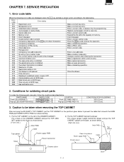
... code Error status Action E01 Registration error Make a correct key entry. Enter a correct code, or declare it by the programming. E07 Memory is enterd. E09 Invalid cashier code is full. E32 No entry of entry. PARTS NAME PARTS CODE LOCATION Front LED (HDSP5621) Front ... SERVICE PRECAUTION 1. E03 Undefined code is inhibited. E33 The current cashier code should not be taken when removing the TOP CABINET After removing the ER-A450T's TOP CABINET, put the TOP CABINET upright on the base, as shown below. [ Front view ] Main PWB Cable 2) Put the TOP...
... code Error status Action E01 Registration error Make a correct key entry. Enter a correct code, or declare it by the programming. E07 Memory is enterd. E09 Invalid cashier code is full. E32 No entry of entry. PARTS NAME PARTS CODE LOCATION Front LED (HDSP5621) Front ... SERVICE PRECAUTION 1. E03 Undefined code is inhibited. E33 The current cashier code should not be taken when removing the TOP CABINET After removing the ER-A450T's TOP CABINET, put the TOP CABINET upright on the base, as shown below. [ Front view ] Main PWB Cable 2) Put the TOP...

Service Manual
Page 48
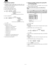
8 7 6 5 MEMORY 2-1D 2-1D 2-8C /RD /WR A[0..18] 2-8D D[0..7] 4-7D 3-8C +5V C177 0.1u D C176 47U/16V IC13 ROM1 A16 A15 A12 A7 A6 A5 A4 A3 ...
8 7 6 5 MEMORY 2-1D 2-1D 2-8C /RD /WR A[0..18] 2-8D D[0..7] 4-7D 3-8C +5V C177 0.1u D C176 47U/16V IC13 ROM1 A16 A15 A12 A7 A6 A5 A4 A3 ...

Service Manual
Page 49
8 7 6 5 4 3 OPTION MEMORY/OPT CN D A[0..18] C B D[0..7] +5V IC16 RAM A18 A16 A14 A12 A7 A6 A5 A4 A3 A2 A1 A0 1 2 3 4 5 6 7 8 9 10 11 12 N.C A16 A14 A12 A7 ...
8 7 6 5 4 3 OPTION MEMORY/OPT CN D A[0..18] C B D[0..7] +5V IC16 RAM A18 A16 A14 A12 A7 A6 A5 A4 A3 A2 A1 A0 1 2 3 4 5 6 7 8 9 10 11 12 N.C A16 A14 A12 A7 ...


