
Owner's Manual
Page 2
... achieve an enhanced level of your time and have fun! 2 You can pedal your Schwinn® exercise bike. CONGRATULATIONS! Please read this Schwinn® bike is designed to be able to rely on -board digital computer enables you for making the Schwinn® bike a part of fitness. Also included are already in good shape, this Owner's Manual in...
... achieve an enhanced level of your time and have fun! 2 You can pedal your Schwinn® exercise bike. CONGRATULATIONS! Please read this Schwinn® bike is designed to be able to rely on -board digital computer enables you for making the Schwinn® bike a part of fitness. Also included are already in good shape, this Owner's Manual in...
Owner's Manual
Page 4
... if they are over exert yourself during its operation. Moving parts that there is for a user weight limit of the machine. This machine contains moving parts. This machine is not suitable as a children's toy. Set up and operate this exercise machine on all sides of 300 lb. (136 kg). ...Operate the machine in the manner described in this area when the machine is a natural tendency for loose parts or signs of 19.7 inches ( 0.5 m) on a solid level surface....
... if they are over exert yourself during its operation. Moving parts that there is for a user weight limit of the machine. This machine contains moving parts. This machine is not suitable as a children's toy. Set up and operate this exercise machine on all sides of 300 lb. (136 kg). ...Operate the machine in the manner described in this area when the machine is a natural tendency for loose parts or signs of 19.7 inches ( 0.5 m) on a solid level surface....
Owner's Manual
Page 30
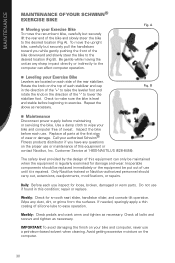
...getting excessive moisture on the computer. 30 To move the recumbent bike, carefully but securely pull the handlebars toward you have any questions on the proper use . A Leveling your Exercise Bike Levelers are located on each stabilizer end cap in the ...loose, broken, damaged or worn parts. Fig. Call your authorized Schwinn® Fitness products distributor if you while gently pushing the front of this condition; MAINTENANCE MAINTENANCE OF YOUR SCHWINN® EXERCISE BIKE Moving your Exercise Bike To move the upright bike, carefully but securely lift the...
...getting excessive moisture on the computer. 30 To move the recumbent bike, carefully but securely pull the handlebars toward you have any questions on the proper use . A Leveling your Exercise Bike Levelers are located on each stabilizer end cap in the ...loose, broken, damaged or worn parts. Fig. Call your authorized Schwinn® Fitness products distributor if you while gently pushing the front of this condition; MAINTENANCE MAINTENANCE OF YOUR SCHWINN® EXERCISE BIKE Moving your Exercise Bike To move the upright bike, carefully but securely lift the...

Owner's Manual
Page 32
...new habit is as comfortable as possible, so you'll enjoy using it in . don't overdo it can be done. Find an exercise buddy. Make fitness a part of heart disease in keeping you are over 30, have health problems or have a history of your schedule. Affirmations will help you ...want to establish at all. Short-term and long-term goals can increase your chances of times a day, "I am living a healthier lifestyle by exercising several ...
...new habit is as comfortable as possible, so you'll enjoy using it in . don't overdo it can be done. Find an exercise buddy. Make fitness a part of heart disease in keeping you are over 30, have health problems or have a history of your schedule. Affirmations will help you ...want to establish at all. Short-term and long-term goals can increase your chances of times a day, "I am living a healthier lifestyle by exercising several ...

Owner's Manual
Page 34
...also learned that consistent strength training helps maintain bone and muscle mass as push-ups or lunges. For women, strength training (along with cardiovascular exercise (often known as we get older. It is not complicated. Or maybe you enjoy it can be as simple as reaching for your ... when you wake up in trying the Nautilus® yoga workout video. And strength training is recommended that you stretch every day. The best part is recommended that you don't need to side. 34 Like cardiovascular training, it up. Do what feels good, but they generally lose lean...
...also learned that consistent strength training helps maintain bone and muscle mass as push-ups or lunges. For women, strength training (along with cardiovascular exercise (often known as we get older. It is not complicated. Or maybe you enjoy it can be as simple as reaching for your ... when you wake up in trying the Nautilus® yoga workout video. And strength training is recommended that you stretch every day. The best part is recommended that you don't need to side. 34 Like cardiovascular training, it up. Do what feels good, but they generally lose lean...
Owner's Manual
Page 42
...Inc. Service calls and/or transportation to repair an exercise product or part yourself, using the services of such unauthorized service or parts. 6. Nautilus, Inc. is the responsibility of equal or greater value. 4. WARRANTY SCHWINN® FITNESS INC. Warranty coverage valid to :... an application not recommended by the use a replacement part not supplied by accident, misuse, neglect, abuse, improper assembly, improper maintenance, or failure to be required. LIMITED WARRANTY FOR EXERCISE PRODUCTS All Schwinn® exercise products are in the Owner's Manual. 4. is ...
...Inc. Service calls and/or transportation to repair an exercise product or part yourself, using the services of such unauthorized service or parts. 6. Nautilus, Inc. is the responsibility of equal or greater value. 4. WARRANTY SCHWINN® FITNESS INC. Warranty coverage valid to :... an application not recommended by the use a replacement part not supplied by accident, misuse, neglect, abuse, improper assembly, improper maintenance, or failure to be required. LIMITED WARRANTY FOR EXERCISE PRODUCTS All Schwinn® exercise products are in the Owner's Manual. 4. is ...

Assembly Manual
Page 2
CONTENTS Table of Contents Hardware 2 Exploded View 4 Parts List 5 Assembly Instructions 6 Important Contact Numbers 22 1
CONTENTS Table of Contents Hardware 2 Exploded View 4 Parts List 5 Assembly Instructions 6 Important Contact Numbers 22 1
Assembly Manual
Page 3
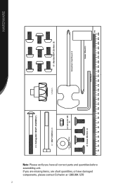
SW231 HARDWARE Note: Please verify you are missing items, are short quantities, or have all correct parts and quantities before assembling unit. If you have damaged components, please contact Schwinn at 1.800.864.1270 2 I-13 Carriage Bolt M8xP1.25x85MM (1) I-1 M8xP1.25x85mm I-2 Knob (1) I-5 Allen Bolt M8xP1.25x16mm (9) I-11 Regular Washer 10*25*2t(1) I-4 lock nut for M8 (1) Screwdriver I-6 Screws M8x16mm Socket Wrench���� Allen Key���� ����
SW231 HARDWARE Note: Please verify you are missing items, are short quantities, or have all correct parts and quantities before assembling unit. If you have damaged components, please contact Schwinn at 1.800.864.1270 2 I-13 Carriage Bolt M8xP1.25x85MM (1) I-1 M8xP1.25x85mm I-2 Knob (1) I-5 Allen Bolt M8xP1.25x16mm (9) I-11 Regular Washer 10*25*2t(1) I-4 lock nut for M8 (1) Screwdriver I-6 Screws M8x16mm Socket Wrench���� Allen Key���� ����
Assembly Manual
Page 4
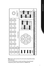
If you have damaged components, please contact Schwinn at 1.800.864.1270 3 I-3 Flat Washer 8*16*2t(20) I-12 Regular Washer 12.5*20*2t(1) I-8 Screw M5*16MM (4) I-10 Knob (1) I-7 Allen Bolt M8xP1.0x45mm (4) I-9 Allen Bolt M8xP1.0x35mm (5) ���� HARDWARE Note: Please verify you are missing items, are short quantities, or have all correct parts and quantities before assembling unit.
If you have damaged components, please contact Schwinn at 1.800.864.1270 3 I-3 Flat Washer 8*16*2t(20) I-12 Regular Washer 12.5*20*2t(1) I-8 Screw M5*16MM (4) I-10 Knob (1) I-7 Allen Bolt M8xP1.0x45mm (4) I-9 Allen Bolt M8xP1.0x35mm (5) ���� HARDWARE Note: Please verify you are missing items, are short quantities, or have all correct parts and quantities before assembling unit.
Assembly Manual
Page 6
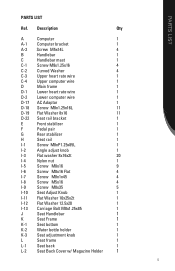
PARTS LIST PARTS LIST Ref. Description Qty A Computer 1 A-1 Computer bracket 1 A-2 Screw M5x14L 4 B Handlebar 1 C Handlebar mast 1 C-1 Screw M8x1.25x16 4 C-2 Curved Washer 4 C-3 Upper heart rate wire 1 C-4 Upper computer wire 1 D Main ...
PARTS LIST PARTS LIST Ref. Description Qty A Computer 1 A-1 Computer bracket 1 A-2 Screw M5x14L 4 B Handlebar 1 C Handlebar mast 1 C-1 Screw M8x1.25x16 4 C-2 Curved Washer 4 C-3 Upper heart rate wire 1 C-4 Upper computer wire 1 D Main ...
Assembly Manual
Page 8
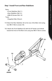
I-6 G I -6). 1-2 Attach the Front Stabilizer (E) with the UP sticker and wheels toward the front of the Main Unit using two M8 X 16mm screws. I-6) Tools: • Supplied Allen Wrench 1-1 Attach the Rear Stabilizer (G) to the rear of the Main Unit using two M8 X 16mm screws (I -6 E UP sticker 7 ASSEMBLY INSTRUCTIONS Step 1 Install Front and Rear Stabilizers Parts: • Front Stabilizer (Ref. E ) • Rear Stabilizer (Ref. G ) • M8x16 Screws (Ref.
I-6 G I -6). 1-2 Attach the Front Stabilizer (E) with the UP sticker and wheels toward the front of the Main Unit using two M8 X 16mm screws. I-6) Tools: • Supplied Allen Wrench 1-1 Attach the Rear Stabilizer (G) to the rear of the Main Unit using two M8 X 16mm screws (I -6 E UP sticker 7 ASSEMBLY INSTRUCTIONS Step 1 Install Front and Rear Stabilizers Parts: • Front Stabilizer (Ref. E ) • Rear Stabilizer (Ref. G ) • M8x16 Screws (Ref.
Assembly Manual
Page 9
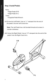
ASSEMBLY INSTRUCTIONS Step 2 Install Pedals Parts: • Right Pedal (F-R) • Right Pedal (F-L) Tools: • Supplied Pedal Wrench 2-1 Screw the Left Pedal ( has an "L" stamped into the end of the pedal ) into the Left Crank Arm. F-R F-L 8 Note: The Left Pedal has a left handed thread and screws in counter clockwise. 2-2 Screw the Right Pedal ( has an "R "stamped into the end of the pedal ) into the Right Crank Arm.
ASSEMBLY INSTRUCTIONS Step 2 Install Pedals Parts: • Right Pedal (F-R) • Right Pedal (F-L) Tools: • Supplied Pedal Wrench 2-1 Screw the Left Pedal ( has an "L" stamped into the end of the pedal ) into the Left Crank Arm. F-R F-L 8 Note: The Left Pedal has a left handed thread and screws in counter clockwise. 2-2 Screw the Right Pedal ( has an "R "stamped into the end of the pedal ) into the Right Crank Arm.
Assembly Manual
Page 10
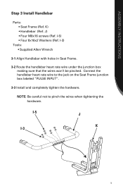
... the jack on the Seat Frame junction box labeled "PULSE INPUT". 3-3 Install and completely tighten the hardware. K) • Handlebar (Ref. I -3 9 ASSEMBLY INSTRUCTIONS Step 3 Install Handlebar Parts: • Seat Frame (Ref. I-5 J K I -3) Tools: • Supplied Allen Wrench 3-1 Align Handlebar with holes in Seat Frame. 3-2 Route the handlebar heart rate wire under the junction...
... the jack on the Seat Frame junction box labeled "PULSE INPUT". 3-3 Install and completely tighten the hardware. K) • Handlebar (Ref. I -3 9 ASSEMBLY INSTRUCTIONS Step 3 Install Handlebar Parts: • Seat Frame (Ref. I-5 J K I -3) Tools: • Supplied Allen Wrench 3-1 Align Handlebar with holes in Seat Frame. 3-2 Route the handlebar heart rate wire under the junction...

Assembly Manual
Page 11
K-1) Tools: • Supplied Phillips Head Screwdriver 4-1 Align the Water Bottle Holder under the left side of the Seat Bottom. 4-2 Install and completely tighten the hardware. K-2) • Four M5x16 Screws (Ref. K-1 K-2 I -8) • Seat Bottom (Ref. ASSEMBLY INSTRUCTIONS Step 4 Install Bottle Holder Parts: • Water Bottle Holder (Ref. I -8 10
K-1) Tools: • Supplied Phillips Head Screwdriver 4-1 Align the Water Bottle Holder under the left side of the Seat Bottom. 4-2 Install and completely tighten the hardware. K-2) • Four M5x16 Screws (Ref. K-1 K-2 I -8) • Seat Bottom (Ref. ASSEMBLY INSTRUCTIONS Step 4 Install Bottle Holder Parts: • Water Bottle Holder (Ref. I -8 10

Assembly Manual
Page 12
K-1 K I-3 I -3) Tools: • Supplied Allen Wrench 5-1 Align the Seat Bottom (K-1) with the Seat Frame (K). 5-2 Install and completely tighten the hardware. I -7 11 ASSEMBLY INSTRUCTIONS Step 5 Install Seat Bottom Parts: • Seat Bottom (Ref. K-1) • Four M8x1x45 Screws (Ref. I-7) • Four 8x16x2 Washers (Ref.
K-1 K I-3 I -3) Tools: • Supplied Allen Wrench 5-1 Align the Seat Bottom (K-1) with the Seat Frame (K). 5-2 Install and completely tighten the hardware. I -7 11 ASSEMBLY INSTRUCTIONS Step 5 Install Seat Bottom Parts: • Seat Bottom (Ref. K-1) • Four M8x1x45 Screws (Ref. I-7) • Four 8x16x2 Washers (Ref.
Assembly Manual
Page 13
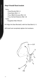
I -5 12 L-1 L I-3 I -3) Tools: • Supplied Allen Wrench 6-1 Align the Seat Bracket(L) with the Seat Back (L-1). 6-2 Install and completely tighten the hardware. ASSEMBLY INSTRUCTIONS Step 6 Install Seat bracket Parts: • Seat Bracket (Ref. I-5) • Four 8x16x2 Washers (Ref. L) • Seat Back (Ref L-1) • Four M8x16 Screws (Ref.
I -5 12 L-1 L I-3 I -3) Tools: • Supplied Allen Wrench 6-1 Align the Seat Bracket(L) with the Seat Back (L-1). 6-2 Install and completely tighten the hardware. ASSEMBLY INSTRUCTIONS Step 6 Install Seat bracket Parts: • Seat Bracket (Ref. I-5) • Four 8x16x2 Washers (Ref. L) • Seat Back (Ref L-1) • Four M8x16 Screws (Ref.
Assembly Manual
Page 14
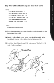
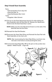
... Back Assy (From step 5) • Four M8x35 Screws (Ref. Threaded Post K L-2 L I-11 I-3 I-10 I-9 13 ASSEMBLY INSTRUCTIONS Step 7 Install Seat Back Assy and Seat Back Cover Parts: • Seat Back Cover (Ref.
... Back Assy (From step 5) • Four M8x35 Screws (Ref. Threaded Post K L-2 L I-11 I-3 I-10 I-9 13 ASSEMBLY INSTRUCTIONS Step 7 Install Seat Back Assy and Seat Back Cover Parts: • Seat Back Cover (Ref.
Assembly Manual
Page 16
... the Heart Rate Wire (M) to the jack on the junction box labeled "HAND PULSE". (Figure B) Figure B H M D-22 K-3 Figure A 15 ASSEMBLY INSTRUCTIONS Step 9 Install Seat Assembly Parts: • Seat Assembly (From step 3-6) • Seat Rail (Ref. H) • Seat Rail Bracket (Ref.
... the Heart Rate Wire (M) to the jack on the junction box labeled "HAND PULSE". (Figure B) Figure B H M D-22 K-3 Figure A 15 ASSEMBLY INSTRUCTIONS Step 9 Install Seat Assembly Parts: • Seat Assembly (From step 3-6) • Seat Rail (Ref. H) • Seat Rail Bracket (Ref.
Assembly Manual
Page 17
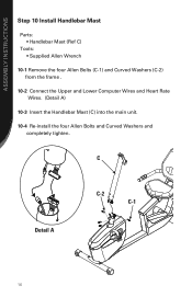
ASSEMBLY INSTRUCTIONS Step 10 Install Handlebar Mast Parts: • Handlebar Mast (Ref C) Tools: • Supplied Allen Wrench 10-1 Remove the four Allen Bolts (C-1) and Curved Washers (C-2) from the frame . 10-2 Connect the Upper and Lower Computer Wires and Heart Rate Wires. (Detail A) 10-3 Insert the Handlebar Mast (C) into the main unit. 10-4 Re-install the four Allen Bolts and Curved Washers and completely tighten. C Detail A C-2 C-1 16
ASSEMBLY INSTRUCTIONS Step 10 Install Handlebar Mast Parts: • Handlebar Mast (Ref C) Tools: • Supplied Allen Wrench 10-1 Remove the four Allen Bolts (C-1) and Curved Washers (C-2) from the frame . 10-2 Connect the Upper and Lower Computer Wires and Heart Rate Wires. (Detail A) 10-3 Insert the Handlebar Mast (C) into the main unit. 10-4 Re-install the four Allen Bolts and Curved Washers and completely tighten. C Detail A C-2 C-1 16

Assembly Manual
Page 18
ASSEMBLY INSTRUCTIONS Step 11 Install Handlebar Parts: • Handlebar (Ref B) • Washer (Ref I-3) • Screw M8x16 (Ref I-5) 11-1 Tuck the Computer Wires into the Mast to allow insertion of the Handlebar . 11-2 Slide the Handlebar (B) into the Mast and secure with the Console M8x16 Screw (I-5) and Washer (I-3) . (Figure A) 11-3 Pull the Computer Wires back up through the Handlebar as shown. (Figure B) B I-3 I-5 Figure B Figure A 17
ASSEMBLY INSTRUCTIONS Step 11 Install Handlebar Parts: • Handlebar (Ref B) • Washer (Ref I-3) • Screw M8x16 (Ref I-5) 11-1 Tuck the Computer Wires into the Mast to allow insertion of the Handlebar . 11-2 Slide the Handlebar (B) into the Mast and secure with the Console M8x16 Screw (I-5) and Washer (I-3) . (Figure A) 11-3 Pull the Computer Wires back up through the Handlebar as shown. (Figure B) B I-3 I-5 Figure B Figure A 17


