User Manual Ver.1.0 (English)
Page 1
To receive more complete service, please register your product at www.samsung.com/register Model Serial No E-MANUAL Thank you for purchasing this Samsung product.
To receive more complete service, please register your product at www.samsung.com/register Model Serial No E-MANUAL Thank you for purchasing this Samsung product.
User Manual Ver.1.0 (English)
Page 2
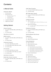
...Connections Digital Audio (Optical) Connection 14 For the LED 7450/7500, 8000 and PDP 8500 series models 14 For the S9 models Audio Output Connection 15 For the LED 7450/7500, 8000 series models 15 For the S9 models ARC (Audio Return Channel) 16 For the LED 7450/7500, 8000 and PDP 8500 series...to-DVI Connection 20 For the LED 7450/7500, 8000 and PDP 8500 series models 21 For the S9 models Smartphone Connection 22 For the LED 7450/7500, 8000 and PDP 8500 series models 23 For the S9 models Switching Between Video Sources Programming 25 Auto Program 25 Remove Scrambled Channels Channel Management ...
...Connections Digital Audio (Optical) Connection 14 For the LED 7450/7500, 8000 and PDP 8500 series models 14 For the S9 models Audio Output Connection 15 For the LED 7450/7500, 8000 series models 15 For the S9 models ARC (Audio Return Channel) 16 For the LED 7450/7500, 8000 and PDP 8500 series...to-DVI Connection 20 For the LED 7450/7500, 8000 and PDP 8500 series models 21 For the S9 models Smartphone Connection 22 For the LED 7450/7500, 8000 and PDP 8500 series models 23 For the S9 models Switching Between Video Sources Programming 25 Auto Program 25 Remove Scrambled Channels Channel Management ...
User Manual Ver.1.0 (English)
Page 3
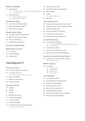
Network Configuration 32 Wired Network 32 For the LED 7450/7500, 8000 and PDP 8500 series models 33 For the S9 models 34 Wireless Network 34 Wireless Network Precautions 34 Network Security Protocols Wired Network Setup 35 Automatic Wired Network Setup 35 Manual Wired Network Setup 37 ... the virtual remote panel Universal Remote Setup 56 Connecting the IR Extender 56 For the LED 7450/7500, 8000 and PDP 8500 series models 57 For the S9 models 57 Add the External Device 57 Using the Universal Remote Control 57 Registered External Device Management Entering Text using the Onscreen Keypad 58...
Network Configuration 32 Wired Network 32 For the LED 7450/7500, 8000 and PDP 8500 series models 33 For the S9 models 34 Wireless Network 34 Wireless Network Precautions 34 Network Security Protocols Wired Network Setup 35 Automatic Wired Network Setup 35 Manual Wired Network Setup 37 ... the virtual remote panel Universal Remote Setup 56 Connecting the IR Extender 56 For the LED 7450/7500, 8000 and PDP 8500 series models 57 For the S9 models 57 Add the External Device 57 Using the Universal Remote Control 57 Registered External Device Management Entering Text using the Onscreen Keypad 58...
User Manual Ver.1.0 (English)
Page 10
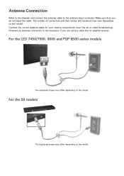
... cable to the antenna input connector. The number of connectors and their names and locations may differ depending on the model. For the S9 models The displayed image may vary depending on the model. Make sure that you are using a cable box or satellite receiver. For the LED 7450/7500, 8000 and PDP...
... cable to the antenna input connector. The number of connectors and their names and locations may differ depending on the model. For the S9 models The displayed image may vary depending on the model. Make sure that you are using a cable box or satellite receiver. For the LED 7450/7500, 8000 and PDP...
User Manual Ver.1.0 (English)
Page 11
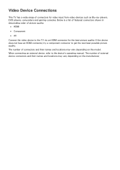
The number of external device connectors and their names and locations may vary depending on the model. When connecting an external device, refer to get the next best possible picture quality. The number of connectors and their names and locations may vary ...
The number of external device connectors and their names and locations may vary depending on the model. When connecting an external device, refer to get the next best possible picture quality. The number of connectors and their names and locations may vary ...

User Manual Ver.1.0 (English)
Page 12
... result in a blank screen or a connection error. One of 14 mm or less. HDMI Connection For the LED 7450/7500, 8000 and PDP 8500 series models Refer to the diagram and connect the HDMI cable to different HDMI specifications. "" Some HDMI cables and devices may not be compatible with a thickness of...
... result in a blank screen or a connection error. One of 14 mm or less. HDMI Connection For the LED 7450/7500, 8000 and PDP 8500 series models Refer to the diagram and connect the HDMI cable to different HDMI specifications. "" Some HDMI cables and devices may not be compatible with a thickness of...

User Manual Ver.1.0 (English)
Page 13
For the S9 models Refer to the diagram and connect the HDMI cable to different HDMI specifications. "" Some HDMI cables and devices may not be compatible with a thickness of .... One of 14 mm or less. "" This TV does not support the HDMI Ethernet Channel. Using a non-certified HDMI cable may differ depending on the model.
For the S9 models Refer to the diagram and connect the HDMI cable to different HDMI specifications. "" Some HDMI cables and devices may not be compatible with a thickness of .... One of 14 mm or less. "" This TV does not support the HDMI Ethernet Channel. Using a non-certified HDMI cable may differ depending on the model.
User Manual Ver.1.0 (English)
Page 14
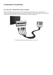
The displayed image may differ depending on the model. Component Connection For the LED 7450/7500 series models Refer to the diagram and connect the TV's component video and audio input connectors to the external device's component video and audio output connectors using a component cable, so that the connectors of the same color connect to each other, as shown in the figure.
The displayed image may differ depending on the model. Component Connection For the LED 7450/7500 series models Refer to the diagram and connect the TV's component video and audio input connectors to the external device's component video and audio output connectors using a component cable, so that the connectors of the same color connect to each other, as shown in the figure.
User Manual Ver.1.0 (English)
Page 15
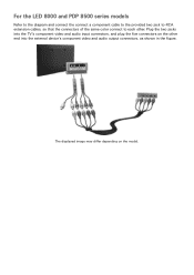
Plug the two jacks into the external device's component video and audio output connectors, as shown in the figure. For the LED 8000 and PDP 8500 series models Refer to the diagram and connect the connect a component cable to the provided two jack to-RCA extension cables, so that the connectors of the same color connect to each other end into the TV's component video and audio input connectors, and plug the five connectors on the model. The displayed image may differ depending on the other .
Plug the two jacks into the external device's component video and audio output connectors, as shown in the figure. For the LED 8000 and PDP 8500 series models Refer to the diagram and connect the connect a component cable to the provided two jack to-RCA extension cables, so that the connectors of the same color connect to each other end into the TV's component video and audio input connectors, and plug the five connectors on the model. The displayed image may differ depending on the other .
User Manual Ver.1.0 (English)
Page 16
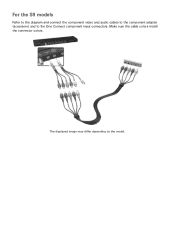
For the S9 models Refer to the diagram and connect the component video and audio cables to the component adapter (accessory) and to the One Connect component input connectors. Make sure the cable colors match the connector colors. The displayed image may differ depending on the model.
For the S9 models Refer to the diagram and connect the component video and audio cables to the component adapter (accessory) and to the One Connect component input connectors. Make sure the cable colors match the connector colors. The displayed image may differ depending on the model.
User Manual Ver.1.0 (English)
Page 17
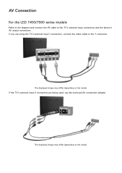
If the TV's external input 2 connectors are using the TV's external input 1 connectors, connect the video cable to the TV's external input connectors and the device's AV output connectors. The displayed image may differ depending on the model. The displayed image may differ depending on the model. If you are being used, use the enclosed AV connection adapter. AV Connection For the LED 7450/7500 series models Refer to the diagram and connect the AV cable to the Y connector.
If the TV's external input 2 connectors are using the TV's external input 1 connectors, connect the video cable to the TV's external input connectors and the device's AV output connectors. The displayed image may differ depending on the model. The displayed image may differ depending on the model. If you are being used, use the enclosed AV connection adapter. AV Connection For the LED 7450/7500 series models Refer to the diagram and connect the AV cable to the Y connector.
User Manual Ver.1.0 (English)
Page 18
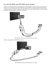
The displayed image may differ depending on the model. Plug the jack into the external device's composite video and audio output connectors, as shown in LED 8000 Series only. AV IN 2 is supported in the figure. For the LED 8000 and PDP 8500 series models Connect a composite cable to the provided jack-to-RCA extension cable, so that the connectors of the same color connect to each other end into the TV's composite video and audio input connector, and plug the three connectors on the model. The displayed image may differ depending on the other .
The displayed image may differ depending on the model. Plug the jack into the external device's composite video and audio output connectors, as shown in LED 8000 Series only. AV IN 2 is supported in the figure. For the LED 8000 and PDP 8500 series models Connect a composite cable to the provided jack-to-RCA extension cable, so that the connectors of the same color connect to each other end into the TV's composite video and audio input connector, and plug the three connectors on the model. The displayed image may differ depending on the other .

User Manual Ver.1.0 (English)
Page 19
The displayed image may differ depending on the model. For the S9 models Refer to the diagram and connect the video and audio cables to the A/V adapter (included) and the adapter to One Connect's external input 1 or 2 connector.
The displayed image may differ depending on the model. For the S9 models Refer to the diagram and connect the video and audio cables to the A/V adapter (included) and the adapter to One Connect's external input 1 or 2 connector.
User Manual Ver.1.0 (English)
Page 20
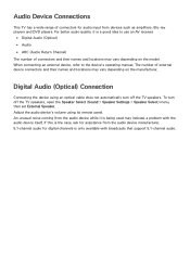
... Audio (Optical) ●● Audio ●● ARC (Audio Return Channel) The number of connectors and their names and locations may vary depending on the model. If this is the case, ask for assistance from the audio device manufacturer. 5.1-channel audio for audio input from the audio device while it is...
... Audio (Optical) ●● Audio ●● ARC (Audio Return Channel) The number of connectors and their names and locations may vary depending on the model. If this is the case, ask for assistance from the audio device manufacturer. 5.1-channel audio for audio input from the audio device while it is...

User Manual Ver.1.0 (English)
Page 21
For the S9 models Refer to the diagram and connect the optical cable to the TV's digital audio output connector and the device's digital audio input connector. For the LED 7450/7500, 8000 and PDP 8500 series models Refer to the diagram and connect the optical cable to the One Connect digital audio output connector and the device's digital audio input connector. The displayed image may differ depending on the model. The displayed image may differ depending on the model.
For the S9 models Refer to the diagram and connect the optical cable to the TV's digital audio output connector and the device's digital audio input connector. For the LED 7450/7500, 8000 and PDP 8500 series models Refer to the diagram and connect the optical cable to the One Connect digital audio output connector and the device's digital audio input connector. The displayed image may differ depending on the model. The displayed image may differ depending on the model.

User Manual Ver.1.0 (English)
Page 22
For the S9 models Refer to the diagram and connect the audio cable to the TV's audio output connector and the device's audio input connector. Audio Output Connection For the LED 7450/7500, 8000 series models Refer to the diagram and connect the audio cable to the One Connect audio output connector and the device's audio input connector. The displayed image may differ depending on the model. The displayed image may differ depending on the model.
For the S9 models Refer to the diagram and connect the audio cable to the TV's audio output connector and the device's audio input connector. Audio Output Connection For the LED 7450/7500, 8000 series models Refer to the diagram and connect the audio cable to the One Connect audio output connector and the device's audio input connector. The displayed image may differ depending on the model. The displayed image may differ depending on the model.
User Manual Ver.1.0 (English)
Page 23
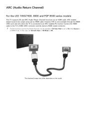
... TV supports 3D and ARC (Audio Return Channel) functions via an HDMI cable. "" Certain functions such as the Smart Hub may differ depending on the model. In this case, set to On while Source is connected to be available if 3D Auto View is set 3D Auto View or 3D Mode...
... TV supports 3D and ARC (Audio Return Channel) functions via an HDMI cable. "" Certain functions such as the Smart Hub may differ depending on the model. In this case, set to On while Source is connected to be available if 3D Auto View is set 3D Auto View or 3D Mode...
User Manual Ver.1.0 (English)
Page 24
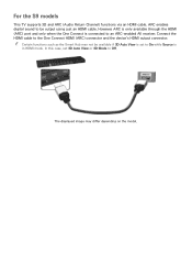
... to an ARC-enabled AV receiver. "" Certain functions such as the Smart Hub may differ depending on the model. The displayed image may not be output using just an HDMI cable. For the S9 models This TV supports 3D and ARC (Audio Return Channel) functions via an HDMI cable. In this case...
... to an ARC-enabled AV receiver. "" Certain functions such as the Smart Hub may differ depending on the model. The displayed image may not be output using just an HDMI cable. For the S9 models This TV supports 3D and ARC (Audio Return Channel) functions via an HDMI cable. In this case...

User Manual Ver.1.0 (English)
Page 25
HDMI Connection For the LED 7450/7500, 8000 and PDP 8500 series models Refer to the diagram and connect the HDMI cable to the TV. In this case, use an HDMI-to-DVI cable to connect the computer to the TV's HDMI input port and the computer's HDMI output port. The displayed image may differ depending on the resolution settings supported to the "Display Resolution" for connect the computer. Not all computers are HDMI-enabled. Refer to the TV. Computer Connection This TV supports the HDMI/DVI port for information on the model.
HDMI Connection For the LED 7450/7500, 8000 and PDP 8500 series models Refer to the diagram and connect the HDMI cable to the TV. In this case, use an HDMI-to-DVI cable to connect the computer to the TV's HDMI input port and the computer's HDMI output port. The displayed image may differ depending on the resolution settings supported to the "Display Resolution" for connect the computer. Not all computers are HDMI-enabled. Refer to the TV. Computer Connection This TV supports the HDMI/DVI port for information on the model.
User Manual Ver.1.0 (English)
Page 26
For the S9 models Refer to the diagram and connect the HDMI cable to the One Connect HDMI input port and the computer's HDMI output port. The displayed image may differ depending on the model.
For the S9 models Refer to the diagram and connect the HDMI cable to the One Connect HDMI input port and the computer's HDMI output port. The displayed image may differ depending on the model.


