

User Manual (user Manual) (ver.1.0) (English)
Page 1
TXN2771HF/TXN3071WHF TXN3271HF/TXN2798HF TXN3098WHF/TXN3298HF TXN2775HF/TXN3075WHF TXN3275HF/TXN2670WHF TXN2745FP/TXN3245FP TXN3234HF COLOR TELEVISION SERVICE DIVISION 400 Valley Road, Suite 201 Mount Arlington, NJ 07856 TEL: 1-800-SAMSUNG (1-800-726-7864) www.samsungusa.com AA68-02942A-00 Owner's Instructions ...
TXN2771HF/TXN3071WHF TXN3271HF/TXN2798HF TXN3098WHF/TXN3298HF TXN2775HF/TXN3075WHF TXN3275HF/TXN2670WHF TXN2745FP/TXN3245FP TXN3234HF COLOR TELEVISION SERVICE DIVISION 400 Valley Road, Suite 201 Mount Arlington, NJ 07856 TEL: 1-800-SAMSUNG (1-800-726-7864) www.samsungusa.com AA68-02942A-00 Owner's Instructions ...
User Manual (user Manual) (ver.1.0) (English)
Page 2
... TV programs is present inside part of plug to make any kind of contact with this appliance to operate it. As an ENERGY STAR Partner, Samsung Electronics America, Inc. Note to CATV system installer: This reminder is dangerous to the wide slot, and fully insert the plug. Important: One Federal Court...
... TV programs is present inside part of plug to make any kind of contact with this appliance to operate it. As an ENERGY STAR Partner, Samsung Electronics America, Inc. Note to CATV system installer: This reminder is dangerous to the wide slot, and fully insert the plug. Important: One Federal Court...
User Manual (user Manual) (ver.1.0) (English)
Page 3
...mounting accessory recommended by the manufacturer or sold with a cart, stand, tripod, bracket, or table recommended by the manufacturer. Thank You for Choosing Samsung Thank you for mounting. • Operate your TV receiver only from the type of power source indicated on an unstable cart, stand, tripod, bracket...is adequate ventilation and that will fit into the outlet, try reversing the plug. If you 've followed the manufacturer's instructions for choosing Samsung! We designed it one way. We are not sure of the type of fire, electric shock, or other . Move the TV and...
...mounting accessory recommended by the manufacturer or sold with a cart, stand, tripod, bracket, or table recommended by the manufacturer. Thank You for Choosing Samsung Thank you for mounting. • Operate your TV receiver only from the type of power source indicated on an unstable cart, stand, tripod, bracket...is adequate ventilation and that will fit into the outlet, try reversing the plug. If you 've followed the manufacturer's instructions for choosing Samsung! We designed it one way. We are not sure of the type of fire, electric shock, or other . Move the TV and...
User Manual (user Manual) (ver.1.0) (English)
Page 4
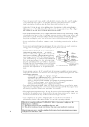
This will often require extensive work by a qualified technician to restore the TV to provide some protection against them. An outside antenna system should be walked on the unit or if objects have the same characteristics as to normal. • When replacement parts are required, be sure the service technician uses replacement parts specified by the manufacturer or those controls that have fallen into such power lines or circuits. Overloading can fall into the unit - NATIONAL ELECTRICAL CODE ANTENNA LEAD IN WIRE ANTENNA DISCHARGE UNIT (NEC SECTION 810-20) GROUNDING ...
This will often require extensive work by a qualified technician to restore the TV to provide some protection against them. An outside antenna system should be walked on the unit or if objects have the same characteristics as to normal. • When replacement parts are required, be sure the service technician uses replacement parts specified by the manufacturer or those controls that have fallen into such power lines or circuits. Overloading can fall into the unit - NATIONAL ELECTRICAL CODE ANTENNA LEAD IN WIRE ANTENNA DISCHARGE UNIT (NEC SECTION 810-20) GROUNDING ...
User Manual (user Manual) (ver.1.0) (English)
Page 5
... images displayed on them should primarily be in the selection and duration of format selection and use these controls to fill the screen if your Samsung limited warranty. 5 The images displayed on them should primarily be limited as a full screen picture. Be careful in the wide screen 16:9 ratio format, or...
... images displayed on them should primarily be in the selection and duration of format selection and use these controls to fill the screen if your Samsung limited warranty. 5 The images displayed on them should primarily be limited as a full screen picture. Be careful in the wide screen 16:9 ratio format, or...
User Manual (user Manual) (ver.1.0) (English)
Page 6
CONTENTS Chapter 1: Your New TV 8 List of Features 8 Familiarizing Yourself with The TV 9 Front Panel Buttons 9 Side Panel Jacks 10 Rear Panel Jacks 11 Remote Control 12 Chapter 2: Installation 14 Connecting VHF and UHF Antennas 14 Antennas with 300-ohm Flat Twin Leads 14 Antennas with 75-ohm Round Leads 15 Separate VHF and UHF Antennas 15 Connecting Cable TV 15 Cable without a Cable Box 15 Connecting to a Cable Box that Descrambles All Channels . . . . 16 Connecting to a Cable Box that Descrambles Some Channels. . . . . 16 Connecting a VCR 18 Connecting an S-VHS VCR 19 ...
CONTENTS Chapter 1: Your New TV 8 List of Features 8 Familiarizing Yourself with The TV 9 Front Panel Buttons 9 Side Panel Jacks 10 Rear Panel Jacks 11 Remote Control 12 Chapter 2: Installation 14 Connecting VHF and UHF Antennas 14 Antennas with 300-ohm Flat Twin Leads 14 Antennas with 75-ohm Round Leads 15 Separate VHF and UHF Antennas 15 Connecting Cable TV 15 Cable without a Cable Box 15 Connecting to a Cable Box that Descrambles All Channels . . . . 16 Connecting to a Cable Box that Descrambles Some Channels. . . . . 16 Connecting a VCR 18 Connecting an S-VHS VCR 19 ...
User Manual (user Manual) (ver.1.0) (English)
Page 7
CONTENTS Chapter 4: Special Features 42 Customizing Your Remote Control 42 Setting Up Your Remote Control to Operate Your VCR (or DVD) . . 42 Setting Up Your Remote Control to Operate Your Cable Box . . . . . 44 Fine Tuning Channels 45 LNA (Low Noise Amplifier 46 Tilt 47 DNIeTM (Digital Natural Image engine 48 Digital Noise Reduction 49 Changing the Screen Size 50 Changing the Color Tone 51 Using the R.Surf Feature 52 Freezing the Picture 52 Setting the On/Off Timer 53 Setting the Sleep Timer 54 Choosing a Multi-Channel Sound (MTS) Soundtrack 55 Extra sound settings (Turbo Sound,...
CONTENTS Chapter 4: Special Features 42 Customizing Your Remote Control 42 Setting Up Your Remote Control to Operate Your VCR (or DVD) . . 42 Setting Up Your Remote Control to Operate Your Cable Box . . . . . 44 Fine Tuning Channels 45 LNA (Low Noise Amplifier 46 Tilt 47 DNIeTM (Digital Natural Image engine 48 Digital Noise Reduction 49 Changing the Screen Size 50 Changing the Color Tone 51 Using the R.Surf Feature 52 Freezing the Picture 52 Setting the On/Off Timer 53 Setting the Sleep Timer 54 Choosing a Multi-Channel Sound (MTS) Soundtrack 55 Extra sound settings (Turbo Sound,...
User Manual (user Manual) (ver.1.0) (English)
Page 8
Chapter One YOUR NEW TV List of Features Your TV was designed with the latest technology. This TV is a high-performance unit that includes the following special features: • Full Flat Screen • Easy-to-use remote control • Easy-to-use on-screen menu system • Automatic timer to turn the TV on and off • Adjustable picture and sound settings that can be stored in the TV's memory • Automatic channel tuning for up to 181 channels • A special filter to reduce or eliminate reception problems • Fine tuning control for the sharpest picture possible •...
Chapter One YOUR NEW TV List of Features Your TV was designed with the latest technology. This TV is a high-performance unit that includes the following special features: • Full Flat Screen • Easy-to-use remote control • Easy-to-use on-screen menu system • Automatic timer to turn the TV on and off • Adjustable picture and sound settings that can be stored in the TV's memory • Automatic channel tuning for up to 181 channels • A special filter to reduce or eliminate reception problems • Fine tuning control for the sharpest picture possible •...
User Manual (user Manual) (ver.1.0) (English)
Page 9
... on -screen menu. Is the Power Plug correctly connect- To use the more advanced features, you use the remote control. • TXN2771HF • TXN3271HF • TXN3071WHF The Touch Switch does not run. 1. Press the Touch Switch softly if it does not work properly. • TXN2670WHF • TXN2798HF • TXN3298HF • TXN3098WHF...
... on -screen menu. Is the Power Plug correctly connect- To use the more advanced features, you use the remote control. • TXN2771HF • TXN3271HF • TXN3071WHF The Touch Switch does not run. 1. Press the Touch Switch softly if it does not work properly. • TXN2670WHF • TXN2798HF • TXN3298HF • TXN3098WHF...
User Manual (user Manual) (ver.1.0) (English)
Page 10
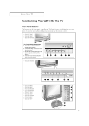
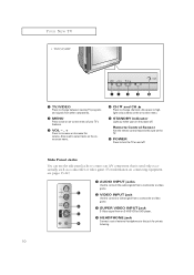
Remote Control Sensor Aim the remote control towards this jack for private listening. 10 YOUR NEW TV • TXN3234HF Œ TV/VIDEO Press to change channels. Also press to highlight various items on the on-screen menu. ˆ STANDBY indicator Lights up when you turn the TV on -screen menu of external headphones to increase or decrease the volume. Also used only occasionally, such as a camcorder or video game. (For information on connecting equipment, see pages 13-22.) Œ AUDIO INPUT jacks Used to connect the audio signals from a camcorder or video game. ´ VIDEO INPUT...
Remote Control Sensor Aim the remote control towards this jack for private listening. 10 YOUR NEW TV • TXN3234HF Œ TV/VIDEO Press to change channels. Also press to highlight various items on the on-screen menu. ˆ STANDBY indicator Lights up when you turn the TV on -screen menu of external headphones to increase or decrease the volume. Also used only occasionally, such as a camcorder or video game. (For information on connecting equipment, see pages 13-22.) Œ AUDIO INPUT jacks Used to connect the audio signals from a camcorder or video game. ´ VIDEO INPUT...
User Manual (user Manual) (ver.1.0) (English)
Page 11
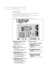
YOUR NEW TV Rear Panel Jacks Use the rear panel jacks to the audio and component output jacks of a DVD player or Set-Top Box. Note: Only black and white signals are exclusive relation with each other. ˇ COMPONENT 1 INPUT jacks (480i/480p/1080i) Connect to a cable TV system. Note: The common jack of component 1 and AV2, component 2 and AV3 input jacks are output from a monitor in Sub-woofer cable). ' DVI AUDIO INPUT jacks (TXN3298HF/TXN3098WHF/ TXN2798HF) Receives the digital audio signals from a set top box. ˝ DIGITAL INPUT (Digital Visual Interface) jack (TXN3298HF/...
YOUR NEW TV Rear Panel Jacks Use the rear panel jacks to the audio and component output jacks of a DVD player or Set-Top Box. Note: Only black and white signals are exclusive relation with each other. ˇ COMPONENT 1 INPUT jacks (480i/480p/1080i) Connect to a cable TV system. Note: The common jack of component 1 and AV2, component 2 and AV3 input jacks are output from a monitor in Sub-woofer cable). ' DVI AUDIO INPUT jacks (TXN3298HF/TXN3098WHF/ TXN2798HF) Receives the digital audio signals from a set top box. ˝ DIGITAL INPUT (Digital Visual Interface) jack (TXN3298HF/...
User Manual (user Manual) (ver.1.0) (English)
Page 12
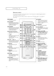
...SURF button to automatically return to a preferred channel after a user-preset time delay. Ô MODE Selects a target device to be controlled by the Samsung remote control (i.e., TV, Set Top Box, VCR, Cable box, or DVD). PRE-CH Tunes to the previous channel. Ò TV...AV2, AV3, S-VIDEO). Ú CHL and CHM (Channel Up/Down) Press CHL or CHM to change ) a particular item. ¯ TURBO (TXN2771HF/TXN3071WHF/ TXN3271HF/TXN2670WHF/ TXN2775HF/TXN3275HF/ TXN3075WHF/TXN2745FP/ TXN3245FP/TXN3234HF) Press to turn the TURBO sound On or Off. ˘ MTS (Multichannel Television Stereo) Press to...
...SURF button to automatically return to a preferred channel after a user-preset time delay. Ô MODE Selects a target device to be controlled by the Samsung remote control (i.e., TV, Set Top Box, VCR, Cable box, or DVD). PRE-CH Tunes to the previous channel. Ò TV...AV2, AV3, S-VIDEO). Ú CHL and CHM (Channel Up/Down) Press CHL or CHM to change ) a particular item. ¯ TURBO (TXN2771HF/TXN3071WHF/ TXN3271HF/TXN2670WHF/ TXN2775HF/TXN3275HF/ TXN3075WHF/TXN2745FP/ TXN3245FP/TXN3234HF) Press to turn the TURBO sound On or Off. ˘ MTS (Multichannel Television Stereo) Press to...
User Manual (user Manual) (ver.1.0) (English)
Page 13
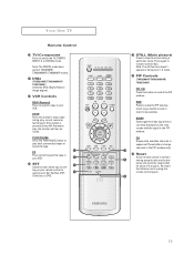
STOP Press this button to control the PIP window. PLAY/PAUSE Press the PLAY/PAUSE button to resume normal video. Reset If your Set Top Box, VCR, Cable box, or DVD. ± STILL (Main picture) Press to stop the action during a particular scene. Press again to play , record, rewind or fast forward. Note: The still function doesn't operate in your VCR. SIZE Press to switch the TV, COMPONENT1, 2, or DIGITAL mode. YOUR NEW TV Remote Control ¿ TV/Component Press to make the PIP window small, large, double screen or stock ticker window. If the button is pressed ...
STOP Press this button to control the PIP window. PLAY/PAUSE Press the PLAY/PAUSE button to resume normal video. Reset If your Set Top Box, VCR, Cable box, or DVD. ± STILL (Main picture) Press to stop the action during a particular scene. Press again to play , record, rewind or fast forward. Note: The still function doesn't operate in your VCR. SIZE Press to switch the TV, COMPONENT1, 2, or DIGITAL mode. YOUR NEW TV Remote Control ¿ TV/Component Press to make the PIP window small, large, double screen or stock ticker window. If the button is pressed ...
User Manual (user Manual) (ver.1.0) (English)
Page 14
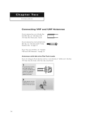
Antennas with 300-ohm Flat Twin Leads If you have two antennas, see "Separate VHF and UHF Antennas," on the 300-75 ohm adaptor (not supplied). Use a screwdriver to tighten the screws. 2 Plug the adaptor into the VHF/UHF terminal on the bottom of leads that look like this , see "Antennas with 300-ohm Flat Twin Leads," below . 1 Place the wires from the twin leads under the screws on page 15. If you are using an off-air antenna (such as a roof antenna or "rabbit ears") that has 300-ohm twin flat leads, follow the directions below . If your antenna has a set of the back panel. 14 2 ...
Antennas with 300-ohm Flat Twin Leads If you have two antennas, see "Separate VHF and UHF Antennas," on the 300-75 ohm adaptor (not supplied). Use a screwdriver to tighten the screws. 2 Plug the adaptor into the VHF/UHF terminal on the bottom of leads that look like this , see "Antennas with 300-ohm Flat Twin Leads," below . 1 Place the wires from the twin leads under the screws on page 15. If you are using an off-air antenna (such as a roof antenna or "rabbit ears") that has 300-ohm twin flat leads, follow the directions below . If your antenna has a set of the back panel. 14 2 ...

User Manual (user Manual) (ver.1.0) (English)
Page 15
Connecting Cable TV To connect to the combiner. 2 Plug the combiner into the VHF/UHF terminal on the bottom of the rear panel. M Because this TV is cable-ready, you must combine the two antenna signals before connecting the antennas to view unscrambled cable channels. 15 Separate VHF and UHF Antennas If you have two separate antennas for your TV (one VHF and one UHF), you do not need a cable box to the TV. INSTALLATION Antennas with 75-ohm Round Leads 1 Plug the antenna lead into the VHF/UHF terminal on the bottom of the TV. Cable without a Cable Box 1 Plug the incoming ...
Connecting Cable TV To connect to the combiner. 2 Plug the combiner into the VHF/UHF terminal on the bottom of the rear panel. M Because this TV is cable-ready, you must combine the two antenna signals before connecting the antennas to view unscrambled cable channels. 15 Separate VHF and UHF Antennas If you have two separate antennas for your TV (one VHF and one UHF), you do not need a cable box to the TV. INSTALLATION Antennas with 75-ohm Round Leads 1 Plug the antenna lead into the VHF/UHF terminal on the bottom of the TV. Cable without a Cable Box 1 Plug the incoming ...

User Manual (user Manual) (ver.1.0) (English)
Page 16
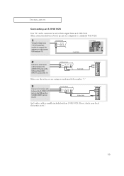
M This terminal might be labeled "ANT OUT," "VHF OUT," or simply, "OUT." 2 Connect the other end of this cable to a two-way splitter. 3 Connect a coaxial cable between an OUTPUT terminal on the splitter and the IN terminal on the back of coaxial cable. (These items are available at most electronics stores.) 1 Find and disconnect the cable that is connected to the ANTENNA OUT terminal on your cable box descrambles only some channels (such as premium channels), follow the instructions below. M This terminal might be labeled "ANT IN," "VHF IN," or simply, "IN." 2 Connect this ...
M This terminal might be labeled "ANT OUT," "VHF OUT," or simply, "OUT." 2 Connect the other end of this cable to a two-way splitter. 3 Connect a coaxial cable between an OUTPUT terminal on the splitter and the IN terminal on the back of coaxial cable. (These items are available at most electronics stores.) 1 Find and disconnect the cable that is connected to the ANTENNA OUT terminal on your cable box descrambles only some channels (such as premium channels), follow the instructions below. M This terminal might be labeled "ANT IN," "VHF IN," or simply, "IN." 2 Connect this ...

User Manual (user Manual) (ver.1.0) (English)
Page 17
After you've made this connection, set the A/B switch to "B," you set the A/B switch to the cable box's output channel, which is usually channel 3 or 4.) 17 Set the A/B switch to the "B" position to view scrambled channels. (When you will need to tune your TV to the "A" position for normal viewing. INSTALLATION 4 Connect a coaxial cable between the ANTENNA OUT terminal on the cable box and the B-IN terminal on the A/B switch. 5 Connect another cable between the other OUT terminal on the splitter and the A-IN terminal on the RF (A/B) switch. 6 Connect the last coaxial cable between ...
After you've made this connection, set the A/B switch to "B," you set the A/B switch to the cable box's output channel, which is usually channel 3 or 4.) 17 Set the A/B switch to the "B" position to view scrambled channels. (When you will need to tune your TV to the "A" position for normal viewing. INSTALLATION 4 Connect a coaxial cable between the ANTENNA OUT terminal on the cable box and the B-IN terminal on the A/B switch. 5 Connect another cable between the other OUT terminal on the splitter and the A-IN terminal on the RF (A/B) switch. 6 Connect the last coaxial cable between ...

User Manual (user Manual) (ver.1.0) (English)
Page 18
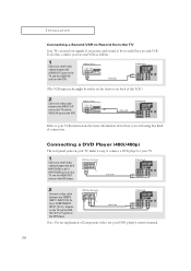
Follow the instructions in "Viewing a VCR or Camcorder Tape" to view your local electronics store). 4 Connect a set of audio cables between the VIDEO OUT jack on the VCR and the VIDEO jack(AV1~AV3) on the TV. A coaxial cable is stereo, you have not yet connected to an antenna or a cable system. 1 Unplug the cable or antenna from the back of the TV. 2 Connect the cable or antenna to the ANTENNA IN terminal on the back of the VCR. 3 Connect a coaxial cable between the ANTENNA OUT terminal on the VCR and the antenna terminal on the TV. INSTALLATION Connecting a VCR These instructions ...
Follow the instructions in "Viewing a VCR or Camcorder Tape" to view your local electronics store). 4 Connect a set of audio cables between the VIDEO OUT jack on the VCR and the VIDEO jack(AV1~AV3) on the TV. A coaxial cable is stereo, you have not yet connected to an antenna or a cable system. 1 Unplug the cable or antenna from the back of the TV. 2 Connect the cable or antenna to the ANTENNA IN terminal on the back of the VCR. 3 Connect a coaxial cable between the ANTENNA OUT terminal on the VCR and the antenna terminal on the TV. INSTALLATION Connecting a VCR These instructions ...
User Manual (user Manual) (ver.1.0) (English)
Page 19
An S-video cable is usually included with an S-VHS VCR. (If not, check your TV. 2 Connect a set of audio cables between the S-VIDEO OUT jack on the VCR and the S-VIDEO INPUT jack on the TV. INSTALLATION Connecting an S-VHS VCR Your TV can be connected to an S-Video signal from an S-VHS VCR. (This connection delivers a better picture as compared to a standard VHS VCR.) 1 To begin, follow steps 1-3 in the previous section to connect the antenna or cable to your VCR and your local electronics store.) 19 Make sure the jacks you are using are underneath the number "1." 3 Connect an S-video ...
An S-video cable is usually included with an S-VHS VCR. (If not, check your TV. 2 Connect a set of audio cables between the S-VIDEO OUT jack on the VCR and the S-VIDEO INPUT jack on the TV. INSTALLATION Connecting an S-VHS VCR Your TV can be connected to an S-Video signal from an S-VHS VCR. (This connection delivers a better picture as compared to a standard VHS VCR.) 1 To begin, follow steps 1-3 in the previous section to connect the antenna or cable to your VCR and your local electronics store.) 19 Make sure the jacks you are using are underneath the number "1." 3 Connect an S-video ...
User Manual (user Manual) (ver.1.0) (English)
Page 20
Connecting a DVD Player (480i/480p) The rear panel jacks on your TV make it easy to connect a DVD player to your TV. 1 Connect a set of audio cables between the AUDIO OUT jacks on the TV and the AUDIO IN jacks on the VCR. (The VCR input jacks might be recorded by a second VCR. Note: For an explanation of Component video, see your second VCR as follows: 1 Connect a set of audio cables between the AV-2 INPUT(VCR) or AV-3 INPUT(VCR) jacks on the TV and the AUDIO OUT jacks on the DVD player. 2 Connect a video cable between the COMPONENT 1 INPUT (Y/V, PB, PR) or COMPONENT 2 INPUT (Y/V, PB, PR...
Connecting a DVD Player (480i/480p) The rear panel jacks on your TV make it easy to connect a DVD player to your TV. 1 Connect a set of audio cables between the AUDIO OUT jacks on the TV and the AUDIO IN jacks on the VCR. (The VCR input jacks might be recorded by a second VCR. Note: For an explanation of Component video, see your second VCR as follows: 1 Connect a set of audio cables between the AV-2 INPUT(VCR) or AV-3 INPUT(VCR) jacks on the TV and the AUDIO OUT jacks on the DVD player. 2 Connect a video cable between the COMPONENT 1 INPUT (Y/V, PB, PR) or COMPONENT 2 INPUT (Y/V, PB, PR...