User Manual
Page 1
English Network Camera SNB-5000/SND-5080/SND-5080F/SNV-5080 User Manual Before installing and operating this product, please read this manual thoroughly.
English Network Camera SNB-5000/SND-5080/SND-5080F/SNV-5080 User Manual Before installing and operating this product, please read this manual thoroughly.
User Manual
Page 4
... of an approved agency is used outside of the U.S., it 's defected. CAUTION These servicing instructions are qualified to monitor the installation process of the network camera. When used to do not perform any servicing other than that contained in your location.
... of an approved agency is used outside of the U.S., it 's defected. CAUTION These servicing instructions are qualified to monitor the installation process of the network camera. When used to do not perform any servicing other than that contained in your location.
User Manual
Page 7
...) 21 At a Glance (SNV-5080) INSTALLATION & CONNECTION 24 24 Installation (SND-5080) 26 Installation (SND-5080F) 28 Installation (SNV-5080) 32 Mounting the Lens 33 Inserting/Removing an SD Memory Card 36 Memory Card Information (Not Included) 37 Connecting with other Device NETWORK CONNECTION AND SETUP 42 42 Connecting the Camera Directly to Local Area Networking...
...) 21 At a Glance (SNV-5080) INSTALLATION & CONNECTION 24 24 Installation (SND-5080) 26 Installation (SND-5080F) 28 Installation (SNV-5080) 32 Mounting the Lens 33 Inserting/Removing an SD Memory Card 36 Memory Card Information (Not Included) 37 Connecting with other Device NETWORK CONNECTION AND SETUP 42 42 Connecting the Camera Directly to Local Area Networking...
User Manual
Page 8
overview CAMERA SETUP 53 53 How to use the Menu Key 53 Camera Menu Setup WEB VIEWER 62 62 Connecting to the Camera 63 Login 64 Installing Silverlight Runtime 66 Using the Live Screen 67 Using OSD Screen Menu 68 Playback SETUP SCREEN 70 70 Setup 70 Audio & Video Setup 73 Network Setup 77 Event Setup 83 System Setup APPENDIX 87 87 Camera Specification 89 Network Specification 91 Troubleshooting 93 GPL/LGPL Software License 8_ overview
overview CAMERA SETUP 53 53 How to use the Menu Key 53 Camera Menu Setup WEB VIEWER 62 62 Connecting to the Camera 63 Login 64 Installing Silverlight Runtime 66 Using the Live Screen 67 Using OSD Screen Menu 68 Playback SETUP SCREEN 70 70 Setup 70 Audio & Video Setup 73 Network Setup 77 Event Setup 83 System Setup APPENDIX 87 87 Camera Specification 89 Network Specification 91 Troubleshooting 93 GPL/LGPL Software License 8_ overview
User Manual
Page 9
... the user-specified rules to www.onvif.org. For more information, refer to recognize the event. y H.264/MPEG-4/MJPEG Multi-Streaming This network camera supports the H.264/MPEG-4/MJPEG codec and can display videos in a local network environment. y ONVIF (Spec 1.01) Compliance This product supports ONVIF Core Spec. 1. 01...
... the user-specified rules to www.onvif.org. For more information, refer to recognize the event. y H.264/MPEG-4/MJPEG Multi-Streaming This network camera supports the H.264/MPEG-4/MJPEG codec and can display videos in a local network environment. y ONVIF (Spec 1.01) Compliance This product supports ONVIF Core Spec. 1. 01...
User Manual
Page 10
... User Manual/ IP Installer DVD 1 User Manual 1 SNB-5000 SND-5080/5080F SNV-5080 Power Adapter 1 Used for connecting to the power source Jack Modular 1 LAN cable gender Cable for the testing monitor 1 Used to test the camera connection to a portable display device SND-5080/5080F SNV-5080 Alarm Cable 1 Used to connect to Alarm I/O Template 1 Product...
... User Manual/ IP Installer DVD 1 User Manual 1 SNB-5000 SND-5080/5080F SNV-5080 Power Adapter 1 Used for connecting to the power source Jack Modular 1 LAN cable gender Cable for the testing monitor 1 Used to test the camera connection to a portable display device SND-5080/5080F SNV-5080 Alarm Cable 1 Used to connect to Alarm I/O Template 1 Product...
User Manual
Page 11
... (Mount) 1 Used to install the camera holder Model Name SNB-5000 Camera Holder (Mount) Screws 2 Used to install the mount ASSY-Screw Tapping 4 Used for installation on the wall or ceiling L Wrench 1 Used to remove/fix the dome cover SNV-5080 Plastic Anchor 4 For fixing a screw, ...Inserted in a hole (reinforced anchoring force) Tapping Screw Bracket Safety Lens Options (not included) CS Lens C Lens Optional lens to be inserted in a camera SND-5080F SNB-5000 M The Test Monitor...
... (Mount) 1 Used to install the camera holder Model Name SNB-5000 Camera Holder (Mount) Screws 2 Used to install the mount ASSY-Screw Tapping 4 Used for installation on the wall or ceiling L Wrench 1 Used to remove/fix the dome cover SNV-5080 Plastic Anchor 4 For fixing a screw, ...Inserted in a hole (reinforced anchoring force) Tapping Screw Bracket Safety Lens Options (not included) CS Lens C Lens Optional lens to be inserted in a camera SND-5080F SNB-5000 M The Test Monitor...
User Manual
Page 12
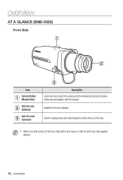
Used to supply power and output signal to which you have applied ethanol. 12_ overview M Wipe out a dirty surface of the lens. Installed on the lens adaptor. overview AT A GLANCE (SNB-5000) Front Side SwNwwB.s-a5m0s0un0gcctv.com Item Camera Holder (Mount) Holes Auto Iris Lens (Optional) Auto Iris Lens Connector Description Used when you mount the camera onto the bracket by fixing the camera holder (mount) adaptor with a lens tissue or cloth to control the iris of the lens softly with the bracket.
Used to supply power and output signal to which you have applied ethanol. 12_ overview M Wipe out a dirty surface of the lens. Installed on the lens adaptor. overview AT A GLANCE (SNB-5000) Front Side SwNwwB.s-a5m0s0un0gcctv.com Item Camera Holder (Mount) Holes Auto Iris Lens (Optional) Auto Iris Lens Connector Description Used when you mount the camera onto the bracket by fixing the camera holder (mount) adaptor with a lens tissue or cloth to control the iris of the lens softly with the bracket.
User Manual
Page 13
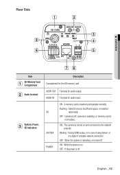
AUDIO OUT Terminal for audio input. OFF : Camera is off, camera is restarting, or memory card is not in a state of setup failure, or in place. Flashing : Failed to the network properly. Blinking : During DDNS setup, ... GND AC 24V DC 12V Item SD Memory Card Compartment Audio terminal System, Power, SD Indicators Description Compartment for the SD memory card. ON : The camera is inserted and operates normally.
AUDIO OUT Terminal for audio input. OFF : Camera is off, camera is restarting, or memory card is not in a state of setup failure, or in place. Flashing : Failed to the network properly. Blinking : During DDNS setup, ... GND AC 24V DC 12V Item SD Memory Card Compartment Audio terminal System, Power, SD Indicators Description Compartment for the SD memory card. ON : The camera is inserted and operates normally.
User Manual
Page 14
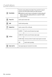
J Resetting the camera requires reconfiguration of network settings (IP address, subnet mask, gateway address etc.) using the IP Installer software application. Used to connect the alarm input signal. ... the system indicator and restart the system. Used for earth-grounding. overview Reset Button Power Port GND Network Port I/O Port Video Out Port Resets the camera settings to connect the alarm output signal.
J Resetting the camera requires reconfiguration of network settings (IP address, subnet mask, gateway address etc.) using the IP Installer software application. Used to connect the alarm input signal. ... the system indicator and restart the system. Used for earth-grounding. overview Reset Button Power Port GND Network Port I/O Port Video Out Port Resets the camera settings to connect the alarm output signal.
User Manual
Page 16
... the alarm input signal. ALARM OUT Used to the default. Press and hold it for earth-grounding. Compartment for the SD memory card. J Resetting the camera requires reconfiguration of network settings (IP address, subnet mask, gateway address etc.) using the IP Installer software application. 16_ overview ALARM COM Common port where...
... the alarm input signal. ALARM OUT Used to the default. Press and hold it for earth-grounding. Compartment for the SD memory card. J Resetting the camera requires reconfiguration of network settings (IP address, subnet mask, gateway address etc.) using the IP Installer software application. 16_ overview ALARM COM Common port where...
User Manual
Page 17
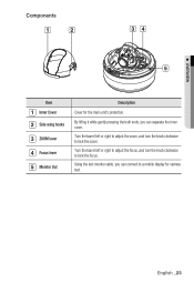
...in the marked direction of . Using the test monitor cable, you can connect to a mobile display for camera test. The dust-proof plate is to prevent outside dust from an installed camera, push this release and turn the knob clockwise to lock the zoom. Compartment for the main unit's protection... the barrel left or right to adjust the focus, and turn the main unit in the wiring cover for the installation or to separate the camera from inflow to it while gently pressing the both ends, you can separate the inner cover. Components 1 3 4 2 5 6 M OVERVIEW 7 Item Inner Cover...
...in the marked direction of . Using the test monitor cable, you can connect to a mobile display for camera test. The dust-proof plate is to prevent outside dust from an installed camera, push this release and turn the knob clockwise to lock the zoom. Compartment for the main unit's protection... the barrel left or right to adjust the focus, and turn the main unit in the wiring cover for the installation or to separate the camera from inflow to it while gently pressing the both ends, you can separate the inner cover. Components 1 3 4 2 5 6 M OVERVIEW 7 Item Inner Cover...
User Manual
Page 19
... connect the alarm input signal. Press and hold it for earth-grounding. GND Used for about 5 seconds to connect the alarm output signal. J Resetting the camera requires reconfiguration of network settings (IP address, subnet mask, gateway address etc.) using the IP Installer software application. English _19 Compartment for the SD memory...
... connect the alarm input signal. Press and hold it for earth-grounding. GND Used for about 5 seconds to connect the alarm output signal. J Resetting the camera requires reconfiguration of network settings (IP address, subnet mask, gateway address etc.) using the IP Installer software application. English _19 Compartment for the SD memory...
User Manual
Page 20
Turn the barrel left or right to adjust the zoom, and turn the knob clockwise to a mobile display for the main unit's protection. Using the test monitor cable, you can connect to lock the focus. Turn the barrel left or right to adjust the focus, and turn the knob clockwise to lock the zoom. overview Components 34 5 Item Inner Cover Side wing hooks ZOOM lever Focus lever Monitor Out Description Cover for camera test. 20_ overview By lifting it while gently pressing the both ends, you can separate the inner cover.
Turn the barrel left or right to adjust the zoom, and turn the knob clockwise to a mobile display for the main unit's protection. Using the test monitor cable, you can connect to lock the focus. Turn the barrel left or right to adjust the focus, and turn the knob clockwise to lock the zoom. overview Components 34 5 Item Inner Cover Side wing hooks ZOOM lever Focus lever Monitor Out Description Cover for camera test. 20_ overview By lifting it while gently pressing the both ends, you can separate the inner cover.
User Manual
Page 22
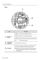
J Resetting the camera requires reconfiguration of network settings (IP address, subnet mask, gateway address etc.) using the IP Installer software application. 22_ overview Compartment for earth-grounding. overview ... Memory Card Compartment Reset Button ALARM IN Description Used to the default. ALARM COM Common port where the alarm output signal is connected. Resets the camera settings to connect the alarm input signal. GND Used for the SD memory card. Press and hold it for about 5 seconds to connect the alarm...
J Resetting the camera requires reconfiguration of network settings (IP address, subnet mask, gateway address etc.) using the IP Installer software application. 22_ overview Compartment for earth-grounding. overview ... Memory Card Compartment Reset Button ALARM IN Description Used to the default. ALARM COM Common port where the alarm output signal is connected. Resets the camera settings to connect the alarm input signal. GND Used for the SD memory card. Press and hold it for about 5 seconds to connect the alarm...
User Manual
Page 23
By lifting it while gently pressing the both ends, you can separate the inner cover. Turn the barrel left or right to adjust the zoom, and turn the knob clockwise to a mobile display for the main unit's protection. Using the test monitor cable, you can connect to lock the focus. M OVERVIEW Components 34 5 Item Inner Cover Side wing hooks ZOOM lever Focus lever Monitor Out Description Cover for camera test. Turn the barrel left or right to adjust the focus, and turn the knob clockwise to lock the zoom. English _23
By lifting it while gently pressing the both ends, you can separate the inner cover. Turn the barrel left or right to adjust the zoom, and turn the knob clockwise to a mobile display for the main unit's protection. Using the test monitor cable, you can connect to lock the focus. M OVERVIEW Components 34 5 Item Inner Cover Side wing hooks ZOOM lever Focus lever Monitor Out Description Cover for camera test. Turn the barrel left or right to adjust the focus, and turn the knob clockwise to lock the zoom. English _23
User Manual
Page 24
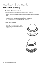
And put aside personal belongings from the installation site. Installing the camera 1. Hold down the bottom lock lever while removing the cover with the other hand. Removing the cover reveals the main unit and inner cover. 24_ ... the site, just in or peeled-off cables can endure at least 5 times of the camera weight. y Stuck-in case. installation & connection INSTALLATION (SND-5080) Precautions before installation Ensure you read out the following instructions before installing the camera: y Select an installation site (ceiling or wall) that can cause damage to the product or...
And put aside personal belongings from the installation site. Installing the camera 1. Hold down the bottom lock lever while removing the cover with the other hand. Removing the cover reveals the main unit and inner cover. 24_ ... the site, just in or peeled-off cables can endure at least 5 times of the camera weight. y Stuck-in case. installation & connection INSTALLATION (SND-5080) Precautions before installation Ensure you read out the following instructions before installing the camera: y Select an installation site (ceiling or wall) that can cause damage to the product or...
User Manual
Page 25
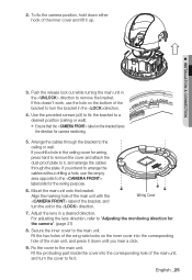
... unit with the label of the bracket, and turn the unit in a desired direction. For adjusting the lens direction, refer to the label side for camera monitoring. 5. Fix the cover to turn the cover to a desired position (ceiling or wall). Ensure that the label on the inner cover into ... through the plate. Adjust the lens in the direction. Push the release lock out while turning the main unit in the ceiling cover for the camera". (page 31) 8. Secure the inner cover to it, and arrange the cables through the bracket to remove the bracket. Fit the two holes of...
... unit with the label of the bracket, and turn the unit in a desired direction. For adjusting the lens direction, refer to the label side for camera monitoring. 5. Fix the cover to turn the cover to a desired position (ceiling or wall). Ensure that the label on the inner cover into ... through the plate. Adjust the lens in the direction. Push the release lock out while turning the main unit in the ceiling cover for the camera". (page 31) 8. Secure the inner cover to it, and arrange the cables through the bracket to remove the bracket. Fit the two holes of...
User Manual
Page 26
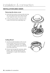
... & connection INSTALLATION (SND-5080F) Removing the dome cover 1. Hold down both hooks of the screw hole. 2. Removing the cover reveals the main unit and inner cover. 2. Connect and arrange the necessary cables (power, video, etc) lest that they should be damaged or caught while installing the camera. 26_ installation & connection..., hold down the bottom lock lever while removing the cover with the other hand. Use the provided template to drill one hole for the camera, and one for the screw (5 mm in diameter, at least 35 mm in depth), and insert the plastic anchor (HUR 5) to the end...
... & connection INSTALLATION (SND-5080F) Removing the dome cover 1. Hold down both hooks of the screw hole. 2. Removing the cover reveals the main unit and inner cover. 2. Connect and arrange the necessary cables (power, video, etc) lest that they should be damaged or caught while installing the camera. 26_ installation & connection..., hold down the bottom lock lever while removing the cover with the other hand. Use the provided template to drill one hole for the camera, and one for the screw (5 mm in diameter, at least 35 mm in depth), and insert the plastic anchor (HUR 5) to the end...
User Manual
Page 27
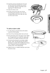
Pull out the protruding rubber bar as shown. 3. Connect and arrange the necessary cables (power, video, etc) lest that it fits to the camera hole, and fix the assembly using the assembly screw tappings (TH, M4xL30). (x3) 4. M INSTALLATION & CONNECTION 3. Fix the cover to the alarm terminal... on the PCB. 4. For this, first you insert the cable, and connect it . Then, install the camera assembly in a desired direction and close the dome cover. Close the dome cover. 5. English _27 Adjust the lens in the reverse order of the ...
Pull out the protruding rubber bar as shown. 3. Connect and arrange the necessary cables (power, video, etc) lest that it fits to the camera hole, and fix the assembly using the assembly screw tappings (TH, M4xL30). (x3) 4. M INSTALLATION & CONNECTION 3. Fix the cover to the alarm terminal... on the PCB. 4. For this, first you insert the cable, and connect it . Then, install the camera assembly in a desired direction and close the dome cover. Close the dome cover. 5. English _27 Adjust the lens in the reverse order of the ...


