Service Manual
Page 1
Array course control 5. Block Diagrams 8. Specification 3. GSM TELEPHONE SGH-T429 UMTS TELEPHONE CONTENTS 1. Safety Precautions 2. Flow Chart of Troubleshooting 10. Reference data Product Function 4. PCB Diagrams 9. MAIN Electrical Parts List 7. Exploded View/Disassembly and Assembly Instructions 6.
Array course control 5. Block Diagrams 8. Specification 3. GSM TELEPHONE SGH-T429 UMTS TELEPHONE CONTENTS 1. Safety Precautions 2. Flow Chart of Troubleshooting 10. Reference data Product Function 4. PCB Diagrams 9. MAIN Electrical Parts List 7. Exploded View/Disassembly and Assembly Instructions 6.
Service Manual
Page 3
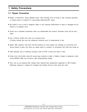
... overcurrent and furious flames of connecting Test Pack and tuning on SEC System. z Don't use as you disassemble this rules. 1-1 SAMSUNG Proprietary-Contents may change other material than replacement registered on . 1. Safety Precautions 1-1. z Repair after disassembling charger. Otherwise engineer in condition of parts etc) when you repair board in charge isn't charged with...
... overcurrent and furious flames of connecting Test Pack and tuning on SEC System. z Don't use as you disassemble this rules. 1-1 SAMSUNG Proprietary-Contents may change other material than replacement registered on . 1. Safety Precautions 1-1. z Repair after disassembling charger. Otherwise engineer in condition of parts etc) when you repair board in charge isn't charged with...
Service Manual
Page 13
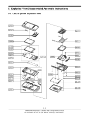
Exploded View/Disassembly&Assembly Instructions 5-1. Cellular phone Exploded View QFU01 QCA01 QKP02 QMW01 QLC02 QLC01 QSP01 QMO01 QMP02 QPC01 QFL01 QCR17 QCW01 QCA05 QCK01 QVO01 QME02 QMP01 QFL02 QHI01 QFR01 QIF01 QCR06 QKP01 QME01 QBR01 QMI03 QMI01 QAN02 QRE01 QRF01 QCR06 QSC13 QBA01 QBA00 5-3 SAMSUNG Proprietary-Contents may change without notice This Document can not be used without Samsung's authorization 5.
Exploded View/Disassembly&Assembly Instructions 5-1. Cellular phone Exploded View QFU01 QCA01 QKP02 QMW01 QLC02 QLC01 QSP01 QMO01 QMP02 QPC01 QFL01 QCR17 QCW01 QCA05 QCK01 QVO01 QME02 QMP01 QFL02 QHI01 QFR01 QIF01 QCR06 QKP01 QME01 QBR01 QMI03 QMI01 QAN02 QRE01 QRF01 QCR06 QSC13 QBA01 QBA00 5-3 SAMSUNG Proprietary-Contents may change without notice This Document can not be used without Samsung's authorization 5.
Service Manual
Page 14
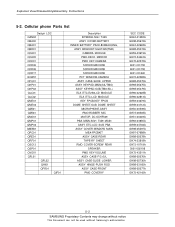
Exploded View/Disassembly&Assembly Instructions 5-2. Cellular phone Parts list Design LOC QAN02 QBA00 QBA01 QBR01 QCA01 QCA05 QCK01 QCR06 QCR06 QCR17 QCW01 QFU01 QKP01 QKP02 QLC01 QLC02 QME01 QME02 QMI01 QMI03 QMO01 QMP01 QMP02 QMW01 QPC01 QRE01 QRF01 QSC13 QSP01 QVO01 QFL01 QFL02 QHI01 QFR01 QIF01 Description INTENNA-SGH T429 ASSY COVER-BATTERY ...
Exploded View/Disassembly&Assembly Instructions 5-2. Cellular phone Parts list Design LOC QAN02 QBA00 QBA01 QBR01 QCA01 QCA05 QCK01 QCR06 QCR06 QCR17 QCW01 QFU01 QKP01 QKP02 QLC01 QLC02 QME01 QME02 QMI01 QMI03 QMO01 QMP01 QMP02 QMW01 QPC01 QRE01 QRF01 QSC13 QSP01 QVO01 QFL01 QFL02 QHI01 QFR01 QIF01 Description INTENNA-SGH T429 ASSY COVER-BATTERY ...
Service Manual
Page 15
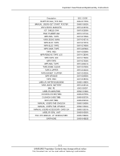
Exploded View/Disassembly&Assembly Instructions Description ADAPTOR-SGH_T419 BLK MANUAL USERS-GET START POSTER VINYL-BOHO MAIN(STA) ICT SHIELD-CAN RMO RUBBER-SIM MPR-INSU TAPE VINYL-...-14285A GH74-34914A 6902-000297 GH68-15188A GH69-02793A GH69-05572A GH69-05616A GH68-15499A GH68-15500A GH68-15501A GH68-04256A GH99-19962A GH59-04682B 5-3 SAMSUNG Proprietary-Contents may change without notice This Document can not be used without...
Exploded View/Disassembly&Assembly Instructions Description ADAPTOR-SGH_T419 BLK MANUAL USERS-GET START POSTER VINYL-BOHO MAIN(STA) ICT SHIELD-CAN RMO RUBBER-SIM MPR-INSU TAPE VINYL-...-14285A GH74-34914A 6902-000297 GH68-15188A GH69-02793A GH69-05572A GH69-05616A GH68-15499A GH68-15500A GH68-15501A GH68-04256A GH99-19962A GH59-04682B 5-3 SAMSUNG Proprietary-Contents may change without notice This Document can not be used without...

Service Manual
Page 16
... Instructions 5-3. Remove the RF Sheet. Disassembly - Disassembly 1. Disassembly - SHIELDCAN & KEYPAD Remove CAMERA KEY and VOLUME KEY and remove SIDE DOME SHEET. Lift up Ma in P B A to separate LCD FPCB. 3. Unscrew the 6 points. Main ... from the front cover by using the tweezer. 2. Separate the rear cover from Main PBA. Remove SHIELD CAN and KEYPAD carefully. Disassembly - Hold up the bottom of FRONT COVER ands separate the SHIELD CAN and fix FRONT RIB. 5-4 SAMSUNG Proprietary-Contents may change without notice This Document can not be used without...
... Instructions 5-3. Remove the RF Sheet. Disassembly - Disassembly 1. Disassembly - SHIELDCAN & KEYPAD Remove CAMERA KEY and VOLUME KEY and remove SIDE DOME SHEET. Lift up Ma in P B A to separate LCD FPCB. 3. Unscrew the 6 points. Main ... from the front cover by using the tweezer. 2. Separate the rear cover from Main PBA. Remove SHIELD CAN and KEYPAD carefully. Disassembly - Hold up the bottom of FRONT COVER ands separate the SHIELD CAN and fix FRONT RIB. 5-4 SAMSUNG Proprietary-Contents may change without notice This Document can not be used without...
Service Manual
Page 17
...on LCD EDGE and UPPER. 2. Separate SUB KEY PAD from UPPER carefully. 2. Disassemble UPPER and LOWER. Remove soldering tape and remove green tape. Separate LCD ASS'Y from FRONT COVER. Disassembly - Make LOWER hole and FRONT hole the same hole position and remove ConToCon ...FPCB. Separate CAMERA and ConToCon FPCB. 5-5 SAMSUNG Proprietary-Contents may change without notice This Document can not be used without Samsung's authorization 4. Separate CAMERA, ...
...on LCD EDGE and UPPER. 2. Separate SUB KEY PAD from UPPER carefully. 2. Disassemble UPPER and LOWER. Remove soldering tape and remove green tape. Separate LCD ASS'Y from FRONT COVER. Disassembly - Make LOWER hole and FRONT hole the same hole position and remove ConToCon ...FPCB. Separate CAMERA and ConToCon FPCB. 5-5 SAMSUNG Proprietary-Contents may change without notice This Document can not be used without Samsung's authorization 4. Separate CAMERA, ...
Service Manual
Page 18
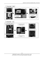
... same hole position and insert ConToCon FPCB into CONNECTOR and Lock it 4. Screw the 4 points. 5-6 SAMSUNG Proprietary-Contents may change without notice This Document can not be used without Samsung's authorization LCD 1. Attach LCD ASS'Y to fix double stick tape. 2. Exploded View/Disassembly&Assembly Instructions 5-3-2. Assembly - Assembly 1. Insert CAMERA module into the hole. 2.
... same hole position and insert ConToCon FPCB into CONNECTOR and Lock it 4. Screw the 4 points. 5-6 SAMSUNG Proprietary-Contents may change without notice This Document can not be used without Samsung's authorization LCD 1. Attach LCD ASS'Y to fix double stick tape. 2. Exploded View/Disassembly&Assembly Instructions 5-3-2. Assembly - Assembly 1. Insert CAMERA module into the hole. 2.
Service Manual
Page 19
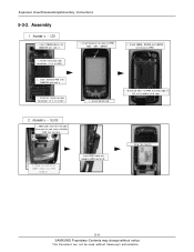
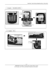
Insert CAMERA KEY and VOLUME KEY 1. Assembly - Slide up and put in PBA Attach KEY FPCB to KEYPAD. 4. Attach SHIELD CAN to PBA CONNECTOR. 5-7 SAMSUNG Proprietary-Contents may change without notice This Document can not be used without Samsung's authorization Exploded View/Disassembly&Assembly Instructions 3.Assembly - SHIELDCAN & KEYPAD Attach KEYPAD to LCD FPCB. PBA Connect PBA CONNECTOR to FRONT RIB. 2. Attach SIDE KEY and DOME SHEET along the lead gutter.
Insert CAMERA KEY and VOLUME KEY 1. Assembly - Slide up and put in PBA Attach KEY FPCB to KEYPAD. 4. Attach SHIELD CAN to PBA CONNECTOR. 5-7 SAMSUNG Proprietary-Contents may change without notice This Document can not be used without Samsung's authorization Exploded View/Disassembly&Assembly Instructions 3.Assembly - SHIELDCAN & KEYPAD Attach KEYPAD to LCD FPCB. PBA Connect PBA CONNECTOR to FRONT RIB. 2. Attach SIDE KEY and DOME SHEET along the lead gutter.
Service Manual
Page 20
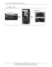
Attach RF Sheet here. 5-8 SAMSUNG Proprietary-Contents may change without notice This Document can not be used without Samsung's authorization Assembly - Fix REAR SCREW CAPS 2. REAR Attach REAR COVER to the body and assemble them Screw the 6 points. 1. Exploded View/Disassembly&Assembly Instructions 5. Attach REAR SCREW CAPS Here. 2.
Attach RF Sheet here. 5-8 SAMSUNG Proprietary-Contents may change without notice This Document can not be used without Samsung's authorization Assembly - Fix REAR SCREW CAPS 2. REAR Attach REAR COVER to the body and assemble them Screw the 6 points. 1. Exploded View/Disassembly&Assembly Instructions 5. Attach REAR SCREW CAPS Here. 2.


