
User Manual
Page 2
.... Playing a DVD or a game console may shorten the lifetime of the product. © 2006 Samsung Electronics Co., Ltd. Installing the product in height, so do so may be prevented from Video games and PC for longer than 2 hours as it operates for 24 hours such as the airport, the train station or etc. User Instructions ◆ Screen Image retention Do not display...
.... Playing a DVD or a game console may shorten the lifetime of the product. © 2006 Samsung Electronics Co., Ltd. Installing the product in height, so do so may be prevented from Video games and PC for longer than 2 hours as it operates for 24 hours such as the airport, the train station or etc. User Instructions ◆ Screen Image retention Do not display...

User Manual
Page 4
... Remote Control 9 ■ Assembling the Stand-Base 9 ■ Installing the Display on the Wall Attachment Panel 10 ■ Installing the Display Vertically 12 ■ Before Using the Video Wall and the Multiple Display Control function ........ 12 ■ Connecting Speakers 13 ■ Switching Your PDP Display On and Off 15 ■ Choosing Your Language 15 ◆ USING YOUR DISPLAY ■ Changing the Picture Standard 16 ■ Customizing the Picture Settings 17 ■ Adjusting the RGB Color (PC Mode 18 ■ Setting the Picture...
... Remote Control 9 ■ Assembling the Stand-Base 9 ■ Installing the Display on the Wall Attachment Panel 10 ■ Installing the Display Vertically 12 ■ Before Using the Video Wall and the Multiple Display Control function ........ 12 ■ Connecting Speakers 13 ■ Switching Your PDP Display On and Off 15 ■ Choosing Your Language 15 ◆ USING YOUR DISPLAY ■ Changing the Picture Standard 16 ■ Customizing the Picture Settings 17 ■ Adjusting the RGB Color (PC Mode 18 ■ Setting the Picture...
User Manual
Page 5
... Screen 32 ■ Displaying the Setting Information 33 ■ Setting and Displaying the Current Time 33 ■ Switching the PDP Display On and Off Automatically 34 ■ Selecting the Fan 36 ■ Viewing the Picture in Picture (PIP 37 ■ Viewing an External Signal Source 38 ◆ ADDITIONAL INFORMATION AND CONNECTIONS ■ Connecting to the Audio/Video Input 39 ■ Connecting to the S-Video Input 40 ■ Connecting to the Component Input 40 ■ Connecting to the DVD/DTV Receiver Input...
... Screen 32 ■ Displaying the Setting Information 33 ■ Setting and Displaying the Current Time 33 ■ Switching the PDP Display On and Off Automatically 34 ■ Selecting the Fan 36 ■ Viewing the Picture in Picture (PIP 37 ■ Viewing an External Signal Source 38 ◆ ADDITIONAL INFORMATION AND CONNECTIONS ■ Connecting to the Audio/Video Input 39 ■ Connecting to the S-Video Input 40 ■ Connecting to the Component Input 40 ■ Connecting to the DVD/DTV Receiver Input...

User Manual
Page 6
... standby mode depending on the model. ◆ The VOL -, + and SEL , buttons have the same function as the buttons on the remote control. ◆ If the remote control no longer works or you can use the SEL , buttons to turn the PDP Display on and off. Black - Power On; Control Panel ➢ The actual configuration of your PDP Display may be different, depending on your settings in the menu. Select the external input source. - MENU Display the on-screen menu. - Adjust...
... standby mode depending on the model. ◆ The VOL -, + and SEL , buttons have the same function as the buttons on the remote control. ◆ If the remote control no longer works or you can use the SEL , buttons to turn the PDP Display on and off. Black - Power On; Control Panel ➢ The actual configuration of your PDP Display may be different, depending on your settings in the menu. Select the external input source. - MENU Display the on-screen menu. - Adjust...

User Manual
Page 7
... : Outputs for RGB HV video signal input from the PC. ➢ "PC Mode" from this page onward means PC1/PC2 mode using RGB1(PC1) and RGB2(PC2). PC OUT1 : Connect to the audio output jack on external devices. e) PC IN1/PC OUT1 - Rear Panel PPM42M6S/42M6H/50M6H PPM63M6H a) POWER IN Connect the supplied power cord. b) EXT SPEAKER (8Ω) Connect external speakers. h) COMPONENT IN Video (Y/PB/PR) and audio (L/R) inputs for the MDC function when connecting with your PDP Display...
... : Outputs for RGB HV video signal input from the PC. ➢ "PC Mode" from this page onward means PC1/PC2 mode using RGB1(PC1) and RGB2(PC2). PC OUT1 : Connect to the audio output jack on external devices. e) PC IN1/PC OUT1 - Rear Panel PPM42M6S/42M6H/50M6H PPM63M6H a) POWER IN Connect the supplied power cord. b) EXT SPEAKER (8Ω) Connect external speakers. h) COMPONENT IN Video (Y/PB/PR) and audio (L/R) inputs for the MDC function when connecting with your PDP Display...

User Manual
Page 8
... SOUND SWITCH-OFF VOLUME DECREASE SETTING THE TIMER MENU DISPLAY MOVE TO THE REQUIRED MENU OPTION/ ADJUST AN OPTION VALUE RESPECTIVELY PICTURE EFFECT SELECTION AUTO ADJUSTMENT IN PC MODE PIP FUNCTIONS: - English - 8 SOURCE SELECTION (SOURCE) PDP DISPLAY OFF PICTURE STILL NEXT CHANNEL EXTERNAL INPUT SELECTION PREVIOUS CHANNEL INFORMATION DISPLAY EXIT FROM ANY DISPLAY CONFIRM YOUR CHOICE (STORE OR ENTER) SOUND EFFECT SELECTION PICTURE SIZE MULTIPLE DISPLAY CONTROL SCREEN EFFECT SELECTION (BURNING PROTECTION) ➢ The performance of the remote control may be affected by bright light...
... SOUND SWITCH-OFF VOLUME DECREASE SETTING THE TIMER MENU DISPLAY MOVE TO THE REQUIRED MENU OPTION/ ADJUST AN OPTION VALUE RESPECTIVELY PICTURE EFFECT SELECTION AUTO ADJUSTMENT IN PC MODE PIP FUNCTIONS: - English - 8 SOURCE SELECTION (SOURCE) PDP DISPLAY OFF PICTURE STILL NEXT CHANNEL EXTERNAL INPUT SELECTION PREVIOUS CHANNEL INFORMATION DISPLAY EXIT FROM ANY DISPLAY CONFIRM YOUR CHOICE (STORE OR ENTER) SOUND EFFECT SELECTION PICTURE SIZE MULTIPLE DISPLAY CONTROL SCREEN EFFECT SELECTION (BURNING PROTECTION) ➢ The performance of the remote control may be affected by bright light...

User Manual
Page 11
...°. English - 11 holders into the plastic hanger. (See the figure below) ☛ ◆ Mount the product on the wall bracket and make sure it is firmly fixed to the bracket. PDP Display Wall Bracket Angle Adjustment ➢ Adjust the bracket angle to -2o before installing it is properly fixed to the left or the right side of the product. Make sure to reinsert...
...°. English - 11 holders into the plastic hanger. (See the figure below) ☛ ◆ Mount the product on the wall bracket and make sure it is firmly fixed to the bracket. PDP Display Wall Bracket Angle Adjustment ➢ Adjust the bracket angle to -2o before installing it is properly fixed to the left or the right side of the product. Make sure to reinsert...

User Manual
Page 12
... the remote control only for the model PPM42M6S is not available. Example for PDP Display adjustment. If you have to "Setting the Multiple Screen" on the left when viewed from the figure below. ➢ The Fan function for the PDP Display that are installed close together. Example for 2x2 Video Wall function Rear of the PDP Display Example for 2x2 Video Wall connections Rear of the PDP Display with menu buttons on page 32. Before Using the Video Wall...
... the remote control only for the model PPM42M6S is not available. Example for PDP Display adjustment. If you have to "Setting the Multiple Screen" on the left when viewed from the figure below. ➢ The Fan function for the PDP Display that are installed close together. Example for 2x2 Video Wall function Rear of the PDP Display Example for 2x2 Video Wall connections Rear of the PDP Display with menu buttons on page 32. Before Using the Video Wall...

User Manual
Page 19
... œ or √ button until you reach the optimal setting. ➢ Press the ... Image Reset is displayed. The settings are automatically reset. Image Lock Coarse 50 Fine 30 Move Enter Return Coarse 50 Position Move Enter Return Auto Adjustment in Progress Please wait. Result: The previously adjusted settings will automatically return to the previous picture. 13 To return the factory defaults, select Image Reset by pressing the or...
... œ or √ button until you reach the optimal setting. ➢ Press the ... Image Reset is displayed. The settings are automatically reset. Image Lock Coarse 50 Fine 30 Move Enter Return Coarse 50 Position Move Enter Return Auto Adjustment in Progress Please wait. Result: The previously adjusted settings will automatically return to the previous picture. 13 To return the factory defaults, select Image Reset by pressing the or...

User Manual
Page 25
... panel lock setting, so keep the remote control away from unauthorized users. 1 Press the MENU ( ) button. Only remote control can , however, still be operated via the remote control. Result: The main menu is displayed. 3 Press the ENTER ( ) button. 4 Press the ▲ or ▼ button to select Safety Lock. Function Screen Burn Protection Safety Lock Multi Control Video Wall Fan : Off Move Enter Return Safety Lock Key Lock IR Lock Change PIN : Off Move Enter Return Safety Lock Key Lock...
... panel lock setting, so keep the remote control away from unauthorized users. 1 Press the MENU ( ) button. Only remote control can , however, still be operated via the remote control. Result: The main menu is displayed. 3 Press the ENTER ( ) button. 4 Press the ▲ or ▼ button to select Safety Lock. Function Screen Burn Protection Safety Lock Multi Control Video Wall Fan : Off Move Enter Return Safety Lock Key Lock IR Lock Change PIN : Off Move Enter Return Safety Lock Key Lock...

User Manual
Page 28
... Control ID Setup ID Input : 00 : -- Result: The Multi Control menu is switched to the Menu screen and you to easily control the connected PDP Displays on the remote control. ➢ Refer to connected PDP Displays. 1 Press the MENU ( ) button. When entering the ID Input number of PDP1 while the PDP Display is set in the ID Input mode, only PDP1 is displayed with the remote control and displays the standby mode of ID Input. ➢ For further details, refer to the MDC program guide...
... Control ID Setup ID Input : 00 : -- Result: The Multi Control menu is switched to the Menu screen and you to easily control the connected PDP Displays on the remote control. ➢ Refer to connected PDP Displays. 1 Press the MENU ( ) button. When entering the ID Input number of PDP1 while the PDP Display is set in the ID Input mode, only PDP1 is displayed with the remote control and displays the standby mode of ID Input. ➢ For further details, refer to the MDC program guide...

User Manual
Page 32
... PDP Display. Press the ENTER ( ) button. 10 Select the option (2x2, 3x3, 4x4, 5x1, or 1x5) by pressing the ▲ or ▼ button. Press the ENTER ( ) button. 11 Press the œ or √ button to exit. ➢ ◆ The PIP function and Picture Size do not work during the Video Wall operation. ◆ The VESA Format input does not support the Video Wall function in DVI mode. Setting the Multiple Screen Function Screen Burn...
... PDP Display. Press the ENTER ( ) button. 10 Select the option (2x2, 3x3, 4x4, 5x1, or 1x5) by pressing the ▲ or ▼ button. Press the ENTER ( ) button. 11 Press the œ or √ button to exit. ➢ ◆ The PIP function and Picture Size do not work during the Video Wall operation. ◆ The VESA Format input does not support the Video Wall function in DVI mode. Setting the Multiple Screen Function Screen Burn...

User Manual
Page 37
...DVI X X X X X X X X X X X X X X X X X X X X X X X X Picture Mode : Dynamic Color Control Size : 16:9 PIP Move Enter Return PIP Source Position PIP : Off Off : AV On : Move Enter Return PIP Source Position PIP : On : AV AV : S-Video Move Enter Return PIP Source Position PIP : On : AV : Move Enter Return English - 37 Viewing the Picture in Picture (PIP) You can PDP Display the video input from any connected devices while monitoring other video inputs. 1 Press the MENU ( ) button. To activate, set PIP to assign a source of the remote control...
...DVI X X X X X X X X X X X X X X X X X X X X X X X X Picture Mode : Dynamic Color Control Size : 16:9 PIP Move Enter Return PIP Source Position PIP : Off Off : AV On : Move Enter Return PIP Source Position PIP : On : AV AV : S-Video Move Enter Return PIP Source Position PIP : On : AV : Move Enter Return English - 37 Viewing the Picture in Picture (PIP) You can PDP Display the video input from any connected devices while monitoring other video inputs. 1 Press the MENU ( ) button. To activate, set PIP to assign a source of the remote control...

User Manual
Page 39
... are switched off. Refer to the documentation supplied with an Composite Video output, such as a camcorder or VCR. Rear of the PDP Display (Input) VCR ① DVD Decoder / Video game device The "AV OUT" connectors are used for the equipment with your PDP Display, ensure that you can redirect the signal from "AV IN" to "AV OUT". ② When you wish to record a programme, connect the receiver...
... are switched off. Refer to the documentation supplied with an Composite Video output, such as a camcorder or VCR. Rear of the PDP Display (Input) VCR ① DVD Decoder / Video game device The "AV OUT" connectors are used for the equipment with your PDP Display, ensure that you can redirect the signal from "AV IN" to "AV OUT". ② When you wish to record a programme, connect the receiver...

User Manual
Page 40
Connecting to the Component Input Rear of the PDP Display Camcorder ① and VCR ① To play picture and sound, both the S-VIDEO and RCA connectors must be used. Connecting to the S-Video Input The S-VIDEO and RCA (AUDIO-L/R) connectors are used for DTV receiver or DVD. (480i,p/576i,p/720p/1080i) DTV Receiver English - 40 Rear of the PDP Display DVD The COMPONENT IN connectors are used for equipment with an S-Video output, such as a camcorder or VCR.
Connecting to the Component Input Rear of the PDP Display Camcorder ① and VCR ① To play picture and sound, both the S-VIDEO and RCA connectors must be used. Connecting to the S-Video Input The S-VIDEO and RCA (AUDIO-L/R) connectors are used for DTV receiver or DVD. (480i,p/576i,p/720p/1080i) DTV Receiver English - 40 Rear of the PDP Display DVD The COMPONENT IN connectors are used for equipment with an S-Video output, such as a camcorder or VCR.

User Manual
Page 41
Connecting to the DVI Input The "DVI IN" (video) and "AUDIO" connectors are used for equipment with a DVD/ DTV Receiver output. (480i, 576i, 480p, 576p, 720p, 1080i) DVD Digital Set-Top Box Connecting to the DVD/DTV Receiver Input Rear of the PDP Display and Personal Computer English - 41 Rear of the PDP Display Y / PB / PR L / R The "COMPONENT IN" (or "Y/PB/PR" (video) and "AUDIO") connectors are used for equipment with a DVI output.
Connecting to the DVI Input The "DVI IN" (video) and "AUDIO" connectors are used for equipment with a DVD/ DTV Receiver output. (480i, 576i, 480p, 576p, 720p, 1080i) DVD Digital Set-Top Box Connecting to the DVD/DTV Receiver Input Rear of the PDP Display and Personal Computer English - 41 Rear of the PDP Display Y / PB / PR L / R The "COMPONENT IN" (or "Y/PB/PR" (video) and "AUDIO") connectors are used for equipment with a DVI output.

User Manual
Page 43
... reference to the Display Modes Table. The Display Properties will be different, depending upon your particular video card. English - 43 A new settings dialog box will be displayed. Otherwise, the message Out of Windows and your particular version of input range will be displayed. 2 Click on the Monitor tab, then set -up Your PC Software (Windows only) The Windows display-settings for a typical computer are supported by the PDP Display.
... reference to the Display Modes Table. The Display Properties will be different, depending upon your particular video card. English - 43 A new settings dialog box will be displayed. Otherwise, the message Out of Windows and your particular version of input range will be displayed. 2 Click on the Monitor tab, then set -up Your PC Software (Windows only) The Windows display-settings for a typical computer are supported by the PDP Display.

User Manual
Page 45
... time. This power management system saves energy by switching your PDP Display OFF when it is inactive and the vertical sync active, this feature. State Horizontal Sync Vertical Sync Video Power Indicator Normal Operation Active Active Active Green On Power-saving Function Mode Suspend Mode Position A1 Active Power-off Mode Position A2 Inactive Inactive Inactive Blanked Blanked Green Blinking Green Blinking (3 sec Interval) (3 sec Interval) ◆ If the horizontal sync is not needed...
... time. This power management system saves energy by switching your PDP Display OFF when it is inactive and the vertical sync active, this feature. State Horizontal Sync Vertical Sync Video Power Indicator Normal Operation Active Active Active Green On Power-saving Function Mode Suspend Mode Position A1 Active Power-off Mode Position A2 Inactive Inactive Inactive Blanked Blanked Green Blinking Green Blinking (3 sec Interval) (3 sec Interval) ◆ If the horizontal sync is not needed...
User Manual
Page 46
...: Power, Signal Cable. No sound or picture Normal picture but no sound No picture or black and white picture Sound and picture interference Remote control malfunctions Screen is black and power indicator light blinks steadily. ◆ Check that the mains lead has been connected to a wall socket. ◆ Check that you cannot solve the problem using its power management system. Move the computer's mouse or press any key on the remote control has been pressed. ◆ Adjust the color settings...
...: Power, Signal Cable. No sound or picture Normal picture but no sound No picture or black and white picture Sound and picture interference Remote control malfunctions Screen is black and power indicator light blinks steadily. ◆ Check that the mains lead has been connected to a wall socket. ◆ Check that you cannot solve the problem using its power management system. Move the computer's mouse or press any key on the remote control has been pressed. ◆ Adjust the color settings...
Brochure
Page 2
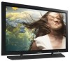
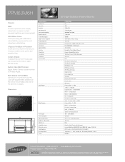
...-232C - 1 x 9-pin D-Sub Audio - 1 x RCA (L/R) Speaker - Longer Lifespan A display that is a registered mark of Colors Supported Viewing Angle (H/V) Scanning Frequency Color System Digital Comb Filter Color Tone Picture Mode Screen Mode Sound Effect Special Features Input Terminals 59.2" 35.2" Output Terminals 11.8" Power Supply Power Consumption 59.2" Dimension (W x H x D) Weight (set, without stand) Cabinet Color Included Accessories Optional Accessories Safety/Regulation Operating Condition Lifetime 35.2" 4.2" 11.8" 63" High-Definition Plasma Monitor PPM63M6H 63" 16:9 1366 x 768...
...-232C - 1 x 9-pin D-Sub Audio - 1 x RCA (L/R) Speaker - Longer Lifespan A display that is a registered mark of Colors Supported Viewing Angle (H/V) Scanning Frequency Color System Digital Comb Filter Color Tone Picture Mode Screen Mode Sound Effect Special Features Input Terminals 59.2" 35.2" Output Terminals 11.8" Power Supply Power Consumption 59.2" Dimension (W x H x D) Weight (set, without stand) Cabinet Color Included Accessories Optional Accessories Safety/Regulation Operating Condition Lifetime 35.2" 4.2" 11.8" 63" High-Definition Plasma Monitor PPM63M6H 63" 16:9 1366 x 768...


