
Service Manual
Page 1
Alignment and Adjustments 2. Block Diagrams 5. Wiring Diagram 6. Exploded Views and Parts List 3. Electrical Parts List 4. Schematic Diagrams - MICRO COMPONENT SYSTEM MM-ZJ6 SERVICE Manual MICRO COMPONENT SYSTEM CONTENTS 1. Confidential -
Alignment and Adjustments 2. Block Diagrams 5. Wiring Diagram 6. Exploded Views and Parts List 3. Electrical Parts List 4. Schematic Diagrams - MICRO COMPONENT SYSTEM MM-ZJ6 SERVICE Manual MICRO COMPONENT SYSTEM CONTENTS 1. Confidential -

Service Manual
Page 2
FEB. 2004 Printed in Korea Code no. AH68-01383X ELECTRONICS © Samsung Electronics Co.,Ltd.
FEB. 2004 Printed in Korea Code no. AH68-01383X ELECTRONICS © Samsung Electronics Co.,Ltd.
Service Manual
Page 3
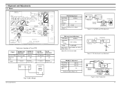
... Distortion (0.4% below) (Figure 1-1) Output GND FM S.S.G FM Antenna SET Terminal Input Oscilloscope Speaker Terminal output Input Distortion Meter Figure1-1 IF CENTER and THD Adjustment FM Search Level Adjustment SSG FREQ. 98 MHz Adjustment point (SVR1) Output SVR1 (10KΩ) 28 dB(±2dB) Adjust SVR1 so that "TUNED" of Tuner PCB ITEAM AM(MW) OSC Adjustment Received FREQ. Tuner * Adjustment Location of LCD is lighted (Figure 1-2) *Adjust FM S.S.G level to 28dB 28 dB...
... Distortion (0.4% below) (Figure 1-1) Output GND FM S.S.G FM Antenna SET Terminal Input Oscilloscope Speaker Terminal output Input Distortion Meter Figure1-1 IF CENTER and THD Adjustment FM Search Level Adjustment SSG FREQ. 98 MHz Adjustment point (SVR1) Output SVR1 (10KΩ) 28 dB(±2dB) Adjust SVR1 so that "TUNED" of Tuner PCB ITEAM AM(MW) OSC Adjustment Received FREQ. Tuner * Adjustment Location of LCD is lighted (Figure 1-2) *Adjust FM S.S.G level to 28dB 28 dB...
Service Manual
Page 4
... with REGION LOCK. Adjust Deck 1 Play Level Step Item Pre-Setup Condition Pre-Setup After putting MTT- Standard Remark Max output and same phase (both channels) After adjustment secure it with REGION LOCK. 2. Turn the control screw to as in Figure 1-6. Press FWD PLAY connected to the frequency counter) Pre-Setup 1) Deck :MTT-111 2) Press PLAY SW button To Adjust Fixed Standard Remark 3KHz ±1% range Recording /Play head AZIMUTH control screw (RVS Play) AZIMUTH control...
... with REGION LOCK. Adjust Deck 1 Play Level Step Item Pre-Setup Condition Pre-Setup After putting MTT- Standard Remark Max output and same phase (both channels) After adjustment secure it with REGION LOCK. 2. Turn the control screw to as in Figure 1-6. Press FWD PLAY connected to the frequency counter) Pre-Setup 1) Deck :MTT-111 2) Press PLAY SW button To Adjust Fixed Standard Remark 3KHz ±1% range Recording /Play head AZIMUTH control screw (RVS Play) AZIMUTH control...
Service Manual
Page 5
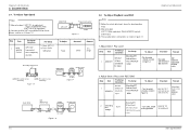
BLK Specification CMAL1Z230A HADKH5655A MAIN BELT FF19S-31 F765-292 F514-129 CCM09-120L2-6 SG-107F3;KODENSHI SPLFF SPLFE1 Remarks A/STOP F513-853 FF19S-31 F765-292 F514-129 Samsung Electronics No. WHITE LEAF S/W - Code No. F513-853 FF19S-31 F765-292 F514-129 F514... PINCH BLK R ROLLER PINCH BLK L MOTOR REEL SENSOR LEAF S/W - BLK Specification CMAL1Z230A HADKH5655A MAIN BELT FF19S-31 F765-292 F514-129 F514-130 CCM09-120L2-6 SG-107F3;KODENSHI SPLFF SPLFE1 Remarks A/REV. Code No. WHITE LEAF S/W - 2.Exploded Views and Parts List 2-1 Cassette Deck (OPTION) 7 9 10 8 2 3 4 5 ...
BLK Specification CMAL1Z230A HADKH5655A MAIN BELT FF19S-31 F765-292 F514-129 CCM09-120L2-6 SG-107F3;KODENSHI SPLFF SPLFE1 Remarks A/STOP F513-853 FF19S-31 F765-292 F514-129 Samsung Electronics No. WHITE LEAF S/W - Code No. F513-853 FF19S-31 F765-292 F514-129 F514... PINCH BLK R ROLLER PINCH BLK L MOTOR REEL SENSOR LEAF S/W - BLK Specification CMAL1Z230A HADKH5655A MAIN BELT FF19S-31 F765-292 F514-129 F514-130 CCM09-120L2-6 SG-107F3;KODENSHI SPLFF SPLFE1 Remarks A/REV. Code No. WHITE LEAF S/W - 2.Exploded Views and Parts List 2-1 Cassette Deck (OPTION) 7 9 10 8 2 3 4 5 ...
Service Manual
Page 6
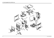
2-2 Total Exploded View and Parts List 2-2 Samsung Electronics
2-2 Total Exploded View and Parts List 2-2 Samsung Electronics
Service Manual
Page 7
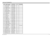
* Parts List of The Exploded View Samsung Electronics 2-3
* Parts List of The Exploded View Samsung Electronics 2-3
Service Manual
Page 8
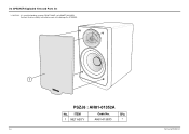
So when the disassembly, take extreme care not to CABINET WOODEN. 2-3 SPEAKER Exploded View and Parts list * CAUTION : It is used the bonding, connect FRONT PANEL to damage the SPEAKER. 2-4 Samsung Electronics
So when the disassembly, take extreme care not to CABINET WOODEN. 2-3 SPEAKER Exploded View and Parts list * CAUTION : It is used the bonding, connect FRONT PANEL to damage the SPEAKER. 2-4 Samsung Electronics
Service Manual
Page 9
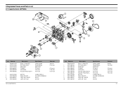
...;BUTYLENE,-,S-2000,- Description & Specification Remarks AH26-00265A TRANS POWER;-,MM-J4/J6,-,-,115/230V,-,-, AH39-00257A AH39-00257D POWER CORD;CP2,250V,2.5A,1830MM POWER CORD;CP2,KS,250V,2.5A,1830MM EUROPE KOREA AH39-00320C AH39-50030D AH42-20001P CBF COAXIAL CABLE;MAX-L68,110REC,-,1007# WIRE HARNESS;RING/REC,200mm,1007...MW/LW,FM64~108.0MHz TUNER-PACK ASSY;FM/MW/LW,FM87.5~108.0MHz TUNER-PACK ASSY;FM/MW/SW1/SW2 EUROPE(RDS) CIS(RDS) ASIA(T-BAND) CIS(NO RDS) LW BAND SW BAND AH59-01159J REMOCON-ASSY;MM-ZJ6,SAMSUNG,-,-,27KEY,-,- Description & Specification J28 R251 R201L R201R ...
...;BUTYLENE,-,S-2000,- Description & Specification Remarks AH26-00265A TRANS POWER;-,MM-J4/J6,-,-,115/230V,-,-, AH39-00257A AH39-00257D POWER CORD;CP2,250V,2.5A,1830MM POWER CORD;CP2,KS,250V,2.5A,1830MM EUROPE KOREA AH39-00320C AH39-50030D AH42-20001P CBF COAXIAL CABLE;MAX-L68,110REC,-,1007# WIRE HARNESS;RING/REC,200mm,1007...MW/LW,FM64~108.0MHz TUNER-PACK ASSY;FM/MW/LW,FM87.5~108.0MHz TUNER-PACK ASSY;FM/MW/SW1/SW2 EUROPE(RDS) CIS(RDS) ASIA(T-BAND) CIS(NO RDS) LW BAND SW BAND AH59-01159J REMOCON-ASSY;MM-ZJ6,SAMSUNG,-,-,27KEY,-,- Description & Specification J28 R251 R201L R201R ...
Service Manual
Page 10
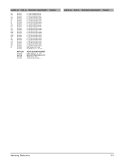
...,S CONNECTOR-HEADER;BOX,9P,1R,2.5mm,STRAIGH JACK-PHONE;11P,3.5PI,AG,BLK,VF DISPLAY;HNA-09MS17T,MM-J4/J6,100*25,1 COIL-CHOKE;27uH,K,Q30,-,-,DR(6.5*7.5),-, COIL-CHOKE;27uH,K,Q30,-,-,DR(6.5*7.5),-, LEAD CONNECTOR ASSY;-,5295,51004,2P,80MM MODULE REMOCON;KSM-913TE5,-,-,25CM,G.T:# CLAMP-CORD;-,-,-,-,-,A/S PART-POWE PCB;MM-J4,POWER PCB ASS'Y, A/S PART-FRONT;MM-ZJ6,FRONT PCB ASS'Y,-, DIODE-SWITCHING;1N4148...
...,S CONNECTOR-HEADER;BOX,9P,1R,2.5mm,STRAIGH JACK-PHONE;11P,3.5PI,AG,BLK,VF DISPLAY;HNA-09MS17T,MM-J4/J6,100*25,1 COIL-CHOKE;27uH,K,Q30,-,-,DR(6.5*7.5),-, COIL-CHOKE;27uH,K,Q30,-,-,DR(6.5*7.5),-, LEAD CONNECTOR ASSY;-,5295,51004,2P,80MM MODULE REMOCON;KSM-913TE5,-,-,25CM,G.T:# CLAMP-CORD;-,-,-,-,-,A/S PART-POWE PCB;MM-J4,POWER PCB ASS'Y, A/S PART-FRONT;MM-ZJ6,FRONT PCB ASS'Y,-, DIODE-SWITCHING;1N4148...
Service Manual
Page 11
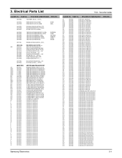
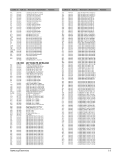
Description & Specification Remarks AC4L UC15 UC10 UC12 UC3 UC1 UC2 UC4 UC7 UC8 UC54 UC5 UE1 UC6 UC9 HL1R HL1L POWER EQ DOWN CD AUX UP TUNER TAPE STOP SPEED CON S.BASS REPEAT REC PF4*2 PF3*2 PF1*2 2202-000796 2202-000854 2203-000979 2203-000979 2203-000979 2203-...LEAD CONNECTOR ASSY;-,5295,51004,8P,210M WIRE HARNESS;-,RING,1007#24,60MM,BLK,-,CONNECT WIRE;MM-ZJ6/J4,-,-,9P,-,-,-,5100 LEAD CONNECTOR ASSY;MM-B7,1007#22,-,5P,2 STUD-TAP;-,T0.5,BT2,-,-,-,STUD-TAP;-,T0.5,BT2,-,-,-,HEAT SINK-,M;MM-J6,AL EXTR,-,-,-,-,-,CLAMP-CORD;-,-,-,-,-,DIODE-SWITCHING;1N4148,75V,150MA,DO-35,T DIODE-SWITCHING;1N4148...
Description & Specification Remarks AC4L UC15 UC10 UC12 UC3 UC1 UC2 UC4 UC7 UC8 UC54 UC5 UE1 UC6 UC9 HL1R HL1L POWER EQ DOWN CD AUX UP TUNER TAPE STOP SPEED CON S.BASS REPEAT REC PF4*2 PF3*2 PF1*2 2202-000796 2202-000854 2203-000979 2203-000979 2203-000979 2203-...LEAD CONNECTOR ASSY;-,5295,51004,8P,210M WIRE HARNESS;-,RING,1007#24,60MM,BLK,-,CONNECT WIRE;MM-ZJ6/J4,-,-,9P,-,-,-,5100 LEAD CONNECTOR ASSY;MM-B7,1007#22,-,5P,2 STUD-TAP;-,T0.5,BT2,-,-,-,STUD-TAP;-,T0.5,BT2,-,-,-,HEAT SINK-,M;MM-J6,AL EXTR,-,-,-,-,-,CLAMP-CORD;-,-,-,-,-,DIODE-SWITCHING;1N4148,75V,150MA,DO-35,T DIODE-SWITCHING;1N4148...
Service Manual
Page 13
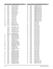
Location no . Description & Specification AC1L AC1R JC1 JC5R JC5L JC4 JC2 AC9 JC2R JC2L JC9L JC9R MC11L MC11R MC14L MC14R FC3R AC4 FC11L FC11R FC2L FC2R FC3L QL1 2401-...,5x11mm,5mm C-AL;2.2uF,20%,50V,GP,TP,5x11mm,5mm INDUCTOR-AXIAL;470uH,10%,4298 PCB MAIN;MM-J4/J6,FR1,1,-,1.6T,197*247, ASSY-CA'DECK;-,MMJ4/J6EUROOP,- Description & Specification Remarks Samsung Electronics 3-5 Code no . Remarks Location no . Code no . CONNECT WIRE;MM-J6,-,-,6P,-,-,-,51004,-, DECK-CASSETTE;CMAL6Z212A,MM-J4,-,-,DC12V SCREW;-,-,L8,YEL,+,-,-,M2.6,-,HOLDER-DECK...
Location no . Description & Specification AC1L AC1R JC1 JC5R JC5L JC4 JC2 AC9 JC2R JC2L JC9L JC9R MC11L MC11R MC14L MC14R FC3R AC4 FC11L FC11R FC2L FC2R FC3L QL1 2401-...,5x11mm,5mm C-AL;2.2uF,20%,50V,GP,TP,5x11mm,5mm INDUCTOR-AXIAL;470uH,10%,4298 PCB MAIN;MM-J4/J6,FR1,1,-,1.6T,197*247, ASSY-CA'DECK;-,MMJ4/J6EUROOP,- Description & Specification Remarks Samsung Electronics 3-5 Code no . Remarks Location no . Code no . CONNECT WIRE;MM-J6,-,-,6P,-,-,-,51004,-, DECK-CASSETTE;CMAL6Z212A,MM-J4,-,-,DC12V SCREW;-,-,L8,YEL,+,-,-,M2.6,-,HOLDER-DECK...
Service Manual
Page 15
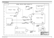
5. Wiring Diagram Samsung Electronics 5-1
5. Wiring Diagram Samsung Electronics 5-1
Service Manual
Page 16
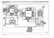
6. Samsung Electronics 6-1 This Document can not be used without Samsung's authorization - Schematic Diagram 6-1 CD Part -
6. Samsung Electronics 6-1 This Document can not be used without Samsung's authorization - Schematic Diagram 6-1 CD Part -
Service Manual
Page 17
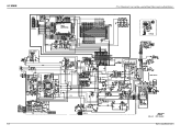
This Document can not be used without Samsung's authorization - 6-2 Samsung Electronics 6-2 MAIN -
This Document can not be used without Samsung's authorization - 6-2 Samsung Electronics 6-2 MAIN -
Service Manual
Page 18
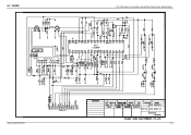
6-3 TUNER - Samsung Electronics 6-3 This Document can not be used without Samsung's authorization -
6-3 TUNER - Samsung Electronics 6-3 This Document can not be used without Samsung's authorization -

