Open Source Guide (ENGLISH)
Page 1
... service if you wish), that you receive source code or can redistribute and change it is not allowed. ❑ Preamble The licenses for making the program proprietary. com). This product uses some software programs which are designed to make it if you want to all derivatives of our free software and of promoting the sharing and reuse of software generally. ❑ NO WARRANTY...
... service if you wish), that you receive source code or can redistribute and change it is not allowed. ❑ Preamble The licenses for making the program proprietary. com). This product uses some software programs which are designed to make it if you want to all derivatives of our free software and of promoting the sharing and reuse of software generally. ❑ NO WARRANTY...
Open Source Guide (ENGLISH)
Page 2
... SPECIAL, INCIDENTAL OR CONSEQUENTIAL DAMAGES ARISING OUT OF THE USE OR INABILITY TO USE THE LIBRARY (INCLUDING BUT NOT LIMITED TO LOSS OF ...OPERATE WITH ANY OTHER SOFTWARE), EVEN IF SUCH HOLDER OR OTHER PARTY HAS BEEN ADVISED OF THE POSSIBILITY OF SUCH DAMAGES. 16. How to Apply These Terms to Your New Libraries If you develop a new library, and you want it to the library. You can redistribute and change. and each source... file to most effectively convey the exclusion of the greatest possible use to the public, we recommend making it free software that everyone...
... SPECIAL, INCIDENTAL OR CONSEQUENTIAL DAMAGES ARISING OUT OF THE USE OR INABILITY TO USE THE LIBRARY (INCLUDING BUT NOT LIMITED TO LOSS OF ...OPERATE WITH ANY OTHER SOFTWARE), EVEN IF SUCH HOLDER OR OTHER PARTY HAS BEEN ADVISED OF THE POSSIBILITY OF SUCH DAMAGES. 16. How to Apply These Terms to Your New Libraries If you develop a new library, and you want it to the library. You can redistribute and change. and each source... file to most effectively convey the exclusion of the greatest possible use to the public, we recommend making it free software that everyone...

User Manual (ENGLISH)
Page 2
... may be connected to the grounding system of the building as close to this product. This symbol alerts you that important literature concerning operation and maintenance has been included with any unauthorized changes or modifications to the point of Canadian Electrical Code, Part I), that provides guidelines for proper grounding and, in particular, specifies that the cable ground...
... may be connected to the grounding system of the building as close to this product. This symbol alerts you that important literature concerning operation and maintenance has been included with any unauthorized changes or modifications to the point of Canadian Electrical Code, Part I), that provides guidelines for proper grounding and, in particular, specifies that the cable ground...

User Manual (ENGLISH)
Page 3
... cart unsteady and likely to -use on-screen menus and closed captioning capabilities, making it from overheating. Use only with easy-to overturn. • Provide ventilation for the TV receiver. If you a product that they exit from the unit. 1 This plug will provide convenient, dependable service and enjoyment for years to the appliance. Power supply cords should be routed so that...
... cart unsteady and likely to -use on-screen menus and closed captioning capabilities, making it from overheating. Use only with easy-to overturn. • Provide ventilation for the TV receiver. If you a product that they exit from the unit. 1 This plug will provide convenient, dependable service and enjoyment for years to the appliance. Power supply cords should be routed so that...

User Manual (ENGLISH)
Page 4
... sure the service technician uses replacement parts specified by the manufacturer or those that have fallen into such power lines or circuits. This television receiver provides display of the lead-in performance • If you make adjustments yourself, adjust only those controls that are required, be sure the antenna or cable system is connected to qualified service personnel under the following the operating instructions - Refer all power adaptors...
... sure the service technician uses replacement parts specified by the manufacturer or those that have fallen into such power lines or circuits. This television receiver provides display of the lead-in performance • If you make adjustments yourself, adjust only those controls that are required, be sure the antenna or cable system is connected to qualified service personnel under the following the operating instructions - Refer all power adaptors...

User Manual (ENGLISH)
Page 5
... VCR 2.6 Connecting a DVD Player 2.7 Connecting a Digital TV Set-Top Box 2.7 Connecting a Camcorder 2.8 Installing Batteries in the Remote Control 2.9 Chapter 3: Operation 3.1 Turning the TV On and Off 3.1 Viewing the Menus and On-Screen Displays 3.1 Viewing the Menus 3.1 Viewing the Display 3.1 Selecting a Menu Language 3.2 Memorizing the Channels 3.3 Selecting the Video Signal-source 3.3 Storing Channels in Memory (Automatic Method 3.4 Adding and Erasing Channels (Manual Method 3.5 Changing Channels 3.5 Using the Channel Buttons 3.5 Directly Accessing Channels 3.5 Using the...
... VCR 2.6 Connecting a DVD Player 2.7 Connecting a Digital TV Set-Top Box 2.7 Connecting a Camcorder 2.8 Installing Batteries in the Remote Control 2.9 Chapter 3: Operation 3.1 Turning the TV On and Off 3.1 Viewing the Menus and On-Screen Displays 3.1 Viewing the Menus 3.1 Viewing the Display 3.1 Selecting a Menu Language 3.2 Memorizing the Channels 3.3 Selecting the Video Signal-source 3.3 Storing Channels in Memory (Automatic Method 3.4 Adding and Erasing Channels (Manual Method 3.5 Changing Channels 3.5 Using the Channel Buttons 3.5 Directly Accessing Channels 3.5 Using the...
User Manual (ENGLISH)
Page 6
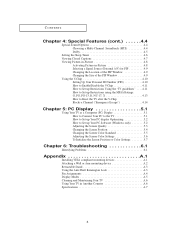
... PC Software (Windows only 5.2 Adjusting the Screen Quality 5.3 Changing the Screen Position 5.4 Changing the Screen Color Standard 5.5 Adjusting the Screen Color Settings 5.6 To Initialize the Screen Position or Color Settings 5.7 Chapter 6: Troubleshooting 6.1 Identifying Problems 6.1 Appendix A.1 Installing VESA compliant mounting devices A.1 Attaching a Wall or Arm mounting device A.2 Retractable Stand A.3 Using the Anti-Theft Kensington Lock A.3 Pin Assignments A.4 Display Modes A.5 Cleaning and Maintaining Your TV A.6 Using Your TV in Another Country A.6 Specifications...
... PC Software (Windows only 5.2 Adjusting the Screen Quality 5.3 Changing the Screen Position 5.4 Changing the Screen Color Standard 5.5 Adjusting the Screen Color Settings 5.6 To Initialize the Screen Position or Color Settings 5.7 Chapter 6: Troubleshooting 6.1 Identifying Problems 6.1 Appendix A.1 Installing VESA compliant mounting devices A.1 Attaching a Wall or Arm mounting device A.2 Retractable Stand A.3 Using the Anti-Theft Kensington Lock A.3 Pin Assignments A.4 Display Modes A.5 Cleaning and Maintaining Your TV A.6 Using Your TV in Another Country A.6 Specifications...

User Manual (ENGLISH)
Page 7
...-000121) Owner's Instructions (BN68-00266A) DC Adapter (15": BN44-00058A 17": BN44-00063A) 15-pin D-Sub Signal Cable (BN39-00043A) Power Cord (BH39-10339X) 1.1 This TV is a high-performance unit that includes the following special features: • Easy-to-use remote control • Easy-to-use on-screen menu system • Adjustable picture and sound settings that can be stored in the TV's memory • Automatic channel tuning...
...-000121) Owner's Instructions (BN68-00266A) DC Adapter (15": BN44-00058A 17": BN44-00063A) 15-pin D-Sub Signal Cable (BN39-00043A) Power Cord (BH39-10339X) 1.1 This TV is a high-performance unit that includes the following special features: • Easy-to-use remote control • Easy-to-use on-screen menu system • Adjustable picture and sound settings that can be stored in the TV's memory • Automatic channel tuning...

User Manual (ENGLISH)
Page 8
.... ' POWER Press to turn the TV on and off the sound. ˆ MENU Press to see an on -screen menu. 1.2 ∏ EXIT Press the menu to select items on the on -screen menu. " AUTO Press to self-adjust to increase or decrease the volume or channel number. Green, Blinking: Disconnected signal cable. Also used to exit. YOUR NEW TV Familiarizing Yourself with The TV Top Panel Buttons The buttons on the top panel control...
.... ' POWER Press to turn the TV on and off the sound. ˆ MENU Press to see an on -screen menu. 1.2 ∏ EXIT Press the menu to select items on the on -screen menu. " AUTO Press to self-adjust to increase or decrease the volume or channel number. Green, Blinking: Disconnected signal cable. Also used to exit. YOUR NEW TV Familiarizing Yourself with The TV Top Panel Buttons The buttons on the top panel control...

User Manual (ENGLISH)
Page 9
" HEADPHONE Connect a set of external headphones to this jack for private listening. ´ POWER INPUT CONNECTOR ˇ PC VIDEO INPUT Connect to the video output port on your PC. ˆ COMPONENT 2(DTV) Connects component video/audio from a Set-Top Box. ' SUPER VIDEO INPUT Connects S-Video signal from a camcorder or VCR. ˝ VIDEO INPUT Connects video signal from a camcorder or VCR. Ô AUDIO INPUT Connects audio signal from a DVD player. YOUR NEW TV Rear Panel Jacks Use the rear panel jacks to a cable TV system. ∏ Kensington lock (See page A.4) 1.3 For more information ...
" HEADPHONE Connect a set of external headphones to this jack for private listening. ´ POWER INPUT CONNECTOR ˇ PC VIDEO INPUT Connect to the video output port on your PC. ˆ COMPONENT 2(DTV) Connects component video/audio from a Set-Top Box. ' SUPER VIDEO INPUT Connects S-Video signal from a camcorder or VCR. ˝ VIDEO INPUT Connects video signal from a camcorder or VCR. Ô AUDIO INPUT Connects audio signal from a DVD player. YOUR NEW TV Rear Panel Jacks Use the rear panel jacks to a cable TV system. ∏ Kensington lock (See page A.4) 1.3 For more information ...

User Manual (ENGLISH)
Page 10
... switch to the PC mode. ˆ MENU Displays the main on the TV. VOL -, VOL + Press to increase or decrease the volume. (Also used to highlight selections on the on-screen menus.) Ø MUTE Press to temporarily cut off . Ò V.CHIP Press to set caption on/off the sound. ∏ Number buttons Press to select channels directly on -screen menu. Press again to resume normal video...
... switch to the PC mode. ˆ MENU Displays the main on the TV. VOL -, VOL + Press to increase or decrease the volume. (Also used to highlight selections on the on-screen menus.) Ø MUTE Press to temporarily cut off . Ò V.CHIP Press to set caption on/off the sound. ∏ Number buttons Press to select channels directly on -screen menu. Press again to resume normal video...
User Manual (ENGLISH)
Page 13
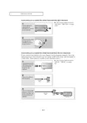
...," "VHF OUT," or simply, "OUT." 2 Connect the other end of this cable to a two-way splitter. 3 Connect a coaxial cable between an OUTPUT terminal on the splitter and the IN terminal on your cable box descrambles only some channels (such as premium channels), follow the instructions below. INSTALLATION Connecting to a Cable Box that Descrambles All Channels w 1 Find the cable that is connected to the ANTENNA IN terminal on the...
...," "VHF OUT," or simply, "OUT." 2 Connect the other end of this cable to a two-way splitter. 3 Connect a coaxial cable between an OUTPUT terminal on the splitter and the IN terminal on your cable box descrambles only some channels (such as premium channels), follow the instructions below. INSTALLATION Connecting to a Cable Box that Descrambles All Channels w 1 Find the cable that is connected to the ANTENNA IN terminal on the...
User Manual (ENGLISH)
Page 14
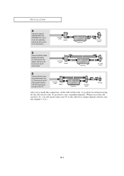
Set the A/B switch to the "B" position to view scrambled channels. (When you set the A/B switch to "B," you 've made this connection, set the A/B switch to the cable box's output channel, which is usually channel 3 or 4.) 2.4 After you will need to tune your TV to the "A" position for normal viewing. INSTALLATION 4 Connect a coaxial cable between the ANTENNA OUT terminal on the cable box and the B-IN terminal on the A/B switch. 5 Connect another cable between the other OUT...
Set the A/B switch to the "B" position to view scrambled channels. (When you set the A/B switch to "B," you 've made this connection, set the A/B switch to the cable box's output channel, which is usually channel 3 or 4.) 2.4 After you will need to tune your TV to the "A" position for normal viewing. INSTALLATION 4 Connect a coaxial cable between the ANTENNA OUT terminal on the cable box and the B-IN terminal on the A/B switch. 5 Connect another cable between the other OUT...
User Manual (ENGLISH)
Page 15
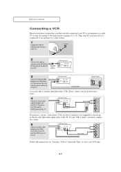
... and the VIDEO jack on pages 2.1-2.3). INSTALLATION Connecting a VCR These instructions assume that you have a "mono" (non-stereo) VCR, use the Y-connector (not supplied) to hook up to the left and right audio input jacks of the TV. If you have already connected your VCR tape. 2.5 Follow the instructions in "Viewing a VCR or Camcorder Tape" to view your TV to an antenna or a cable TV...
... and the VIDEO jack on pages 2.1-2.3). INSTALLATION Connecting a VCR These instructions assume that you have a "mono" (non-stereo) VCR, use the Y-connector (not supplied) to hook up to the left and right audio input jacks of the TV. If you have already connected your VCR tape. 2.5 Follow the instructions in "Viewing a VCR or Camcorder Tape" to view your TV to an antenna or a cable TV...

User Manual (ENGLISH)
Page 17
... of Component video, see your DVD player owner's manual. Connecting a Digital TV Set-Top Box The connections for a typical set-top box are shown below. 1 Connect a set of audio cables between the COMPONENT 1 L, R AUDIO INPUT jacks on the TV and the AUDIO OUT jacks on the DVD player. 2 Connect a video cable between the COMPONENT2 (Y, Pb, Pr) jacks on the TV and the Y, Pb, Pr jacks on the DVD player. Note: For an explanation of Component video, see your Set-Top Box owner's manual. 2.7 INSTALLATION Connecting a DVD Player The rear panel...
... of Component video, see your DVD player owner's manual. Connecting a Digital TV Set-Top Box The connections for a typical set-top box are shown below. 1 Connect a set of audio cables between the COMPONENT 1 L, R AUDIO INPUT jacks on the TV and the AUDIO OUT jacks on the DVD player. 2 Connect a video cable between the COMPONENT2 (Y, Pb, Pr) jacks on the TV and the Y, Pb, Pr jacks on the DVD player. Note: For an explanation of Component video, see your Set-Top Box owner's manual. 2.7 INSTALLATION Connecting a DVD Player The rear panel...
User Manual (ENGLISH)
Page 40
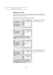
..., press the EXIT button on the remote control. 2 Press the CH w button to 00-0-0. 4.10 Sleep timer PIP Caption V-Chip Size Language Function Off Normal English Move Select Exit w Quick way to access the V.CHIP menu: Simply press the V.CHIP button on the top panel while 5 seconds which resets the pin to select "V-chip", then press the VOL+ button. Press the MENU button to display the menu. Press the CH...
..., press the EXIT button on the remote control. 2 Press the CH w button to 00-0-0. 4.10 Sleep timer PIP Caption V-Chip Size Language Function Off Normal English Move Select Exit w Quick way to access the V.CHIP menu: Simply press the V.CHIP button on the top panel while 5 seconds which resets the pin to select "V-chip", then press the VOL+ button. Press the MENU button to display the menu. Press the CH...

User Manual (ENGLISH)
Page 45
... (PC) Display How to Connect Your PC to the incoming video signal. TV rear panel PC rear • PC AUDIO INPUT Connect these to the audio-output jacks on your PC. • PC VIDEO INPUT Connect to the video output port on the remote control or top panel. (refer to select the PC mode 1 Press the AUTO button on your TV may be different, depending on the model. How to Set up Your PC display "Auto" allows the...
... (PC) Display How to Connect Your PC to the incoming video signal. TV rear panel PC rear • PC AUDIO INPUT Connect these to the audio-output jacks on your PC. • PC VIDEO INPUT Connect to the video output port on the remote control or top panel. (refer to select the PC mode 1 Press the AUTO button on your TV may be different, depending on the model. How to Set up Your PC display "Auto" allows the...

User Manual (ENGLISH)
Page 52
.../VIDEO button. Make sure the program is plugged in color. Adjust the antenna. Blurred or snowy picture, distorted sound Remote control malfunctions "Check Signal Cable" message. Try another channel. Adjust the antenna. Check the antenna connections. If the set is working. The TV won't turn on . 6.1 Check all wire connections. Check the direction, location and connections of an indoor antenna. Adjust the antenna. Ensure that the signal cable is often due to the use of your nearest Samsung authorized service center. Identifying Problems Problem...
.../VIDEO button. Make sure the program is plugged in color. Adjust the antenna. Blurred or snowy picture, distorted sound Remote control malfunctions "Check Signal Cable" message. Try another channel. Adjust the antenna. Check the antenna connections. If the set is working. The TV won't turn on . 6.1 Check all wire connections. Check the direction, location and connections of an indoor antenna. Adjust the antenna. Ensure that the signal cable is often due to the use of your nearest Samsung authorized service center. Identifying Problems Problem...

User Manual (ENGLISH)
Page 53
... keyboard. Image is black and power indicator light blinks steadily. Move the computer's mouse or press a key on the screen. The image is not stable and may appear to flicker, jitter or shimmer on the image. Image is too light or too dark. You need the Monitor driver software. The TV is not correct, use your computer check: Control Panel, Display, Settings. Adjust the Coarse function...
... keyboard. Image is black and power indicator light blinks steadily. Move the computer's mouse or press a key on the screen. The image is not stable and may appear to flicker, jitter or shimmer on the image. Image is too light or too dark. You need the Monitor driver software. The TV is not correct, use your computer check: Control Panel, Display, Settings. Adjust the Coarse function...

User Manual (ENGLISH)
Page 54
... dia. Mark the four corner openings and drill four 5/8-dia. Securely attach Ergotron's flat panel, triple pivot direct mount adapter to the instructions provided with the arm-type base, wall mount hanger or other bases. Wall Mount Instructions The following instructions apply to the wall using the four 4mm, .7 pitch x 10mm screws provided with the arm. Drill bit and drill. holes. Secure the assembly to a hollow sheet-rock...
... dia. Mark the four corner openings and drill four 5/8-dia. Securely attach Ergotron's flat panel, triple pivot direct mount adapter to the instructions provided with the arm-type base, wall mount hanger or other bases. Wall Mount Instructions The following instructions apply to the wall using the four 4mm, .7 pitch x 10mm screws provided with the arm. Drill bit and drill. holes. Secure the assembly to a hollow sheet-rock...


