User Manual (ENGLISH)
Page 6
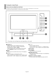
To use the more advanced features, you would use the and buttons on and lights up in stand-by mode. MENU Press to turn the TV on and off when the power is on the remote control. English-4 Viewing the Control Panel Buttons on the Lower-Right Part of the Panel ..., Component1, Component2, PC, HDMI1, HDMI2). In the on-screen menu, use the ENTER button on the TV. In the on-screen menu, use the buttons as you must use the and buttons on the model. Press to increase or decrease the volume. REMOTE CONTROL SENSOR Aim the remote control towards this button...
To use the more advanced features, you would use the and buttons on and lights up in stand-by mode. MENU Press to turn the TV on and off when the power is on the remote control. English-4 Viewing the Control Panel Buttons on the Lower-Right Part of the Panel ..., Component1, Component2, PC, HDMI1, HDMI2). In the on-screen menu, use the ENTER button on the TV. In the on-screen menu, use the buttons as you must use the and buttons on the model. Press to increase or decrease the volume. REMOTE CONTROL SENSOR Aim the remote control towards this button...
User Manual (ENGLISH)
Page 7
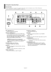
... to a Digital Audio component. ANT 1 IN/ANT 2 IN Connect to an antenna or cable TV system. AV OUT Connect to the audio input jacks on its model. The place of a device with a DVI output. If you purchased the TV. For more information on your Amplifier/ Home theater. PC IN Connect to the video...
... to a Digital Audio component. ANT 1 IN/ANT 2 IN Connect to an antenna or cable TV system. AV OUT Connect to the audio input jacks on its model. The place of a device with a DVI output. If you purchased the TV. For more information on your Amplifier/ Home theater. PC IN Connect to the video...
User Manual (ENGLISH)
Page 89
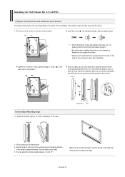
...top in step 2 (plastic hanger + screw ) to the rear holes of the product. English-87 LCD TV How to Adjust Mounting Angle Adjust the bracket angle to -2° before installing it is firmly fixed to...sure the wall bracket is securely fixed to the wall, or the product may vary depending on the model. (The assemblies of the plastic hanger and the screw are the same) 2 Remove the 4 screws...bracket holes ( ). Wall Bracket Wall 1. Installing the Wall Mount Kit (LN-S4695D) Fixing the TV panel to the wall attachment panel bracket The shape of the product may not stay in place...
...top in step 2 (plastic hanger + screw ) to the rear holes of the product. English-87 LCD TV How to Adjust Mounting Angle Adjust the bracket angle to -2° before installing it is firmly fixed to...sure the wall bracket is securely fixed to the wall, or the product may vary depending on the model. (The assemblies of the plastic hanger and the screw are the same) 2 Remove the 4 screws...bracket holes ( ). Wall Bracket Wall 1. Installing the Wall Mount Kit (LN-S4695D) Fixing the TV panel to the wall attachment panel bracket The shape of the product may not stay in place...
User Manual (ENGLISH)
Page 90
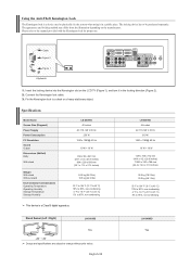
... apparatus. Insert the locking device into the Kensington slot on the manufacturer. Specifications Model Name Screen Size (Diagonal) Power Supply Power Consumption PC Resolution Sound Output Dimensions ...10% to 80%, non-condensing -4 °F to 113 °F (-20 °C to 45 °C) 5% to 95%, non-condensing LN-S4695D 46 inches AC 110-120 V 60 Hz 310 W 1920 x 1080@ 60 Hz 10 W + 10 W 1129 x 106 x 732 mm... may differ from the illustration depending on the LCD TV (Figure 1), and turn it in the locking direction (Figure 2). 2. English-88 LN-S4695D Yes Cable Figure 2 Figure 1 1. The ...
... apparatus. Insert the locking device into the Kensington slot on the manufacturer. Specifications Model Name Screen Size (Diagonal) Power Supply Power Consumption PC Resolution Sound Output Dimensions ...10% to 80%, non-condensing -4 °F to 113 °F (-20 °C to 45 °C) 5% to 95%, non-condensing LN-S4695D 46 inches AC 110-120 V 60 Hz 310 W 1920 x 1080@ 60 Hz 10 W + 10 W 1129 x 106 x 732 mm... may differ from the illustration depending on the LCD TV (Figure 1), and turn it in the locking direction (Figure 2). 2. English-88 LN-S4695D Yes Cable Figure 2 Figure 1 1. The ...


