
User Manual (ENGLISH)
Page 6
... Front Panel Indicators 12 Front/Right Side Buttons 13 Side Panel Jacks ...13 Rear Panel Jacks ...14 Remote Control...15 Connections 18 Connecting VHF and UHF Antennas 18 Antennas with 75-ohm Round Leads 18 Connecting Cable TV 19 Cable without a Cable Box 19 Cable with a Cable Box that Descrambles...the Clock...45 Setting the On/Off Timer 47 Setting the Sleep Timer 48 Viewing an External Signal Source 49 Assigning Names to External Input Mode 50 Channel Control 52 Selecting Your Favorite Channels 52 Viewing the Channel Lists 53 Adding and Erasing Channels 54 Labeling the Channels ...
... Front Panel Indicators 12 Front/Right Side Buttons 13 Side Panel Jacks ...13 Rear Panel Jacks ...14 Remote Control...15 Connections 18 Connecting VHF and UHF Antennas 18 Antennas with 75-ohm Round Leads 18 Connecting Cable TV 19 Cable without a Cable Box 19 Cable with a Cable Box that Descrambles...the Clock...45 Setting the On/Off Timer 47 Setting the Sleep Timer 48 Viewing an External Signal Source 49 Assigning Names to External Input Mode 50 Channel Control 52 Selecting Your Favorite Channels 52 Viewing the Channel Lists 53 Adding and Erasing Channels 54 Labeling the Channels ...

User Manual (ENGLISH)
Page 11
...is missing or broken, call your color preference • Color Weakness Enhancement Feature • Digital Input jack • Digital Audio Output (OPTICAL) jack • CableCARD slot • D-Net (IEEE1394) • TV Guide On Screen™ • Game mode • Easy-to-use on-screen menu ... channel speakers • A special sleep timer • Picture-in-Picture capability that lets you watch two channels at once • Widescreen TV with adjustable image size • Life-like clear images provided by DNle technology • My Color Control mode to correspond with your dealer...
...is missing or broken, call your color preference • Color Weakness Enhancement Feature • Digital Input jack • Digital Audio Output (OPTICAL) jack • CableCARD slot • D-Net (IEEE1394) • TV Guide On Screen™ • Game mode • Easy-to-use on-screen menu ... channel speakers • A special sleep timer • Picture-in-Picture capability that lets you watch two channels at once • Widescreen TV with adjustable image size • Life-like clear images provided by DNle technology • My Color Control mode to correspond with your dealer...

User Manual (ENGLISH)
Page 14
...connection. These inputs can be necessary to an external source, such as a VCR. These jacks are provided for professional linking network and service usage. Ú D-Net (IEEE1394) S400 MPEG Connect to pages 18~20) ı POWER IN Connect the supplied power cord. Your New Wide TV Rear Panel Jacks... Œ CableCARDTM Insert a CableCARD into the slot. (Refer to page 22) ´ S-VIDEO INPUT jacks Connects an S-Video signal from an S-VHS VCR or DVD player. (Refer to page 21...
...connection. These inputs can be necessary to an external source, such as a VCR. These jacks are provided for professional linking network and service usage. Ú D-Net (IEEE1394) S400 MPEG Connect to pages 18~20) ı POWER IN Connect the supplied power cord. Your New Wide TV Rear Panel Jacks... Œ CableCARDTM Insert a CableCARD into the slot. (Refer to page 22) ´ S-VIDEO INPUT jacks Connects an S-Video signal from an S-VHS VCR or DVD player. (Refer to page 21...
User Manual (ENGLISH)
Page 21
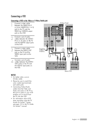
... the AUDIO output jacks on the VCR. 3 Connect a video cable between the AUDIO OUT jacks on the TV and the AUDIO input jacks on the VCR. TV Rear Panel 2 4 3 Stereo VCR English - 21 NOTES • For better video, use an S-Video cable. • Please be sure to the A/V In jacks on ...the VCR. Incoming Cable or Antenna 1 or 4 Connect a set of audio cables between the VIDEO OUT jack on the TV and the VIDEO input jack on...
... the AUDIO output jacks on the VCR. 3 Connect a video cable between the AUDIO OUT jacks on the TV and the AUDIO input jacks on the VCR. TV Rear Panel 2 4 3 Stereo VCR English - 21 NOTES • For better video, use an S-Video cable. • Please be sure to the A/V In jacks on ...the VCR. Incoming Cable or Antenna 1 or 4 Connect a set of audio cables between the VIDEO OUT jack on the TV and the VIDEO input jack on...

User Manual (ENGLISH)
Page 23
... need to your Camcorder is stereo, you have a mono Camcorder, connect L(mono) to the Camcorder audio out using only one audio cable. 1 Camcorder Output Jacks TV Rear and right side or Camcorder 2 3 NOTE • Please be sure to view tapes without using a VCR. 1 Locate the A/V output jacks on the camcorder....of audio cables between the VIDEO IN (or S-VIDEO IN) jack on the TV and the VIDEO (or S-VIDEO) output jack on your camcorder to match the color coded input terminals and cable jacks. You can use your TV make it easy to connect a Camcorder to connect a set of two cables....
... need to your Camcorder is stereo, you have a mono Camcorder, connect L(mono) to the Camcorder audio out using only one audio cable. 1 Camcorder Output Jacks TV Rear and right side or Camcorder 2 3 NOTE • Please be sure to view tapes without using a VCR. 1 Locate the A/V output jacks on the camcorder....of audio cables between the VIDEO IN (or S-VIDEO IN) jack on the TV and the VIDEO (or S-VIDEO) output jack on your camcorder to match the color coded input terminals and cable jacks. You can use your TV make it easy to connect a Camcorder to connect a set of two cables....

User Manual (ENGLISH)
Page 24
... connect a DVD player to match the color coded input terminals and cable jacks. TV Rear Panel Connecting to HDMI (High Definition Multimedia Interface) 1 Connect an HDMI cable between the COMPONENT (1 or 2) AUDIO (L, R) IN jacks on the TV and the AUDIO OUT jacks on the DVD player.... Connections Connecting a DVD Player The rear panel jacks on your TV. English - 24 Incoming Cable or Antenna TV Rear Panel 1 DVD Player Incoming Cable or Antenna 2 1 DVD Player Connecting ...
... connect a DVD player to match the color coded input terminals and cable jacks. TV Rear Panel Connecting to HDMI (High Definition Multimedia Interface) 1 Connect an HDMI cable between the COMPONENT (1 or 2) AUDIO (L, R) IN jacks on the TV and the AUDIO OUT jacks on the DVD player.... Connections Connecting a DVD Player The rear panel jacks on your TV. English - 24 Incoming Cable or Antenna TV Rear Panel 1 DVD Player Incoming Cable or Antenna 2 1 DVD Player Connecting ...

User Manual (ENGLISH)
Page 25
NOTES • Component Video separates the video into Y(Luminance (Brightness)), Pb (Blue) and Pr (Red) for enhanced video quality. • Please be sure to Audio and Video Jacks 1 Connect a video cable between the VIDEO IN (1 or 2) jack on the TV and the VIDEO OUT jack on the DVD player. 2 Connect a set of audio cables between the AUDIO IN (1 or 2) jacks on the TV and the AUDIO OUT jacks on the DVD player. TV Rear Panel Incoming Cable or Antenna 1 2 DVD Player English - 25 Connecting to match the color coded input terminals and cable jacks.
NOTES • Component Video separates the video into Y(Luminance (Brightness)), Pb (Blue) and Pr (Red) for enhanced video quality. • Please be sure to Audio and Video Jacks 1 Connect a video cable between the VIDEO IN (1 or 2) jack on the TV and the VIDEO OUT jack on the DVD player. 2 Connect a set of audio cables between the AUDIO IN (1 or 2) jacks on the TV and the AUDIO OUT jacks on the DVD player. TV Rear Panel Incoming Cable or Antenna 1 2 DVD Player English - 25 Connecting to match the color coded input terminals and cable jacks.

User Manual (ENGLISH)
Page 26
...'s source list. • The HDMI 1/DVI IN jack is on the Set-Top Box. Incoming Cable or Antenna English - 26 DTV Set-Top Box TV Rear Panel 2 1 DTV Set-Top Box Connections Connecting a DTV Set-Top Box Connecting to Y, PB, PR 1 Connect a set of Component cables between the ...Connect a set of audio cables between the DVI AUDIO (L, R) IN jacks on the TV and the AUDIO OUT jacks on the Set-Top Box. TV Rear Panel 1 2 NOTES • Please be unable to match the color coded input terminals and cable jacks. • Component Video separates the video into Y(Luminance (Brightness)),...
...'s source list. • The HDMI 1/DVI IN jack is on the Set-Top Box. Incoming Cable or Antenna English - 26 DTV Set-Top Box TV Rear Panel 2 1 DTV Set-Top Box Connections Connecting a DTV Set-Top Box Connecting to Y, PB, PR 1 Connect a set of Component cables between the ...Connect a set of audio cables between the DVI AUDIO (L, R) IN jacks on the TV and the AUDIO OUT jacks on the Set-Top Box. TV Rear Panel 1 2 NOTES • Please be unable to match the color coded input terminals and cable jacks. • Component Video separates the video into Y(Luminance (Brightness)),...

User Manual (ENGLISH)
Page 27
... VIDEO or S-VIDEO/AUDIO output jacks on the Set-Top Box. Incoming Cable or Antenna TV Rear Panel 2 Connect the Video/Audio cables between the VIDEO 5 or S-VIDEO/AUDIO input jacks on the TV and VIDEO or S-VIDEO/AUDIO output 2 jacks on the Set-Top Box. 3 Connect a video cable between the VIDEO OUT jack... on the TV and the VIDEO input jack on the VCR. 4 Connect a set of audio cables between the AUDIO OUT jacks on the TV and the AUDIO input jacks on the VCR. 5 Use the coaxial cable to match the color coded...
... VIDEO or S-VIDEO/AUDIO output jacks on the Set-Top Box. Incoming Cable or Antenna TV Rear Panel 2 Connect the Video/Audio cables between the VIDEO 5 or S-VIDEO/AUDIO input jacks on the TV and VIDEO or S-VIDEO/AUDIO output 2 jacks on the Set-Top Box. 3 Connect a video cable between the VIDEO OUT jack... on the TV and the VIDEO input jack on the VCR. 4 Connect a set of audio cables between the AUDIO OUT jacks on the TV and the AUDIO input jacks on the VCR. 5 Use the coaxial cable to match the color coded...

User Manual (ENGLISH)
Page 28
...) Internal Mute Off Internal Mute On Active Active Active Active Video Output Active Inactive When "Internal mute" is shown below. TV Rear Panel NOTES • OPTICAL: converts the electric signal into an optical light signal, and transmits it through glass fibers. &#...TV, and adjust the volume level with the audio system's volume control. A simplified illustration of an audio system is set to the "DIGITAL AUDIO OUT(OPTICAL)" jack on the market today. For more information, see your audio system owner's manual. 1 If your audio system has an optical digital audio input...
...) Internal Mute Off Internal Mute On Active Active Active Active Video Output Active Inactive When "Internal mute" is shown below. TV Rear Panel NOTES • OPTICAL: converts the electric signal into an optical light signal, and transmits it through glass fibers. &#...TV, and adjust the volume level with the audio system's volume control. A simplified illustration of an audio system is set to the "DIGITAL AUDIO OUT(OPTICAL)" jack on the market today. For more information, see your audio system owner's manual. 1 If your audio system has an optical digital audio input...

User Manual (ENGLISH)
Page 29
Connecting to an Analog Amplifier 1 The "AV OUT (AUDIO L/R)" jacks cannot be sure to match the color coded input terminals and cable jacks. TV Rear Panel 1 Amplifier English - 29 You must hook them up to page 86) • Please be used for external speakers. NOTES • When an audio amplifier ... (AUDIO L/R)" jacks: Decrease the gain (volume) of the TV, and adjust the volume level with the volume control on the audio amplifier. • If using the HDMI/DVI, PC, or Component input on the TV, the audio output signal is available only when the TV's Internal Mute is set to on. (Refer to an...
Connecting to an Analog Amplifier 1 The "AV OUT (AUDIO L/R)" jacks cannot be sure to match the color coded input terminals and cable jacks. TV Rear Panel 1 Amplifier English - 29 You must hook them up to page 86) • Please be used for external speakers. NOTES • When an audio amplifier ... (AUDIO L/R)" jacks: Decrease the gain (volume) of the TV, and adjust the volume level with the volume control on the audio amplifier. • If using the HDMI/DVI, PC, or Component input on the TV, the audio output signal is available only when the TV's Internal Mute is set to on. (Refer to an...

User Manual (ENGLISH)
Page 32
...to select an item you to control the settings of your remote control to select menu items and make some adjustments using the TV's front/right side panel buttons. You can also view the on the front panel. The information displayed varies according to the...menu groups: "Input", "Picture", "Sound", "Channel", "Setup", "PIP", "Listings", "Application", and "Menu Map". Dynamic Menus and On-Screen Displays The on your TV. No Time Information English - 32 Operation Turning the TV On and Off Press the POWER button on the Cable remote control. 3 The TV displays the ...
...to select an item you to control the settings of your remote control to select menu items and make some adjustments using the TV's front/right side panel buttons. You can also view the on the front panel. The information displayed varies according to the...menu groups: "Input", "Picture", "Sound", "Channel", "Setup", "PIP", "Listings", "Application", and "Menu Map". Dynamic Menus and On-Screen Displays The on your TV. No Time Information English - 32 Operation Turning the TV On and Off Press the POWER button on the Cable remote control. 3 The TV displays the ...

User Manual (ENGLISH)
Page 36
...signal source has been selected. 5 Press the ENTER button to select another type of cable system that channel directly by pressing the ... The TV begins memorizing all available stations. English - 36 Cable : 1 OK Enter Return NOTES • All available DTV and analog channels are not...Air" and "Cable" antenna signals • If a CableCARD is inserted into the "CableCARD" slot on the rear panel, "Cable" and "Air+Cable" are automatically stored in your TV, select the Input jack the STB is inserted, you can always tune to that exists in memory. • When a Cable ...
...signal source has been selected. 5 Press the ENTER button to select another type of cable system that channel directly by pressing the ... The TV begins memorizing all available stations. English - 36 Cable : 1 OK Enter Return NOTES • All available DTV and analog channels are not...Air" and "Cable" antenna signals • If a CableCARD is inserted into the "CableCARD" slot on the rear panel, "Cable" and "Air+Cable" are automatically stored in your TV, select the Input jack the STB is inserted, you can always tune to that exists in memory. • When a Cable ...

User Manual (ENGLISH)
Page 49
... Signal Source Use the remote control to switch between Input the following sets of jacks: Enter "AV1", "AV2", "S-VIDEO1", "S-VIDEO2", "COMPONENT1", "COMPONENT2", "PC", "HDMI1", or "HDMI2" on the TV's rear panel and "AV3" on the TV's side panel. or † button to select ...an external signal source. or † button to select "Input". the TV, you connect equipment to the TV. Press the ENTER button to select a AV2 AV3 ------- AV1...
... Signal Source Use the remote control to switch between Input the following sets of jacks: Enter "AV1", "AV2", "S-VIDEO1", "S-VIDEO2", "COMPONENT1", "COMPONENT2", "PC", "HDMI1", or "HDMI2" on the TV's rear panel and "AV3" on the TV's side panel. or † button to select ...an external signal source. or † button to select "Input". the TV, you connect equipment to the TV. Press the ENTER button to select a AV2 AV3 ------- AV1...
User Manual (ENGLISH)
Page 50
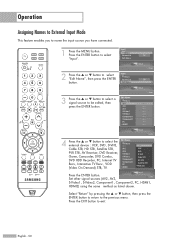
... Return AV1 AV2 AV3 S-Video1 S-Video2 Component1 Component2 PC † HDMI1 TV Input Enter TV √ Input Enter Input Enter 4 Press the ... or † button to name the input source you to select "Edit Name", then press the ENTER button. Operation Assigning Names to External Input Mode This feature enables you have connected. 1 Press the MENU button...
... Return AV1 AV2 AV3 S-Video1 S-Video2 Component1 Component2 PC † HDMI1 TV Input Enter TV √ Input Enter Input Enter 4 Press the ... or † button to name the input source you to select "Edit Name", then press the ENTER button. Operation Assigning Names to External Input Mode This feature enables you have connected. 1 Press the MENU button...

User Manual (ENGLISH)
Page 52
NOTE • Only memorized channels can store your favorite channels for each available input source (such as Favorite channels. Press the ... Press the Air 2 2 5 8 11 14 17 20 All Channel List Added Favorite Watch Add Delete Name Favorite Return ... from one favorite channel to select "Channel", then press the ENTER button. 2 Press the ... Channel Control Selecting Your Favorite Channels You can be set as TV and CATV). Press the œ or √ button to another. Press the EXIT button to the previous menu. or † button, then press the ENTER...
NOTE • Only memorized channels can store your favorite channels for each available input source (such as Favorite channels. Press the ... Press the Air 2 2 5 8 11 14 17 20 All Channel List Added Favorite Watch Add Delete Name Favorite Return ... from one favorite channel to select "Channel", then press the ENTER button. 2 Press the ... Channel Control Selecting Your Favorite Channels You can be set as TV and CATV). Press the œ or √ button to another. Press the EXIT button to the previous menu. or † button, then press the ENTER...

User Manual (ENGLISH)
Page 65
... feature brings you can view the screen with 3D noise reduction and detail, contrast and white enhancement. • This function doesn't work when the Input Source is PC. • The DNle function is not supported in the visual quality. 1 Press the MENU button. Using this function, you can... Mode Size 16:9 Digital NR On DNIe On My Color Control Film Mode Off 2 Press the ... DNIe (Digital Natural Image engine) This TV includes the DNIe function so as to exit. Picture Enter Picture Return Mode Size 16:9 Digital NR On DNIe On My Color Control Film Mode...
... feature brings you can view the screen with 3D noise reduction and detail, contrast and white enhancement. • This function doesn't work when the Input Source is PC. • The DNle function is not supported in the visual quality. 1 Press the MENU button. Using this function, you can... Mode Size 16:9 Digital NR On DNIe On My Color Control Film Mode Off 2 Press the ... DNIe (Digital Natural Image engine) This TV includes the DNIe function so as to exit. Picture Enter Picture Return Mode Size 16:9 Digital NR On DNIe On My Color Control Film Mode...

User Manual (ENGLISH)
Page 70
... PIP. or † button to the previous menu. PIP Return PIP The sub (PIP) picture appears in the Video Window. (For further explanation, see the TV Guide user's manual.) English - 70 PIP Return PIP Swap Size Position Air/Cable Channel 2 Press the ... NOTES • This feature doesn't function when the ... it on the remote control repeatedly to normal video. • Digital channels can be viewed in PIP when the main picture is from an external input such as a DVD, VCR or STB. • PIP is supported even when both the main and the sub pictures are analog. Press the EXIT ...
... PIP. or † button to the previous menu. PIP Return PIP The sub (PIP) picture appears in the Video Window. (For further explanation, see the TV Guide user's manual.) English - 70 PIP Return PIP Swap Size Position Air/Cable Channel 2 Press the ... NOTES • This feature doesn't function when the ... it on the remote control repeatedly to normal video. • Digital channels can be viewed in PIP when the main picture is from an external input such as a DVD, VCR or STB. • PIP is supported even when both the main and the sub pictures are analog. Press the EXIT ...
User Manual (ENGLISH)
Page 128
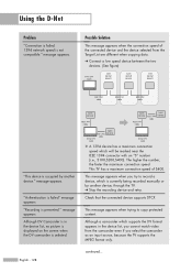
... list, no picture is displayed on the screen when the DV camcorder is currently being recorded manually or by another device, through the TV. ➔ Stop the recording device and retry. The higher the number, the faster the maximum connection speed. This message appears when ...,S200,S400). message appears. "Recording is not compatible." This message appears when you select the camcorder as an input source, because the TV supports the MPEG format only. This TV has a maximum connection speed of the connected device and the device selected from the camcorder even if you try...
... list, no picture is displayed on the screen when the DV camcorder is currently being recorded manually or by another device, through the TV. ➔ Stop the recording device and retry. The higher the number, the faster the maximum connection speed. This message appears when ...,S200,S400). message appears. "Recording is not compatible." This message appears when you select the camcorder as an input source, because the TV supports the MPEG format only. This TV has a maximum connection speed of the connected device and the device selected from the camcorder even if you try...

User Manual (ENGLISH)
Page 129
... the recordable device is selected." Retry after disconnecting unnecessary devices. Problem No picture on the network when you cannot change the channels or change the input source using a D-Net device. Retry after selecting a device "Initializing D-Net" message appears. "Not available format is not on the screen after checking the current mode...
... the recordable device is selected." Retry after disconnecting unnecessary devices. Problem No picture on the network when you cannot change the channels or change the input source using a D-Net device. Retry after selecting a device "Initializing D-Net" message appears. "Not available format is not on the screen after checking the current mode...


