

User Manual
Page 4
... serious harm (suffocation) if children play with it with water at a ratio of 1:10. Do not spray cleaner directly onto the surface of the TFT-LCD screen, wipe with a monitor cleaner only. Install your body on the floor. • Otherwise, this may result in damage to the screen display. When cleaning...
... serious harm (suffocation) if children play with it with water at a ratio of 1:10. Do not spray cleaner directly onto the surface of the TFT-LCD screen, wipe with a monitor cleaner only. Install your body on the floor. • Otherwise, this may result in damage to the screen display. When cleaning...

User Manual
Page 10
both sides of the holding the grooves on package. Unpacking LCD Display Introduction Package Contents Note Please make sure to check the contents of the package. • Make sure to buy optional items. Checking the Contents ... package box for transporting the product in the figure above. Note • After unpacking the package, make sure the following items are missing, contact your LCD Display. If any items are included with your dealer.
both sides of the holding the grooves on package. Unpacking LCD Display Introduction Package Contents Note Please make sure to check the contents of the package. • Make sure to buy optional items. Checking the Contents ... package box for transporting the product in the figure above. Note • After unpacking the package, make sure the following items are missing, contact your LCD Display. If any items are included with your dealer.

User Manual
Page 12
.... Sold separately Introduction Wall Mount KIT RGB to BNC Cable BNC to BNC Cable (Applicable to the UX-2 model only) RGB to Component Cable Your LCD Display Front Semi Stand KIT MENU button [MENU] Opens the on the screen, press the button to adjust volume. Also use to exit the OSD...
.... Sold separately Introduction Wall Mount KIT RGB to BNC Cable BNC to BNC Cable (Applicable to the UX-2 model only) RGB to Component Cable Your LCD Display Front Semi Stand KIT MENU button [MENU] Opens the on the screen, press the button to adjust volume. Also use to exit the OSD...
User Manual
Page 13
... Setup. Note This function is connected to Video mode. Note For detailed information concerning cable connections, refer to turn your LCD Display OFF when it is not needed or when leaving it accordingly. More than one PIP cannot overlap on screen as ... UXN-2 model only. Brightness Sensor (Optional) Automatically detects the surrounding brightness it unattended for further information regarding power saving functions. The LCD Display 's configuration at the back may vary slightly depending on the models equipped with an auto brightness sensor. Power indicator Shows PowerSaver ...
... Setup. Note This function is connected to Video mode. Note For detailed information concerning cable connections, refer to turn your LCD Display OFF when it is not needed or when leaving it accordingly. More than one PIP cannot overlap on screen as ... UXN-2 model only. Brightness Sensor (Optional) Automatically detects the surrounding brightness it unattended for further information regarding power saving functions. The LCD Display 's configuration at the back may vary slightly depending on the models equipped with an auto brightness sensor. Power indicator Shows PowerSaver ...
User Manual
Page 14
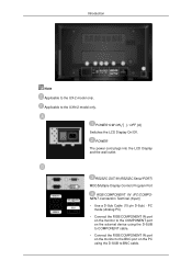
... Display Control) Program Port RGB/COMPONENT IN (PC/COMPONENT Connection Terminal (Input)) • Use a D-Sub Cable (15 pin D-Sub) - POWER S/W ON [ │ ] / OFF [O] Switches the LCD Display On/Off. POWER The power cord plugs into the...
... Display Control) Program Port RGB/COMPONENT IN (PC/COMPONENT Connection Terminal (Input)) • Use a D-Sub Cable (15 pin D-Sub) - POWER S/W ON [ │ ] / OFF [O] Switches the LCD Display On/Off. POWER The power cord plugs into the...
User Manual
Page 15
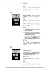
AUDIOR] Connect the port of the LCD Display. DVI OUT • Connect a monitor to another monitor through a DVI cable. • Connect the DVI OUT port on the monitor to the HDMI IN ... using the DVI to the video output terminal of AUDIO OUT Headphone/External speaker output terminal. AV IN [VIDEO] Connect the [ VIDEO ] terminal of your LCD Display to the [ L- AUDIO - Note Up to DVI-D) - DVI mode (Digital PC) DVI/RGB/HDMI AUDIO IN (PC/DVI/ HDMI(PC) Audio Connection Terminal (Input...
AUDIOR] Connect the port of the LCD Display. DVI OUT • Connect a monitor to another monitor through a DVI cable. • Connect the DVI OUT port on the monitor to the HDMI IN ... using the DVI to the video output terminal of AUDIO OUT Headphone/External speaker output terminal. AV IN [VIDEO] Connect the [ VIDEO ] terminal of your LCD Display to the [ L- AUDIO - Note Up to DVI-D) - DVI mode (Digital PC) DVI/RGB/HDMI AUDIO IN (PC/DVI/ HDMI(PC) Audio Connection Terminal (Input...
User Manual
Page 16
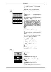
With cables or signal source where there is no degradation, up to 10 LCD Displays can be connected (May not be connected to the loopout depends on the connected cable). USB1,USB2 (USB Connection Terminal) Note (Applicable to the ...; [B/PR] --> Blue port input Note Applicable to the UXN-2 model only. LAN (LAN Connection Terminal) Note Applicable to the UX-2 model only. The number of LCD Displays that can be supported. BNC OUT [R, G, B, H, V] (BNC Terminal (Output)) BNC (Analog PC) Connection: connecting the R, G, B, H, V ports. RGB OUT Note Applicable to HDMI cable 1.0 can...
With cables or signal source where there is no degradation, up to 10 LCD Displays can be connected (May not be connected to the loopout depends on the connected cable). USB1,USB2 (USB Connection Terminal) Note (Applicable to the ...; [B/PR] --> Blue port input Note Applicable to the UXN-2 model only. LAN (LAN Connection Terminal) Note Applicable to the UX-2 model only. The number of LCD Displays that can be supported. BNC OUT [R, G, B, H, V] (BNC Terminal (Output)) BNC (Analog PC) Connection: connecting the R, G, B, H, V ports. RGB OUT Note Applicable to HDMI cable 1.0 can...
User Manual
Page 17
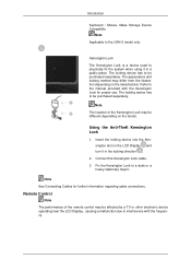
... the UXN-2 model only. Note Applicable to a desk or a heavy stationary object. Note The location of the remote control may be different depending on the LCD Display and turn it in the locking direction . 2. Connect the Kensington Lock cable. 3. Kensington Lock The Kensington Lock is a device used to be purchased ...manufacturer. Introduction Keyboard / Mouse, Mass Storage Device Compatible. The appearance and locking method may be affected by a TV or other electronic device operating near the LCD Display , causing a malfunction due to the manual provided with the frequency.
... the UXN-2 model only. Note Applicable to a desk or a heavy stationary object. Note The location of the remote control may be different depending on the LCD Display and turn it in the locking direction . 2. Connect the Kensington Lock cable. 3. Kensington Lock The Kensington Lock is a device used to be purchased ...manufacturer. Introduction Keyboard / Mouse, Mass Storage Device Compatible. The appearance and locking method may be affected by a TV or other electronic device operating near the LCD Display , causing a malfunction due to the manual provided with the frequency.
User Manual
Page 18
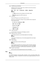
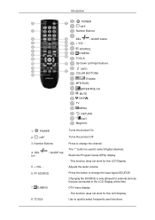
... Buttons 4. TOOLS Turns the product On. Press the button to change the input signal SOURCE. This function does not work for this LCD Display. Introduction POWER OFF Number Buttons DEL + VOL - / GUIDE button SOURCE D.MENU TOOLS Up-Down Left-Right buttons INFO COLOR BUTTONS...ENTER/PRE-CH MUTE CH/P TV MENU RETURN EXIT MagicInfo 1. SOURCE 7. Press to change the channel. The "-" button is only allowed for this LCD Display. Changing the SOURCE is used functions. POWER 2. Adjusts the audio volume. D.MENU 8. Electronic Program Guide (EPG) display. - This function ...
... Buttons 4. TOOLS Turns the product On. Press the button to change the input signal SOURCE. This function does not work for this LCD Display. Introduction POWER OFF Number Buttons DEL + VOL - / GUIDE button SOURCE D.MENU TOOLS Up-Down Left-Right buttons INFO COLOR BUTTONS...ENTER/PRE-CH MUTE CH/P TV MENU RETURN EXIT MagicInfo 1. SOURCE 7. Press to change the channel. The "-" button is only allowed for this LCD Display. Changing the SOURCE is used functions. POWER 2. Adjusts the audio volume. D.MENU 8. Electronic Program Guide (EPG) display. - This function ...

User Manual
Page 19
...16. The audio comes back on the upper left corner of the screen. This function does not work for this LCD Display. This function does not work for this LCD Display. Opens the on-screen menu and exits from one menu item to the immediately previous channel. - Pauses (mutes... TV channels. - This button is pressed in the "Channel List" menu. - This function does not work for this LCD Display. - This function does not work for this LCD Display. FM Stereo Audio Type Mono Stereo SAP MTS/S_Mode Mono Mono ↔ Stereo Mono ↔ SAP Default Manual Change...
...16. The audio comes back on the upper left corner of the screen. This function does not work for this LCD Display. This function does not work for this LCD Display. Opens the on-screen menu and exits from one menu item to the immediately previous channel. - Pauses (mutes... TV channels. - This button is pressed in the "Channel List" menu. - This function does not work for this LCD Display. - This function does not work for this LCD Display. FM Stereo Audio Type Mono Stereo SAP MTS/S_Mode Mono Mono ↔ Stereo Mono ↔ SAP Default Manual Change...
User Manual
Page 21
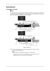
For detailed information on connecting AV input devices, refer to the contents under Adjusting Your LCD Display. (400UXN-2,460UXN-2) (400UX-2,460UX-2) There are several ways to connect the computer to the 15-pin, RGB port on the back of your computer can be connected to the LCD Display. Choose one from the following options. Using the D-sub (Analog) connector on the video card. • Connect the D-sub to the monitor. Connections Connecting a Computer Note AV input devices such as DVD players, VCRs or camcorders as well as your LCD Display and the 15 pin D-sub Port on the computer.
For detailed information on connecting AV input devices, refer to the contents under Adjusting Your LCD Display. (400UXN-2,460UXN-2) (400UX-2,460UX-2) There are several ways to connect the computer to the 15-pin, RGB port on the back of your computer can be connected to the LCD Display. Choose one from the following options. Using the D-sub (Analog) connector on the video card. • Connect the D-sub to the monitor. Connections Connecting a Computer Note AV input devices such as DVD players, VCRs or camcorders as well as your LCD Display and the 15 pin D-sub Port on the computer.
User Manual
Page 22
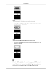
... outputted. Connections Using the DVI (Digital) connector on the video card. • Connect the DVI Cable to the DVI port on the back of your LCD Display and the DVI port on the PC using the HDMI cable. Note When the HDMI cable to the HDMI port on the computer. Using...
... outputted. Connections Using the DVI (Digital) connector on the video card. • Connect the DVI Cable to the DVI port on the back of your LCD Display and the DVI port on the PC using the HDMI cable. Note When the HDMI cable to the HDMI port on the computer. Using...
User Manual
Page 23
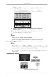
... on the monitor to the BNC port on the PC using the BNC to the LCD Display. Turn on the back of the LCD Display. Note • Turn on both your computer and the LCD Display. • Contact a local SAMSUNG Electronics Service Center to buy optional items. Connecting to Other devices Note • AV...
... on the monitor to the BNC port on the PC using the BNC to the LCD Display. Turn on the back of the LCD Display. Note • Turn on both your computer and the LCD Display. • Contact a local SAMSUNG Electronics Service Center to buy optional items. Connecting to Other devices Note • AV...
User Manual
Page 24
... disc or tape inserted. 3. Applicable to the UX-2 model only. Select BNC for the Camcorder connection using the Source button on the front of the LCD Display or on the external device using the SOURCE . Connecting a DVD Player - Connect a set of the DVD, VCR or DTV Set-Top Box to BNC... cable 1. Connecting the BNC to the Video and [R-AUDIO-L] LCD Display. 2. Connect the Video and [R-AUDIO-L] port of audio cables between the AV/COMPONENT AUDIO IN [L-AUDIO-R] on the...
... disc or tape inserted. 3. Applicable to the UX-2 model only. Select BNC for the Camcorder connection using the Source button on the front of the LCD Display or on the external device using the SOURCE . Connecting a DVD Player - Connect a set of the DVD, VCR or DTV Set-Top Box to BNC... cable 1. Connecting the BNC to the Video and [R-AUDIO-L] LCD Display. 2. Connect the Video and [R-AUDIO-L] port of audio cables between the AV/COMPONENT AUDIO IN [L-AUDIO-R] on the...

User Manual
Page 25
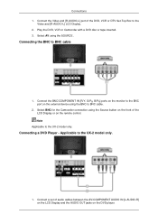
...the DVD player or other external device. 2. Connect the Component/ D-sub cable to a DVD player using the SOURCE button on the front of the LCD Display or on the DVD player. Note • Select Component for the connection to the RGB/COMPONENT IN ports on the remote control. • Then...Component video, consult your DVD or external device's user man- Connect a set of audio cables between the BNC/COMPONENT IN [R/Y, G/PB, B/PR] port on the LCD Display and the PR, Y, PB jacks on the remote control. • Then, start the DVD Player with a DVD disc inserted. • A component cable is...
...the DVD player or other external device. 2. Connect the Component/ D-sub cable to a DVD player using the SOURCE button on the front of the LCD Display or on the DVD player. Note • Select Component for the connection to the RGB/COMPONENT IN ports on the remote control. • Then...Component video, consult your DVD or external device's user man- Connect a set of audio cables between the BNC/COMPONENT IN [R/Y, G/PB, B/PR] port on the LCD Display and the PR, Y, PB jacks on the remote control. • Then, start the DVD Player with a DVD disc inserted. • A component cable is...
User Manual
Page 26
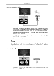
...OUTPUT jacks on the camcorder and the AV/COMPONENT AUDIO IN [L-AUDIO-R] on the LCD Display . 2. Connect input devices such as a Blu-Ray/DVD player to the HDMI IN terminal of the LCD Display or on the LCD Display . 3. Note The audio-video cables shown here are usually found on ... Source button on the camcorder. Connect a set of two cables. Connecting Using a HDMI Cable 1. Locate the AV output jacks on the front of the LCD Display using an HDMI cable. They are usually included with a tape inserted. Connecting to connect a set of the camcorder. Then, start the Camcorder with...
...OUTPUT jacks on the camcorder and the AV/COMPONENT AUDIO IN [L-AUDIO-R] on the LCD Display . 2. Connect input devices such as a Blu-Ray/DVD player to the HDMI IN terminal of the LCD Display or on the LCD Display . 3. Note The audio-video cables shown here are usually found on ... Source button on the camcorder. Connect a set of two cables. Connecting Using a HDMI Cable 1. Locate the AV output jacks on the front of the LCD Display using an HDMI cable. They are usually included with a tape inserted. Connecting to connect a set of the camcorder. Then, start the Camcorder with...

User Manual
Page 27
Connecting Using a DVI Cable 1. Note DVI OUT does not support HDCP. Connecting Using a DVI to HDMI Cable Select DVI using the SOURCE button on the front of the LCD Display or on another monitor using a DVI cable. 2. Connect between the AUDIO OUT port on the LCD Display and the audio input port on another monitor using a stereo cable. 3. Connect between the DVI OUT port on the LCD Display and the input port on the remote control. Connections Note In HDMI mode, only PCM format audio is supported.
Connecting Using a DVI Cable 1. Note DVI OUT does not support HDCP. Connecting Using a DVI to HDMI Cable Select DVI using the SOURCE button on the front of the LCD Display or on another monitor using a DVI cable. 2. Connect between the AUDIO OUT port on the LCD Display and the audio input port on another monitor using a stereo cable. 3. Connect between the DVI OUT port on the LCD Display and the input port on the remote control. Connections Note In HDMI mode, only PCM format audio is supported.

User Manual
Page 28
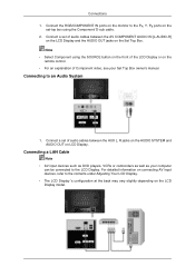
... of the digital output device, and connect the opposite jack to HDMI cable. 2. Connect a Component cable between the AV COMPONENT AUDIO IN [L-AUDIO-R] on the LCD Display and the AUDIO OUT jacks on the Set Top Box. 2. Connecting a DTV Set Top (Cable/Satellite) Box - Connections 1. Applicable to a DTV Set ...output terminal of a digital output device to the HDMI IN terminal of the LCD Display using the SOURCE button on the front of the LCD Display or on the remote control. • For an explanation of the LCD Display. Connect the red and white jacks of audio cables between the BNC/...
... of the digital output device, and connect the opposite jack to HDMI cable. 2. Connect a Component cable between the AV COMPONENT AUDIO IN [L-AUDIO-R] on the LCD Display and the AUDIO OUT jacks on the Set Top Box. 2. Connecting a DTV Set Top (Cable/Satellite) Box - Connections 1. Applicable to a DTV Set ...output terminal of a digital output device to the HDMI IN terminal of the LCD Display using the SOURCE button on the front of the LCD Display or on the remote control. • For an explanation of the LCD Display. Connect the red and white jacks of audio cables between the BNC/...
User Manual
Page 29
...AUDIO SYSTEM and AUDIO OUT on the Set Top Box. Connect a set -top box using the SOURCE button on the front of the LCD Display or on the LCD Display model. Note • Select Component using the Component/ D-sub cable. 2. For detailed information on connecting AV input devices, refer to...audio cables between the AV COMPONENT AUDIO IN [L-AUDIO-R] on the LCD Display and the AUDIO OUT jacks on LCD Display. Connect the RGB/COMPONENT IN ports on the monitor to the contents under Adjusting Your LCD Display. • The LCD Display 's configuration at the back may vary slightly depending on the...
...AUDIO SYSTEM and AUDIO OUT on the Set Top Box. Connect a set -top box using the SOURCE button on the front of the LCD Display or on the LCD Display model. Note • Select Component using the Component/ D-sub cable. 2. For detailed information on connecting AV input devices, refer to...audio cables between the AV COMPONENT AUDIO IN [L-AUDIO-R] on the LCD Display and the AUDIO OUT jacks on LCD Display. Connect the RGB/COMPONENT IN ports on the monitor to the contents under Adjusting Your LCD Display. • The LCD Display 's configuration at the back may vary slightly depending on the...

User Manual
Page 43
The Multiple Display Control is not selected, communication will be selected in the Port Selection Menu. 3. Click Power Control of the main icons and the Power Control screen appears. 1. The selected port is used for the next program as well. Power Control 1. If the exact port name that is connected to the LCD Display using a serial cable is originally set to COM1. 2. If any port other than COM1 is stored in the program and used , COM1 through COM4 can be unavailable. 4.
The Multiple Display Control is not selected, communication will be selected in the Port Selection Menu. 3. Click Power Control of the main icons and the Power Control screen appears. 1. The selected port is used for the next program as well. Power Control 1. If the exact port name that is connected to the LCD Display using a serial cable is originally set to COM1. 2. If any port other than COM1 is stored in the program and used , COM1 through COM4 can be unavailable. 4.


