
User Manual
Page 1
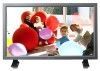
All rights reserved. SyncMaster 320PX Install Programs PDF Manuals Registration Model Select Language Safety Instructions Introduction Connections Using the Software Adjusting the LCD Display Troubleshooting Specifications Information Appendix © 2006 Samsung Electronics Co., Ltd.
All rights reserved. SyncMaster 320PX Install Programs PDF Manuals Registration Model Select Language Safety Instructions Introduction Connections Using the Software Adjusting the LCD Display Troubleshooting Specifications Information Appendix © 2006 Samsung Electronics Co., Ltd.
User Manual
Page 2
Select Language Main Page Safety Instructions Notational Power Installation Clean Others Introduction Connections Using the Software Adjusting the LCD Display Troubleshooting Specifications Information Appendix Model SyncMaster 320PX The color and appearance of the product may vary depending on the model, and the product specifications are designed to prevent damage to property and ...
Select Language Main Page Safety Instructions Notational Power Installation Clean Others Introduction Connections Using the Software Adjusting the LCD Display Troubleshooting Specifications Information Appendix Model SyncMaster 320PX The color and appearance of the product may vary depending on the model, and the product specifications are designed to prevent damage to property and ...
User Manual
Page 3
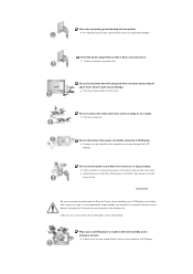
... shock or fire inside the LCD Display. Ins tall ati on Be sure to do so may cause electric shock or equipment damage. Do not connect too many extension cords or plugs to your LCD Display in a location with a dusty plug or connector may damage the LCD Display. z Failure to... a location with a dry cloth. Insert the power plug firmly so that it with low humidity and a minimum of the power cord is dusty. z A bad connection may cause fire. z Using the power cord with heavy dust, high or low temperatures, high humidity, and exposed to do so may cause electric shock...
... shock or fire inside the LCD Display. Ins tall ati on Be sure to do so may cause electric shock or equipment damage. Do not connect too many extension cords or plugs to your LCD Display in a location with a dusty plug or connector may damage the LCD Display. z Failure to... a location with a dry cloth. Insert the power plug firmly so that it with low humidity and a minimum of the power cord is dusty. z A bad connection may cause fire. z Using the power cord with heavy dust, high or low temperatures, high humidity, and exposed to do so may cause electric shock...
User Manual
Page 8
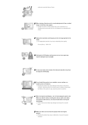
... the mode to energy saving mode or set a screensaver to the person carrying it. Make sure that all cables, including the antenna cable and cables connected to other devices, are more than two people when moving the LCD Display , turn off and unplug the power cord. z Dropping the product may damage...
... the mode to energy saving mode or set a screensaver to the person carrying it. Make sure that all cables, including the antenna cable and cables connected to other devices, are more than two people when moving the LCD Display , turn off and unplug the power cord. z Dropping the product may damage...

User Manual
Page 11
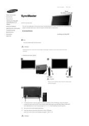
... Power Cord Speaker Wire Cable Select Language Main Page Safety Instructions Introduction Package Contents Your LCD Display Machanical Layout Connections Using the Software Adjusting the LCD Display Troubleshooting Specifications Information Appendix Model SyncMaster 320PX The color and appearance of performance enhancement. Introduction Package Contents Note • Please make sure the following items...
... Power Cord Speaker Wire Cable Select Language Main Page Safety Instructions Introduction Package Contents Your LCD Display Machanical Layout Connections Using the Software Adjusting the LCD Display Troubleshooting Specifications Information Appendix Model SyncMaster 320PX The color and appearance of performance enhancement. Introduction Package Contents Note • Please make sure the following items...

User Manual
Page 13
... for long periods. For energy conservation, turn the PIP screen On / Off. Rear Note • For detailed information concerning cable connections, refer to Video mode. More than one PIP cannot overlap on screen as BNC and the component use the same terminal. >>... when it unattended for further information regarding power saving functions. Adjusts the audio volume. 4) ENTER Activates a highlighted menu item. 5) SOURCE Switches from PC mode to Connecting Cables under Setup. The LCD Display 's configuration at the time. [PC] → [BNC] → [DVI] → [AV] → [S-Video]...
... for long periods. For energy conservation, turn the PIP screen On / Off. Rear Note • For detailed information concerning cable connections, refer to Video mode. More than one PIP cannot overlap on screen as BNC and the component use the same terminal. >>... when it unattended for further information regarding power saving functions. Adjusts the audio volume. 4) ENTER Activates a highlighted menu item. 5) SOURCE Switches from PC mode to Connecting Cables under Setup. The LCD Display 's configuration at the time. [PC] → [BNC] → [DVI] → [AV] → [S-Video]...
User Manual
Page 14
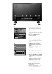
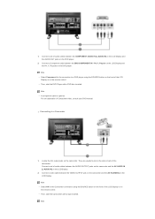
.../DVI/BNC AUDIO IN] (PC/DVI/BNC Audio Connection Terminal (Input)) 5) COMPONENT AUDIO IN [L -AUDIO-R] (Component Audio Connection Terminal (Input)) 6) BNC/COMPONENT OUT [R/PR, G/Y, B/PB, H, V] (BNC/Component Connection Terminal (Output)) BNC (Analog PC) Connection: connecting the R, G, B, H, V ports Component Connection: connecting the P R, Y, PB ports 7) BNC/COMPONENT IN [R/PR, G/Y, B/P B, H, V] (BNC/Component Connection Terminal (Input)) 8) AV AUDIO IN [L -AUDIO-R] (LCD Display...
.../DVI/BNC AUDIO IN] (PC/DVI/BNC Audio Connection Terminal (Input)) 5) COMPONENT AUDIO IN [L -AUDIO-R] (Component Audio Connection Terminal (Input)) 6) BNC/COMPONENT OUT [R/PR, G/Y, B/PB, H, V] (BNC/Component Connection Terminal (Output)) BNC (Analog PC) Connection: connecting the R, G, B, H, V ports Component Connection: connecting the P R, Y, PB ports 7) BNC/COMPONENT IN [R/PR, G/Y, B/P B, H, V] (BNC/Component Connection Terminal (Input)) 8) AV AUDIO IN [L -AUDIO-R] (LCD Display...
User Manual
Page 15
....) For using a locking device, contact the place of purchase. • See Connecting the LCD Display for sound output of the remote control may be connected to be connected. 17) Kensington Lock Note The Kensington lock is the terminal for further information regarding... cable connections. LOCK 5. P.MO DE 13. MAGICNET 3. MagicNet buttons 6.+100 -/-- 7. MENU 11. PRE-CH 15 . EXIT R - +] (EXT Speaker Connection Terminal) 14) AUDIO OUT [L -AUDIO-R] (LCD Display Audio Connection Terminal (Output)) AUDIO OUT is a device...
....) For using a locking device, contact the place of purchase. • See Connecting the LCD Display for sound output of the remote control may be connected to be connected. 17) Kensington Lock Note The Kensington lock is the terminal for further information regarding... cable connections. LOCK 5. P.MO DE 13. MAGICNET 3. MagicNet buttons 6.+100 -/-- 7. MENU 11. PRE-CH 15 . EXIT R - +] (EXT Speaker Connection Terminal) 14) AUDIO OUT [L -AUDIO-R] (LCD Display Audio Connection Terminal (Output)) AUDIO OUT is a device...
User Manual
Page 21
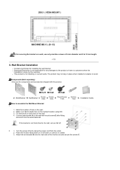
... done by the customer. Mark the location of 6 mm diameter and 8 to 12 mm length. 6. Fix anchors F on each hole on plaster or wood. Connect wall-bracket A to assemble the Wall Mount Bracket 1 1. Attach the set-bracket B onto the rear side of the monitor set can fall off and unplug... the power cord from the outlet. 2. The product may not stay in place when installed on the wall. 4. z Samsung Electronics is not responsible for any damages to the product or harm to the wall, set and secure the screws C. Turn the power off . 2 1....
... done by the customer. Mark the location of 6 mm diameter and 8 to 12 mm length. 6. Fix anchors F on each hole on plaster or wood. Connect wall-bracket A to assemble the Wall Mount Bracket 1 1. Attach the set-bracket B onto the rear side of the monitor set can fall off and unplug... the power cord from the outlet. 2. The product may not stay in place when installed on the wall. 4. z Samsung Electronics is not responsible for any damages to the product or harm to the wall, set and secure the screws C. Turn the power off . 2 1....

User Manual
Page 22
3 1. Before installing the set on the wall, connect the cables to the set -bracket B and wall-bracket A with screws D. Fix set first. Insert three Hangers of the set-bracket B into the grooves of the wall-bracket A. 2.
3 1. Before installing the set on the wall, connect the cables to the set -bracket B and wall-bracket A with screws D. Fix set first. Insert three Hangers of the set-bracket B into the grooves of the wall-bracket A. 2.
User Manual
Page 23
...and cover the hole using a base other than those specified. Connections Installing the Stand KIT Note • Only the supplied bolts should be responsible for reasons of performance enhancement. Caution Samsung Electronics will not be used to protect the hole at the ...the LCD Display. Select Language Main Page Safety Instructions Introduction Connections Installing the Stand KIT Connecting the LCD Display Using the Software Adjusting the LCD Display Troubleshooting Specifications Information Appendix Model SyncMaster 320PX The color and appearance of the product may vary depending ...
...and cover the hole using a base other than those specified. Connections Installing the Stand KIT Note • Only the supplied bolts should be responsible for reasons of performance enhancement. Caution Samsung Electronics will not be used to protect the hole at the ...the LCD Display. Select Language Main Page Safety Instructions Introduction Connections Installing the Stand KIT Connecting the LCD Display Using the Software Adjusting the LCD Display Troubleshooting Specifications Information Appendix Model SyncMaster 320PX The color and appearance of the product may vary depending ...

User Manual
Page 24
...disconnect the AC power in the right place. (M4 x L15) 3) Insert the stand into the hole indicated and tighten it. (M4 x L15) Connecting the LCD Display Using a Power cord with Earth In the event of the LCD Display , where the stand is inserted. For detailed information on . This... stand is designed for placing something on connecting AV input devices, refer to the User Controls under Adjusting Your LCD Display. Connecting to the LCD Display. The company is not responsible for any problem caused when using the 'Cover-...
...disconnect the AC power in the right place. (M4 x L15) 3) Insert the stand into the hole indicated and tighten it. (M4 x L15) Connecting the LCD Display Using a Power cord with Earth In the event of the LCD Display , where the stand is inserted. For detailed information on . This... stand is designed for placing something on connecting AV input devices, refer to the User Controls under Adjusting Your LCD Display. Connecting to the LCD Display. The company is not responsible for any problem caused when using the 'Cover-...

User Manual
Page 25
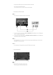
... audio cable for your computer. Note • The DVI cable or BNC cable is optional. Contact a local Samsung Electronics Service Center to the BNC/COMPONENT IN - Connect the BNC Cable to buy optional items. Note • Turn on the video card. Choose one of your LCD Display and the DVI port on... the BNC (Analog) connector on both your computer and the LCD Display. Trun on the video card. R, G, B, H, V ports on the back of the LCD Display. Connect the D -sub to the 15-pin, RGB port on the back of your LCD Display and the 15 pin D sub Port on the computer. 2-2) Using...
... audio cable for your computer. Note • The DVI cable or BNC cable is optional. Contact a local Samsung Electronics Service Center to the BNC/COMPONENT IN - Connect the BNC Cable to buy optional items. Note • Turn on the video card. Choose one of your LCD Display and the DVI port on... the BNC (Analog) connector on both your computer and the LCD Display. Trun on the video card. R, G, B, H, V ports on the back of the LCD Display. Connect the D -sub to the 15-pin, RGB port on the back of your LCD Display and the 15 pin D sub Port on the computer. 2-2) Using...

User Manual
Page 26
.... Note • The monitor has DVI IN connection terminals to the LCD Display 's AV AUDIO IN [L-AUDIO -R] using an S-VHS or BNC cable. 2) Connect the Audio (L) and Audio (R) terminals of a VCR or Camcorders to connect DVI input devices digital DVD. Connecting to a VCR 1) AV input devices such as... digital DVD are connected via the AV IN [VIDEO] or AV IN [S -VIDEO] of the...
.... Note • The monitor has DVI IN connection terminals to the LCD Display 's AV AUDIO IN [L-AUDIO -R] using an S-VHS or BNC cable. 2) Connect the Audio (L) and Audio (R) terminals of a VCR or Camcorders to connect DVI input devices digital DVD. Connecting to a VCR 1) AV input devices such as... digital DVD are connected via the AV IN [VIDEO] or AV IN [S -VIDEO] of the...
User Manual
Page 27
... optional. For an explanation of audio cables between the AUDIO OUTPUT jacks on the camcorder and the AV AUDIO IN [L-AUDIO-R] on the LCD Display. 2) Connect a video cable between the BNC/COMPONENT IN - Note PR, Y, PB port on the LCD Display and the PR, Y, PB jacks on the camcorder... of the LCD Display or on the remote control. • Then, start the DVD Player with a tape inserted. Connecting to a DVD player using the SOURCE button on the LCD Display. They are usually found on the side or back of the LCD Display or ...
... optional. For an explanation of audio cables between the AUDIO OUTPUT jacks on the camcorder and the AV AUDIO IN [L-AUDIO-R] on the LCD Display. 2) Connect a video cable between the BNC/COMPONENT IN - Note PR, Y, PB port on the LCD Display and the PR, Y, PB jacks on the camcorder... of the LCD Display or on the remote control. • Then, start the DVD Player with a tape inserted. Connecting to a DVD player using the SOURCE button on the LCD Display. They are usually found on the side or back of the LCD Display or ...
User Manual
Page 28
... the SET and the speaker using the SOURCE button on the front of two cables. • The audio-video cables shown here are shown below. 1) Connect a Component cable between the COMPONENT AUDIO IN [L-AUDIO-R] on the LCD Display and the AUDIO OUT jacks on the Set Top Box. Note • For... store.) If your Set Top Box owner's manual. PR, Y, PB port on the LCD Display and the PR, Y, PB jacks on the Set Top Box. 2) Connect a set of Component video, see your camcorder is stereo, you need to a DTV Set Top Box using the screws. * Mount the speaker set of the...
... the SET and the speaker using the SOURCE button on the front of two cables. • The audio-video cables shown here are shown below. 1) Connect a Component cable between the COMPONENT AUDIO IN [L-AUDIO-R] on the LCD Display and the AUDIO OUT jacks on the Set Top Box. Note • For... store.) If your Set Top Box owner's manual. PR, Y, PB port on the LCD Display and the PR, Y, PB jacks on the Set Top Box. 2) Connect a set of Component video, see your camcorder is stereo, you need to a DTV Set Top Box using the screws. * Mount the speaker set of the...

User Manual
Page 29
ALL Rights Reserved Connecting to the speakers. Note • Do not move the SET while the SET is connected to an Audio System Note • Connect a set of the speaker. Note • Connect the speaker connection cable between the speaker connection jack on the back of the SET and the speaker connection jack on the back of audio cables between the AUX L, R jacks on the AUDIO SYSTEM and the AUDIO OUT [L-AUDIO-R] on LCD Display. © 1995~2007 SAMSUNG. The speaker-bracket for connecting the SET speaker my become damaged.
ALL Rights Reserved Connecting to the speakers. Note • Do not move the SET while the SET is connected to an Audio System Note • Connect a set of the speaker. Note • Connect the speaker connection cable between the speaker connection jack on the back of the SET and the speaker connection jack on the back of audio cables between the AUX L, R jacks on the AUDIO SYSTEM and the AUDIO OUT [L-AUDIO-R] on LCD Display. © 1995~2007 SAMSUNG. The speaker-bracket for connecting the SET speaker my become damaged.

User Manual
Page 30
Introduction A Multiple Display Control (MDC) is used for the communication between the serial port on a PC and the serial port on a PC. Therefore, a serial cable should be easily and simultaneously operated on a display. Main Screen Click Start > Program > Samsung > MDC System to see the volume of serial communication, is an application allowing various displays to be connected between a PC and a display. RS-232C, a standard of the selected set within the slider. Select a set to start the program.
Introduction A Multiple Display Control (MDC) is used for the communication between the serial port on a PC and the serial port on a PC. Therefore, a serial cable should be easily and simultaneously operated on a display. Main Screen Click Start > Program > Samsung > MDC System to see the volume of serial communication, is an application allowing various displays to be connected between a PC and a display. RS-232C, a standard of the selected set within the slider. Select a set to start the program.

User Manual
Page 31
... Control Tools to switch into each screen. 2. Use the main icons to control displays. Click Select all or Clear to select or clear all displays connected to Enable when the MDC is COM1. 5. Main Icons Remocon Safety Lock Port Selection Select Button Info Grid Display Selection Control Tools 1. Set the Safety...
... Control Tools to switch into each screen. 2. Use the main icons to control displays. Click Select all or Clear to select or clear all displays connected to Enable when the MDC is COM1. 5. Main Icons Remocon Safety Lock Port Selection Select Button Info Grid Display Selection Control Tools 1. Set the Safety...

User Manual
Page 32
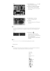
Power Control 1. If any port other than COM1 is stored in the Port Selection Menu. 3. Click Power Control of the main icons and the Power Control screen appears. The selected port is used for the next program as well. 1. The Multiple Display Control is not selected, communication will be selected in the program and used , COM1 through COM4 can be unavailable. 4. If the exact port name that is connected to the LCD Display using a serial cable is originally set to COM1. 2.
Power Control 1. If any port other than COM1 is stored in the Port Selection Menu. 3. Click Power Control of the main icons and the Power Control screen appears. The selected port is used for the next program as well. 1. The Multiple Display Control is not selected, communication will be selected in the program and used , COM1 through COM4 can be unavailable. 4. If the exact port name that is connected to the LCD Display using a serial cable is originally set to COM1. 2.

