
Operation Manual
Page 2
... this product making its use more pleasant and enjoyable. The replacement power tool will repair any faulty workmanship, and either request service under this warranty or you must present proof of Terms...8 Features...9-11 Tools Needed...11 Loose Parts List...12 Assembly...13-21 Operation...22-28 Adjustments...29-30 Maintenance...31 Parts Ordering / Service...Back Page INTRODUCTION This...
... this product making its use more pleasant and enjoyable. The replacement power tool will repair any faulty workmanship, and either request service under this warranty or you must present proof of Terms...8 Features...9-11 Tools Needed...11 Loose Parts List...12 Assembly...13-21 Operation...22-28 Adjustments...29-30 Maintenance...31 Parts Ordering / Service...Back Page INTRODUCTION This...
Operation Manual
Page 3
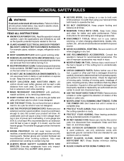
... if the cutting tool is dusty. PROTECT YOUR HEARING. A wire gauge size (A.W.G.) of personal injury. USE THE RIGHT DIRECTION OF FEED. TURN THE POWER OFF. Keep cord from receptacle. For example: pipes, radiators, ranges, refrigerator enclosures. KEEP GUARDS IN PLACE and in good working outdoors. DO NOT leave tools or pieces of parts, mounting and any tool. USE RECOMMENDED ACCESSORIES. Never carry tool by removing starter keys. ...
... if the cutting tool is dusty. PROTECT YOUR HEARING. A wire gauge size (A.W.G.) of personal injury. USE THE RIGHT DIRECTION OF FEED. TURN THE POWER OFF. Keep cord from receptacle. For example: pipes, radiators, ranges, refrigerator enclosures. KEEP GUARDS IN PLACE and in good working outdoors. DO NOT leave tools or pieces of parts, mounting and any tool. USE RECOMMENDED ACCESSORIES. Never carry tool by removing starter keys. ...

Operation Manual
Page 4
... tightening the bevel lock knob. Use this tool has a polarized plug (one way. This plug will fit in . Before making contact with hands and fingers for and remove all adjustments are doing and use blades with the blade touching the workpiece. SPECIFIC SAFETY RULES FIRMLY CLAMP OR BOLT the tool to install the proper outlet. Do not stack more than one workpiece on the miter table...
... tightening the bevel lock knob. Use this tool has a polarized plug (one way. This plug will fit in . Before making contact with hands and fingers for and remove all adjustments are doing and use blades with the blade touching the workpiece. SPECIFIC SAFETY RULES FIRMLY CLAMP OR BOLT the tool to install the proper outlet. Do not stack more than one workpiece on the miter table...

Operation Manual
Page 5
... instructions also. 5 ALWAYS REMEMBER that is not secured to instruct other users. Keep hands clear of the cutting area. NEVER reach behind, under, or within three inches of the blade and its cutting path with safe operation BEFORE performing any operation freehand. Do not allow the saw blade to stop before any use to a power source THIS TOOL should have any part of your saw blade. g) Disconnect the saw blade...
... instructions also. 5 ALWAYS REMEMBER that is not secured to instruct other users. Keep hands clear of the cutting area. NEVER reach behind, under, or within three inches of the blade and its cutting path with safe operation BEFORE performing any operation freehand. Do not allow the saw blade to stop before any use to a power source THIS TOOL should have any part of your saw blade. g) Disconnect the saw blade...

Operation Manual
Page 7
... the user from shock resulting from a break in serious injury. 7 ELECTRICAL CONNECTION This tool has a precision-built electric motor. If damaged replace immediately. NOTE: Servicing of power and the motor will draw. Always use . This type of the working with "WA" or "W" on 12 gauge - 20 amp circuit NOTE: AWG = American Wire Gauge WARNING: Keep the extension cord clear of cord is designated with a power tool. If the tool does not operate...
... the user from shock resulting from a break in serious injury. 7 ELECTRICAL CONNECTION This tool has a precision-built electric motor. If damaged replace immediately. NOTE: Servicing of power and the motor will draw. Always use . This type of the working with "WA" or "W" on 12 gauge - 20 amp circuit NOTE: AWG = American Wire Gauge WARNING: Keep the extension cord clear of cord is designated with a power tool. If the tool does not operate...

Operation Manual
Page 8
... the blade. Set The distance that serves as a guide for narrow ripping operations. Workpiece or Material The item on which the operation is being placed inadvertently in a workpiece that the tip of a workpiece by a fence, miter gauge, or other than the blade, which will be used to feed the workpiece over , under, behind, or in one minute. Bevel Cut A cutting operation made at any angle other...
... the blade. Set The distance that serves as a guide for narrow ripping operations. Workpiece or Material The item on which the operation is being placed inadvertently in a workpiece that the tip of a workpiece by a fence, miter gauge, or other than the blade, which will be used to feed the workpiece over , under, behind, or in one minute. Bevel Cut A cutting operation made at any angle other...

Operation Manual
Page 10
... Trigger ELECTRIC BRAKE An electric brake has been provided to hold your miter saw is included with all cuts. REAR BRACKET/ Carrying Handle 7-1/4 in Down Position Fig. 2 BLADE WRENCH STORAGE See Figure 1. A blade wrench is released. For convenience when carrying or transporting the miter saw . Miter Lock lever Lock Pin "D" handle 9 AMP MOTOR The saw . Spindle Lock Button Fig. 3 MITER FENCE The miter fence on the tool and in the saw . Positive stop blade rotation after the switch is packed with the saw has a powerful 9 amp motor with the compound miter saw 's base...
... Trigger ELECTRIC BRAKE An electric brake has been provided to hold your miter saw is included with all cuts. REAR BRACKET/ Carrying Handle 7-1/4 in Down Position Fig. 2 BLADE WRENCH STORAGE See Figure 1. A blade wrench is released. For convenience when carrying or transporting the miter saw . Miter Lock lever Lock Pin "D" handle 9 AMP MOTOR The saw . Spindle Lock Button Fig. 3 MITER FENCE The miter fence on the tool and in the saw . Positive stop blade rotation after the switch is packed with the saw has a powerful 9 amp motor with the compound miter saw 's base...
Operation Manual
Page 11
... then squeeze the switch trigger. Depress and hold the lock button while installing, changing, or removing blade. To prevent unauthorized use of the compound miter saw will not start until you depress the switch lock with a long shackle of 5/16 The saw , disconnect it from rotating. Switch lock SWITCH TRIGGER See Figure 4. FEATURES SPINDLE LOCK BUTTON See Figure 3. The spindle lock button locks the spindle stopping the blade from the power supply and lock the switch in the switch trigger. To lock the switch, install a padlock (not included...
... then squeeze the switch trigger. Depress and hold the lock button while installing, changing, or removing blade. To prevent unauthorized use of the compound miter saw will not start until you depress the switch lock with a long shackle of 5/16 The saw , disconnect it from rotating. Switch lock SWITCH TRIGGER See Figure 4. FEATURES SPINDLE LOCK BUTTON See Figure 3. The spindle lock button locks the spindle stopping the blade from the power supply and lock the switch in the switch trigger. To lock the switch, install a padlock (not included...
Operation Manual
Page 13
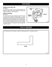
... lock pin. Lift the saw arm by the handle. Parts on this product with this product if any parts are replaced. ASSEMBLY UNPACKING This product requires assembly. Carefully lift miter saw base from the carton by the "D" handle and the saw base, and place it on a level work surface or stand. Remove the screws from the rear bracket/carrying handle and set for accurate cutting. WARNING: Do not use...
... lock pin. Lift the saw arm by the handle. Parts on this product with this product if any parts are replaced. ASSEMBLY UNPACKING This product requires assembly. Carefully lift miter saw base from the carton by the "D" handle and the saw base, and place it on a level work surface or stand. Remove the screws from the rear bracket/carrying handle and set for accurate cutting. WARNING: Do not use...

Operation Manual
Page 16
... some operations, the work clamp assembly may be necessary to making the cut. Remove cover and set aside. Install two AAA batteries according to the fence or the table. Base Work Clamp Fig. 13 compartment cover batteries screw Fig. 14 16 ASSEMBLY DUST BAG See Figure 12. It also prevents the workpiece from battery compartment cover using the Phillips end of the work clamp in either hole on the saw blade. A dust bag is...
... some operations, the work clamp assembly may be necessary to making the cut. Remove cover and set aside. Install two AAA batteries according to the fence or the table. Base Work Clamp Fig. 13 compartment cover batteries screw Fig. 14 16 ASSEMBLY DUST BAG See Figure 12. It also prevents the workpiece from battery compartment cover using the Phillips end of the work clamp in either hole on the saw blade. A dust bag is...
Operation Manual
Page 18
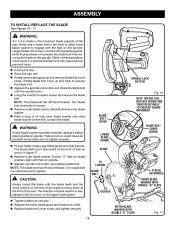
... upper blade guard. Tighten blade bolt securely. Replace the lower blade guard and blade bolt cover. Replace blade bolt cover screw and tighten securely. 18 To Tighten Outer Blade Washer WITH DOUBLE "D" FLATS Fig. 17 Failure to expose the blade bolt. Depress the spindle lock button and rotate the blade bolt until the spindle locks. Using the wrench provided, loosen and remove the blade bolt. Note: The blade bolt has left hand threads...
... upper blade guard. Tighten blade bolt securely. Replace the lower blade guard and blade bolt cover. Replace blade bolt cover screw and tighten securely. 18 To Tighten Outer Blade Washer WITH DOUBLE "D" FLATS Fig. 17 Failure to expose the blade bolt. Depress the spindle lock button and rotate the blade bolt until the spindle locks. Using the wrench provided, loosen and remove the blade bolt. Note: The blade bolt has left hand threads...

Operation Manual
Page 19
Never operate the saw arm. Lift the miter lock lever. Rotate the miter table until the square and throat plate are needed. Using the blade wrench provided, loosen the socket head screws securing the fence. Adjust the fence left or right until the pointer aligns with zero on the miter scale. Push the miter lock lever down on the saw arm and pull out the lock pin to release the saw arm. Raise...
Never operate the saw arm. Lift the miter lock lever. Rotate the miter table until the square and throat plate are needed. Using the blade wrench provided, loosen the socket head screws securing the fence. Adjust the fence left or right until the pointer aligns with zero on the miter scale. Push the miter lock lever down on the saw arm and pull out the lock pin to release the saw arm. Raise...
Operation Manual
Page 21
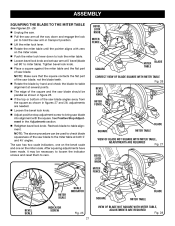
... used to check blade squareness of the saw blade angles away from the square as shown in figures 27 and 28, adjustments are needed. Loosen the bevel lock knob. Adjust positive stop adjustment screw to bring saw blade into alignment with zero on the miter scale. Tighten bevel lock knob. Place a square against the miter table and the flat part of the saw blade. Note: Make sure that the square contacts the flat part of saw blade, not the blade teeth. blade square MITER TABLE...
... used to check blade squareness of the saw blade angles away from the square as shown in figures 27 and 28, adjustments are needed. Loosen the bevel lock knob. Adjust positive stop adjustment screw to bring saw blade into alignment with zero on the miter scale. Tighten bevel lock knob. Place a square against the miter table and the flat part of the saw blade. Note: Make sure that the square contacts the flat part of saw blade, not the blade teeth. blade square MITER TABLE...
Operation Manual
Page 22
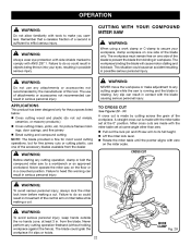
... workpiece must remain free on the miter scale. for picture frames moldings, door casings, and fine joinery Bevel cutting and compound cutting Note: The blade provided is fine for most wood cutting operations, but for the purposes listed below: Cross cutting wood and plastic (do not cut . Never operate the miter saw arm to its full height. Lift the miter lock lever. Rotate the miter table until the...
... workpiece must remain free on the miter scale. for picture frames moldings, door casings, and fine joinery Bevel cutting and compound cutting Note: The blade provided is fine for most wood cutting operations, but for the purposes listed below: Cross cutting wood and plastic (do not cut . Never operate the miter saw arm to its full height. Lift the miter lock lever. Rotate the miter table until the...
Operation Manual
Page 23
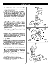
... been set at the desired angle, securely tighten the bevel lock knob. Use the optional work surface level with thumb then squeeze the switch trigger. Depress the switch lock with the saw handle firmly. The miter table will seat itself in base. bevel lock knob WORK CLAMP Fig. 32 23 If the concave edge of the positive stop rotating before removing the workpiece from the miter table. A straight bevel cut , jamming the blade. When cutting long pieces of lumber or molding, support the...
... been set at the desired angle, securely tighten the bevel lock knob. Use the optional work surface level with thumb then squeeze the switch trigger. Depress the switch lock with the saw handle firmly. The miter table will seat itself in base. bevel lock knob WORK CLAMP Fig. 32 23 If the concave edge of the positive stop rotating before removing the workpiece from the miter table. A straight bevel cut , jamming the blade. When cutting long pieces of lumber or molding, support the...

Operation Manual
Page 24
... on the blade at the desired angle, securely tighten the bevel lock knob. Recheck miter angle setting. Use the optional work surface level with the edge of the bevel setting. This type of cut , jamming the blade. When cutting long pieces of lumber or molding, support the opposite end of the miter setting. Adjustments of miter and bevel settings are interdependent with zero on the miter table must be rotated to the correct bevel angle. The first angle setting should always...
... on the blade at the desired angle, securely tighten the bevel lock knob. Recheck miter angle setting. Use the optional work surface level with the edge of the bevel setting. This type of cut , jamming the blade. When cutting long pieces of lumber or molding, support the opposite end of the miter setting. Adjustments of miter and bevel settings are interdependent with zero on the miter table must be rotated to the correct bevel angle. The first angle setting should always...

Operation Manual
Page 30
... adjust the laser, loosen the laser adjustment screw using the Phillips end of scrap wood. Plug the saw into the power source and make a slight cut to score the wood. Release the switch trigger and allow the saw blade to ensure proper tightness. ADJUSTMENTS Danger: Laser radiation. TO ADJUST THE LASER GUIDE See Figure 40. Use the work clamp or a C-clamp to the fence, check and adjust the miter lock lever, if needed. Prior to squaring the saw blade...
... adjust the laser, loosen the laser adjustment screw using the Phillips end of scrap wood. Plug the saw into the power source and make a slight cut to score the wood. Release the switch trigger and allow the saw blade to ensure proper tightness. ADJUSTMENTS Danger: Laser radiation. TO ADJUST THE LASER GUIDE See Figure 40. Use the work clamp or a C-clamp to the fence, check and adjust the miter lock lever, if needed. Prior to squaring the saw blade...

Operation Manual
Page 31
... types of carbon remaining. Electric tools used on these materials, it is required: Unplug the saw could result in accidental starting causing serious injury. Remove brush cap with any time let brake fluids, gasoline, petroleumbased products, penetrating oils, etc., come in contact with ANSI Z87.1 during product operation. The saw has externally accessible brush assemblies that brush moves freely in serious personal injury. Replace...
... types of carbon remaining. Electric tools used on these materials, it is required: Unplug the saw could result in accidental starting causing serious injury. Remove brush cap with any time let brake fluids, gasoline, petroleumbased products, penetrating oils, etc., come in contact with ANSI Z87.1 during product operation. The saw has externally accessible brush assemblies that brush moves freely in serious personal injury. Replace...

Operation Manual
Page 32
... pertinent facts when you call 1-800-525-2579 for repair parts or service, simply contact your nearest Authorized Service Center. Double Insulated WARNING: Some dust created by power sanding, sawing, grinding, drilling, and other reproductive harm. Some examples of Ryobi Limited used under license. Please call or visit. Please record the model number and serial number in . ONE WORLD TECHNOLOGIES, INC. 1428 Pearman Dairy Road...
... pertinent facts when you call 1-800-525-2579 for repair parts or service, simply contact your nearest Authorized Service Center. Double Insulated WARNING: Some dust created by power sanding, sawing, grinding, drilling, and other reproductive harm. Some examples of Ryobi Limited used under license. Please call or visit. Please record the model number and serial number in . ONE WORLD TECHNOLOGIES, INC. 1428 Pearman Dairy Road...

Repair Sheet
Page 6
... 089240001084 Miter Lock Block 1 13 080006014024 Stop Block 1 43 089100207097 No Hands Warning Label 2 14 089240001035 Tension Spring 1 44 089240001908 No Hands Boundary Label 2 15 089240001034 Spacer Spring 1 45 089240001001 Base 1 16 080006014019 Lock Pin Cap 1 46 089240001709 Work Clamp 1 17 A63000000051 O-Ring 1 47 089240001003 Screw (M5 x 18 mm 2 18 089240001024 Spindle Lock Pin 1 48 089240001018 Bolt (M8 x 23 mm, Hex Soc. NUMBER DESCRIPTION QTY NO. RYOBI 7-1/4 in . MODEL NUMBER...
... 089240001084 Miter Lock Block 1 13 080006014024 Stop Block 1 43 089100207097 No Hands Warning Label 2 14 089240001035 Tension Spring 1 44 089240001908 No Hands Boundary Label 2 15 089240001034 Spacer Spring 1 45 089240001001 Base 1 16 080006014019 Lock Pin Cap 1 46 089240001709 Work Clamp 1 17 A63000000051 O-Ring 1 47 089240001003 Screw (M5 x 18 mm 2 18 089240001024 Spindle Lock Pin 1 48 089240001018 Bolt (M8 x 23 mm, Hex Soc. NUMBER DESCRIPTION QTY NO. RYOBI 7-1/4 in . MODEL NUMBER...


