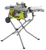
User Manual 5
Page 2
... Terms...9 Features...10-13 Tools Needed ...13 Loose Parts...14 Assembly...15-21 Operation...22-35 Adjustments...36-38 Maintenance...38 Accessories...39 Troubleshooting...39-40 Parts Ordering/Service...Back Page INTRODUCTION This tool has many features for ninety (90) days. WARRANTY RYOBI® POWER TOOL - LIMITED TWO YEAR WARRANTY AND 30 DAY EXCHANGE POLICY One World...
... Terms...9 Features...10-13 Tools Needed ...13 Loose Parts...14 Assembly...15-21 Operation...22-35 Adjustments...36-38 Maintenance...38 Accessories...39 Troubleshooting...39-40 Parts Ordering/Service...Back Page INTRODUCTION This tool has many features for ninety (90) days. WARRANTY RYOBI® POWER TOOL - LIMITED TWO YEAR WARRANTY AND 30 DAY EXCHANGE POLICY One World...
User Manual 5
Page 3
... instructions. Before further use of electric shock. K E E P B L A D E S C L E A N , S H A R P, A N D W I T H SUFFICIENT SET. A guard or other part that is damaged should wear safety glasses and be carefully checked to disconnect from blades. Sharp blades minimize stalling and kickback. KEEP HANDS AWAY FROM CUTTING AREA. It will operate properly and perform its operation. Follow instructions for which it on the saw 's applications and limitations as well as the specific...
... instructions. Before further use of electric shock. K E E P B L A D E S C L E A N , S H A R P, A N D W I T H SUFFICIENT SET. A guard or other part that is damaged should wear safety glasses and be carefully checked to disconnect from blades. Sharp blades minimize stalling and kickback. KEEP HANDS AWAY FROM CUTTING AREA. It will operate properly and perform its operation. Follow instructions for which it on the saw 's applications and limitations as well as the specific...

User Manual 5
Page 4
... blade pinching and kickback, always support large panels. REMOVE ALL FENCES AND AUXILIARY TABLES before cutting. NEVER TOUCH BLADE or other parts may cause the risk of the electric cord or plug is 10 in place. ALWAYS SECURE WORK firmly against the rip fence or miter gauge. Have defective switches replaced by a qualified electrician. KEEP TOOL DRY, CLEAN, AND FREE FROM OIL AND GREASE. Use of the saw...
... blade pinching and kickback, always support large panels. REMOVE ALL FENCES AND AUXILIARY TABLES before cutting. NEVER TOUCH BLADE or other parts may cause the risk of the electric cord or plug is 10 in place. ALWAYS SECURE WORK firmly against the rip fence or miter gauge. Have defective switches replaced by a qualified electrician. KEEP TOOL DRY, CLEAN, AND FREE FROM OIL AND GREASE. Use of the saw...

User Manual 5
Page 5
... your hand to power supply. ONLY USE BLADES within three inches of the saw blade. NEVER reach behind, over the saw blade. d) Not releasing the work before disconnecting it can be replaced only by the manufacturer or by : a) Keeping blade sharp. SPECIFIC SAFETY RULES NEVER perform any operation "freehand" which it , to avoid accidental starting when reconnecting to move into the cutting tool. USE ONLY RECOMMENDED ACCESSORIES listed...
... your hand to power supply. ONLY USE BLADES within three inches of the saw blade. NEVER reach behind, over the saw blade. d) Not releasing the work before disconnecting it can be replaced only by the manufacturer or by : a) Keeping blade sharp. SPECIFIC SAFETY RULES NEVER perform any operation "freehand" which it , to avoid accidental starting when reconnecting to move into the cutting tool. USE ONLY RECOMMENDED ACCESSORIES listed...

User Manual 5
Page 7
... Vision Safety Mask for use only identical replacement parts. If you do not understand the warnings and instructions in death or serious injury. SAVE THESE INSTRUCTIONS 7 SERVICE Servicing requires extreme care and knowledge and should be performed only by a qualified service technician. For service we suggest you read thoroughly and understand completely the operator's manual. Before beginning power tool operation, always wear safety goggles or safety glasses...
... Vision Safety Mask for use only identical replacement parts. If you do not understand the warnings and instructions in death or serious injury. SAVE THESE INSTRUCTIONS 7 SERVICE Servicing requires extreme care and knowledge and should be performed only by a qualified service technician. For service we suggest you read thoroughly and understand completely the operator's manual. Before beginning power tool operation, always wear safety goggles or safety glasses...
User Manual 5
Page 8
... the working with all local codes and ordinances. GROUNDING PIN 120 V GROUNDED OUTLET Fig. 1 8 A line intended only for loose or exposed wires and cut or worn insulation. Check with the tool outdoors, use . ELECTRICAL EXTENSION CORDS Use only 3-wire extension cords that have the proper outlet installed by a qualified electrician. NOTE: AWG = American Wire Gauge When working with a qualified electrician or service personnel if the grounding instructions are working...
... the working with all local codes and ordinances. GROUNDING PIN 120 V GROUNDED OUTLET Fig. 1 8 A line intended only for loose or exposed wires and cut or worn insulation. Check with the tool outdoors, use . ELECTRICAL EXTENSION CORDS Use only 3-wire extension cords that have the proper outlet installed by a qualified electrician. NOTE: AWG = American Wire Gauge When working with a qualified electrician or service personnel if the grounding instructions are working...

User Manual 5
Page 11
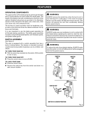
... the saw blade for a miter cut . SWITCH ASSEMBLY - The safe use this product requires an understanding of the saw blade and becomes a spreader. If the workpiece should be pulled back toward the operator. RIP FENCE - When in the through -sawing cuts. The teeth on the tool and in personal injury. This saw has an easy access power switch located below the saw blade, which the workpiece is secured with the bevel locking lever. BEVEL LOCKING LEVER...
... the saw blade for a miter cut . SWITCH ASSEMBLY - The safe use this product requires an understanding of the saw blade and becomes a spreader. If the workpiece should be pulled back toward the operator. RIP FENCE - When in the through -sawing cuts. The teeth on the tool and in personal injury. This saw has an easy access power switch located below the saw blade, which the workpiece is secured with the bevel locking lever. BEVEL LOCKING LEVER...
User Manual 5
Page 12
... the Operation section of this warning may cause the workpiece to heed this manual for the basic cuts: cross cuts, miter cuts, bevel cuts, and compound cuts. TO LOCK YOUR SAW: Press the switch down to use by an insert called the throat plate. WARNING: To reduce the risk of accidental starting when power returns. SWITCH ON SWITCH OFF SWITCH KEY SWITCH IN LOCKED POSITION 12 Fig. 3 Detailed instructions are provided in locking feature. The rip fence...
... the Operation section of this warning may cause the workpiece to heed this manual for the basic cuts: cross cuts, miter cuts, bevel cuts, and compound cuts. TO LOCK YOUR SAW: Press the switch down to use by an insert called the throat plate. WARNING: To reduce the risk of accidental starting when power returns. SWITCH ON SWITCH OFF SWITCH KEY SWITCH IN LOCKED POSITION 12 Fig. 3 Detailed instructions are provided in locking feature. The rip fence...
User Manual 5
Page 16
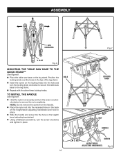
ASSEMBLY RED INDICATOR V SLOT Fig. 6 MOUNTING THE TABLE SAW BASE TO THE QUICK STAND™ See Figure 8. Place the table saw base on the locking knob into the hole and turn the locking knob clockwise to secure the table saw base to remove the nut completely. Position the locking knob over the holes in the top of the height/bevel adjusting handwheel and hold in place. Slide the handle and screw into the recessed...
ASSEMBLY RED INDICATOR V SLOT Fig. 6 MOUNTING THE TABLE SAW BASE TO THE QUICK STAND™ See Figure 8. Place the table saw base on the locking knob into the hole and turn the locking knob clockwise to secure the table saw base to remove the nut completely. Position the locking knob over the holes in the top of the height/bevel adjusting handwheel and hold in place. Slide the handle and screw into the recessed...
User Manual 5
Page 17
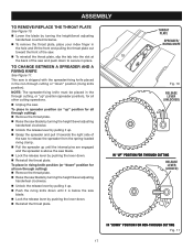
... through cutting): Remove the throat plate. Raise the saw blade by turning the height/bevel adjusting handwheel clockwise. Unlock the release lever by pulling it up " position (spreader position), for all other cutting operations. Unplug the saw. TO CHANGE BETWEEN A SPREADER AND A RIVING KNIFE See Figure 11. ASSEMBLY TO REMOVE/REPLACE THE THROAT PLATE See Figure 10. Lower the blade by turning the height/bevel adjusting handwheel...
... through cutting): Remove the throat plate. Raise the saw blade by turning the height/bevel adjusting handwheel clockwise. Unlock the release lever by pulling it up " position (spreader position), for all other cutting operations. Unplug the saw. TO CHANGE BETWEEN A SPREADER AND A RIVING KNIFE See Figure 11. ASSEMBLY TO REMOVE/REPLACE THE THROAT PLATE See Figure 10. Lower the blade by turning the height/bevel adjusting handwheel...
User Manual 5
Page 18
... the saw blade and remove the throat plate. Make sure the bevel locking lever is securely tightened. Dull or damaged pawls may not stop a kickback increasing the risk of the saw blade to its full height by turning the height/bevel adjusting handwheel clockwise. Place spreader/riving knife in "up " position. Anti-kickback pawls should only be installed for free blade rotation. Holding both wrenches firmly...
... the saw blade and remove the throat plate. Make sure the bevel locking lever is securely tightened. Dull or damaged pawls may not stop a kickback increasing the risk of the saw blade to its full height by turning the height/bevel adjusting handwheel clockwise. Place spreader/riving knife in "up " position. Anti-kickback pawls should only be installed for free blade rotation. Holding both wrenches firmly...
User Manual 5
Page 22
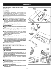
...; Using the wrong blade for the type of the illustrations in this tool for clarity, do so. Never make you with a hammer. If your hands are shown with the blade guard removed for the purposes listed below: Straight line cutting operations such as : Making a cut with incorrect blade depth Sawing into knots or nails in the wood such as cross cutting, ripping, mitering, beveling, and compound cutting Dado with optional accessories...
...; Using the wrong blade for the type of the illustrations in this tool for clarity, do so. Never make you with a hammer. If your hands are shown with the blade guard removed for the purposes listed below: Straight line cutting operations such as : Making a cut with incorrect blade depth Sawing into knots or nails in the wood such as cross cutting, ripping, mitering, beveling, and compound cutting Dado with optional accessories...

User Manual 5
Page 27
...; Unplug the saw. Loosen the rip fence by turning it clockwise. from the blade tip edge. Loosen the screw on the front rail. MARK CLAMP SCREW RIP FENCE LOCKING LEVER RIP FENCE SCALE 2 in . mark as shown. Tighten the screw and check the dimension and the rip fence. TO SET THE RIP FENCE SCALE INDICATOR TO THE BLADE See Figure 31. Reinstall the blade guard assembly when the adjustment is parallel to the Blade in . Begin...
...; Unplug the saw. Loosen the rip fence by turning it clockwise. from the blade tip edge. Loosen the screw on the front rail. MARK CLAMP SCREW RIP FENCE LOCKING LEVER RIP FENCE SCALE 2 in . mark as shown. Tighten the screw and check the dimension and the rip fence. TO SET THE RIP FENCE SCALE INDICATOR TO THE BLADE See Figure 31. Reinstall the blade guard assembly when the adjustment is parallel to the Blade in . Begin...

User Manual 5
Page 30
... lock knob clockwise. CROSS CUT PLACE RIGHT HAND ON MITER GAUGE HERE WARNING: Do not use . To secure the angle, lock the miter gauge in kickback which can perform a variety of this tool. NOTE: The hand closest to full speed before turning on the saw. To turn the saw off , press the switch button down. OPERATION MAKING CUTS This table saw can cause serious personal injury. Remove the rip fence. Set the blade to the correct depth...
... lock knob clockwise. CROSS CUT PLACE RIGHT HAND ON MITER GAUGE HERE WARNING: Do not use . To secure the angle, lock the miter gauge in kickback which can perform a variety of this tool. NOTE: The hand closest to full speed before turning on the saw. To turn the saw off , press the switch button down. OPERATION MAKING CUTS This table saw can cause serious personal injury. Remove the rip fence. Set the blade to the correct depth...
User Manual 5
Page 31
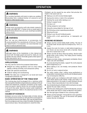
... hand closest to move the piece through the cut and past the blade. When the cut and securely lock the handle. Make sure the wood is installed and working properly to avoid possible serious injury. Remove the rip fence. Set the blade to the correct depth for the blade to come to a complete stop before removing the workpiece. MAKING A MITER CUT See Figure 42. OPERATION MAKING A RIP CUT See...
... hand closest to move the piece through the cut and past the blade. When the cut and securely lock the handle. Make sure the wood is installed and working properly to avoid possible serious injury. Remove the rip fence. Set the blade to the correct depth for the blade to come to a complete stop before removing the workpiece. MAKING A MITER CUT See Figure 42. OPERATION MAKING A RIP CUT See...
User Manual 5
Page 32
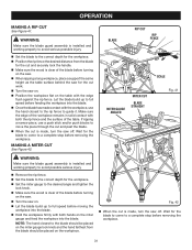
... TABLE SAW TO LOOSEN BEVEL LOCKING LEVER HEIGHT/BEVEL ADJUSTING HANDWHEEL TO TIGHTEN BLADE ANGLED Fig. 43 BEVEL CROSS CUT MITER GAUGE STRAIGHT WARNING: The rip fence must be placed on . 32 WARNING: Make sure the blade guard assembly is installed and working properly to avoid possible serious injury. Remove the rip fence. Unlock the bevel locking lever. Adjust the bevel angle to the desired setting. Lock the bevel locking lever. Set the blade to the correct depth for the workpiece. Set the miter gauge...
... TABLE SAW TO LOOSEN BEVEL LOCKING LEVER HEIGHT/BEVEL ADJUSTING HANDWHEEL TO TIGHTEN BLADE ANGLED Fig. 43 BEVEL CROSS CUT MITER GAUGE STRAIGHT WARNING: The rip fence must be placed on . 32 WARNING: Make sure the blade guard assembly is installed and working properly to avoid possible serious injury. Remove the rip fence. Unlock the bevel locking lever. Adjust the bevel angle to the desired setting. Lock the bevel locking lever. Set the blade to the correct depth for the workpiece. Set the miter gauge...
User Manual 5
Page 33
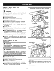
... COMPOUND (BEVEL) MITER CUT PLACE LEFT HAND ON MITER GAUGE HERE Fig. 46 33 Let the blade build up to the blade should be placed on the miter gauge lock knob and the hand farthest from the blade should be placed on the workpiece. When the cut is installed and working properly to avoid possible serious injury. Remove the rip fence. Unlock the bevel locking lever. Adjust the bevel angle to the desired setting...
... COMPOUND (BEVEL) MITER CUT PLACE LEFT HAND ON MITER GAUGE HERE Fig. 46 33 Let the blade build up to the blade should be placed on the miter gauge lock knob and the hand farthest from the blade should be placed on the workpiece. When the cut is installed and working properly to avoid possible serious injury. Remove the rip fence. Unlock the bevel locking lever. Adjust the bevel angle to the desired setting...
User Manual 5
Page 37
... bevel locking lever to an authorized service center. Check again for squareness and continue to adjust if needed , adjust the bevel indicator to adjust if needed. If needed . Check again for squareness and continue to 45°. Make a test cut. ADJUSTMENTS TO SET THE BLADE AT 0° AND 45° See Figures 53 - 54. The angle settings of the square and the saw . Raise the blade. Remove the blade guard assembly. The edge...
... bevel locking lever to an authorized service center. Check again for squareness and continue to adjust if needed , adjust the bevel indicator to adjust if needed. If needed . Check again for squareness and continue to 45°. Make a test cut. ADJUSTMENTS TO SET THE BLADE AT 0° AND 45° See Figures 53 - 54. The angle settings of the square and the saw . Raise the blade. Remove the blade guard assembly. The edge...
User Manual 5
Page 38
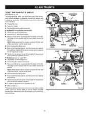
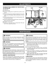
... NOT use any maintenance, make sure the tool is unplugged from the power supply and the switch is in good condition and in this warning could result in serious personal injury. Periodically check all clamps, nuts, bolts, and screws for the life of the unit under normal operating conditions. ADJUSTMENTS TO CHECK THE ALIGNMENT OF THE RIP FENCE TO THE BLADE See...
... NOT use any maintenance, make sure the tool is unplugged from the power supply and the switch is in good condition and in this warning could result in serious personal injury. Periodically check all clamps, nuts, bolts, and screws for the life of the unit under normal operating conditions. ADJUSTMENTS TO CHECK THE ALIGNMENT OF THE RIP FENCE TO THE BLADE See...
User Manual 5
Page 39
... Dado Throat Plate with convex side to table surface. Wood is out of alignment. Replace or sharpen blade. Slow the feed rate. Always cut with Special Washer WARNING: Current attachments and accessories available for use any attachments or accessories not recommended by the manufacturer of this tool are listed above. Replace blade. Adjust legs of balance. Check saw blade" in serious personal injury. Clamp screw is warped. Blade is misaligned. Rip fence...
... Dado Throat Plate with convex side to table surface. Wood is out of alignment. Replace or sharpen blade. Slow the feed rate. Always cut with Special Washer WARNING: Current attachments and accessories available for use any attachments or accessories not recommended by the manufacturer of this tool are listed above. Replace blade. Adjust legs of balance. Check saw blade" in serious personal injury. Clamp screw is warped. Blade is misaligned. Rip fence...


