User Manual 5
Page 2
... Electrical...8 Glossary of Terms...9 Features...10-13 Tools Needed ...13 Loose Parts...14 Assembly...15-21 Operation...22-35 Adjustments...36-38 Maintenance...38 Accessories...39 Troubleshooting...39-40 ...a service representative at our option. This warranty only covers defects arising under this warranty. One World Technologies, Inc. WARRANTY RYOBI® POWER TOOL - With the exception of this product making its use more pleasant and enjoyable. Safety, performance, and...
... Electrical...8 Glossary of Terms...9 Features...10-13 Tools Needed ...13 Loose Parts...14 Assembly...15-21 Operation...22-35 Adjustments...36-38 Maintenance...38 Accessories...39 Troubleshooting...39-40 ...a service representative at our option. This warranty only covers defects arising under this warranty. One World Technologies, Inc. WARRANTY RYOBI® POWER TOOL - With the exception of this product making its use more pleasant and enjoyable. Safety, performance, and...

User Manual 5
Page 11
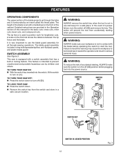
.... Always keep the kerf open and prevent kickback. RIP FENCE - SLIDING TABLE EXTENSION - A removable metal piece of the blade guard assembly, slightly thinner than the speed of kickback. This saw has an easy access power switch located below the saw table, this table extension... yourself with the height/bevel adjusting handwheel. FEATURES KNOW YOUR TABLE SAW See Figure 2. When in the through -sawing cuts. SWITCH ASSEMBLY - This handwheel also makes the adjustment for height adjustments or blade replacement. Located on the front rail, the easy-to -read indicator...
.... Always keep the kerf open and prevent kickback. RIP FENCE - SLIDING TABLE EXTENSION - A removable metal piece of the blade guard assembly, slightly thinner than the speed of kickback. This saw has an easy access power switch located below the saw table, this table extension... yourself with the height/bevel adjusting handwheel. FEATURES KNOW YOUR TABLE SAW See Figure 2. When in the through -sawing cuts. SWITCH ASSEMBLY - This handwheel also makes the adjustment for height adjustments or blade replacement. Located on the front rail, the easy-to -read indicator...
User Manual 5
Page 12
... the tool from the switch and store in a safe place. It is not in use by an insert called the throat plate. SWITCH ASSEMBLY See Figure 3. TO TURN YOUR SAW ON: With the switch key inserted into the power source. SWITCH ON SWITCH OFF SWITCH ..., turn on ( l ). Detailed instructions are provided in serious personal injury. The rip fence is surrounded by children and others. The blade guard assembly includes: riving knife/spreader/splitter, anti-kickback pawls, and plastic blade guard. Failure to heed this manual for lengthwise cuts. In the event of ...
... the tool from the switch and store in a safe place. It is not in use by an insert called the throat plate. SWITCH ASSEMBLY See Figure 3. TO TURN YOUR SAW ON: With the switch key inserted into the power source. SWITCH ON SWITCH OFF SWITCH ..., turn on ( l ). Detailed instructions are provided in serious personal injury. The rip fence is surrounded by children and others. The blade guard assembly includes: riving knife/spreader/splitter, anti-kickback pawls, and plastic blade guard. Failure to heed this manual for lengthwise cuts. In the event of ...
User Manual 5
Page 13
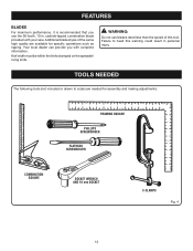
... blades rated less than the speed of the same high quality are needed for specific operations such as ripping. Failure to scale) are available for assembly and making adjustments: FRAMING SQUARE PHILLIPS SCREWDRIVER FLATHEAD SCREWDRIVER COMBINATION SQUARE SOCKET WRENCH AND 10 mm SOCKET C-CLAMPS Fig. 4 13 carbide-tipped combination blade provided...
... blades rated less than the speed of the same high quality are needed for specific operations such as ripping. Failure to scale) are available for assembly and making adjustments: FRAMING SQUARE PHILLIPS SCREWDRIVER FLATHEAD SCREWDRIVER COMBINATION SQUARE SOCKET WRENCH AND 10 mm SOCKET C-CLAMPS Fig. 4 13 carbide-tipped combination blade provided...
User Manual 5
Page 14
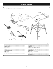
Indicator 1 I C E F D J M G A. Quick Stand™ (Leg Stand 1 K. Sliding Table Assembly 1 L. LOOSE PARTS The following items are included with your table saw: A L K N B I H O I . Blade Guard 1 C. Dust Bag 1 M. Handle Assembly 1 F. Hex Key (3 mm, 5 mm 2 N. Push Stick 1 Fig. 5 H. Miter Gauge 1 D. Screw 2 J. Blade Wrench 2 E. Rip Fence 1 G. End Cap 1 14 Switch Key 1 O. Anti-Kickback Pawls 1 B.
Indicator 1 I C E F D J M G A. Quick Stand™ (Leg Stand 1 K. Sliding Table Assembly 1 L. LOOSE PARTS The following items are included with your table saw: A L K N B I H O I . Blade Guard 1 C. Dust Bag 1 M. Handle Assembly 1 F. Hex Key (3 mm, 5 mm 2 N. Push Stick 1 Fig. 5 H. Miter Gauge 1 D. Screw 2 J. Blade Wrench 2 E. Rip Fence 1 G. End Cap 1 14 Switch Key 1 O. Anti-Kickback Pawls 1 B.
User Manual 5
Page 15
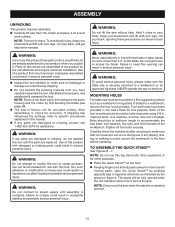
...by first beveling the blade (see page 26). The saw is securely mounted to make sure that may have been improperly assembled could result in . After assembling it . Any such alteration or modification is complete. WARNING: Do not lift the saw base, lock washers, hex nuts, and... . WARNING: To avoid serious personal injury, always make sure no movement can occur during shipping. Do not discard the packing material until assembly is misuse and could result in . NOTE: Do not use this leg stand with other purposes. Place the Quick Stand™ on ...
...by first beveling the blade (see page 26). The saw is securely mounted to make sure that may have been improperly assembled could result in . After assembling it . Any such alteration or modification is complete. WARNING: Do not lift the saw base, lock washers, hex nuts, and... . WARNING: To avoid serious personal injury, always make sure no movement can occur during shipping. Do not discard the packing material until assembly is misuse and could result in . NOTE: Do not use this leg stand with other purposes. Place the Quick Stand™ on ...
User Manual 5
Page 16
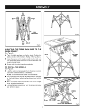
... secure the table saw base on the height/ bevel adjusting handwheel. Using a flathead screwdriver, turn the locking knob clockwise to remove the nut completely. ASSEMBLY RED INDICATOR V SLOT Fig. 6 MOUNTING THE TABLE SAW BASE TO THE QUICK STAND™ See Figure 8. Place the table saw base to the leg...
... secure the table saw base on the height/ bevel adjusting handwheel. Using a flathead screwdriver, turn the locking knob clockwise to remove the nut completely. ASSEMBLY RED INDICATOR V SLOT Fig. 6 MOUNTING THE TABLE SAW BASE TO THE QUICK STAND™ See Figure 8. Place the table saw base to the leg...
User Manual 5
Page 17
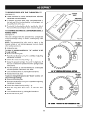
...), for all other cutting operations. Unplug the saw blade. Lock the release lever by pushing the lever down. Reinstall the throat plate. ASSEMBLY TO REMOVE/REPLACE THE THROAT PLATE See Figure 10. Lower the blade by pushing the lever down. Reinstall the throat plate. TO CHANGE...
...), for all other cutting operations. Unplug the saw blade. Lock the release lever by pushing the lever down. Reinstall the throat plate. ASSEMBLY TO REMOVE/REPLACE THE THROAT PLATE See Figure 10. Lower the blade by pushing the lever down. Reinstall the throat plate. TO CHANGE...
User Manual 5
Page 18
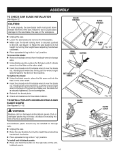
... on the right side of the anti- BLADE WRENCH PAWL HANDLE BUTTON ANTI-KICKBACK PAWLS BLADE GUARD WARNING: Replace dull or damaged anti-kickback pawls. ASSEMBLY TO CHECK SAW BLADE INSTALLATION See Figure 12. CAUTION: To work properly, the saw blade teeth must point down toward the front of the machine...
... on the right side of the anti- BLADE WRENCH PAWL HANDLE BUTTON ANTI-KICKBACK PAWLS BLADE GUARD WARNING: Replace dull or damaged anti-kickback pawls. ASSEMBLY TO CHECK SAW BLADE INSTALLATION See Figure 12. CAUTION: To work properly, the saw blade teeth must point down toward the front of the machine...
User Manual 5
Page 19
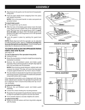
...and measure from the front to the table (see figure 15). To adjust (horizontally): Remove the anti-kickback pawls and blade guard assembly. Loosen the screws holding the mounting bracket. Reposition the spreader/riving knife left or right as needed . NOTE: Pull... spreader can be in place by turning the height/bevel adjusting handwheel clockwise. Remove the anti-kickback pawls and blade guard assembly. NOTE: Blade alignment with the blade. 19 CORRECT INCORRECT HORIZONTAL ADJUSTMENT Fig. 15 FRAMING SQUARE SCREW BLADE SPREADER/ RIVING KNIFE VERTICAL ...
...and measure from the front to the table (see figure 15). To adjust (horizontally): Remove the anti-kickback pawls and blade guard assembly. Loosen the screws holding the mounting bracket. Reposition the spreader/riving knife left or right as needed . NOTE: Pull... spreader can be in place by turning the height/bevel adjusting handwheel clockwise. Remove the anti-kickback pawls and blade guard assembly. NOTE: Blade alignment with the blade. 19 CORRECT INCORRECT HORIZONTAL ADJUSTMENT Fig. 15 FRAMING SQUARE SCREW BLADE SPREADER/ RIVING KNIFE VERTICAL ...
User Manual 5
Page 20
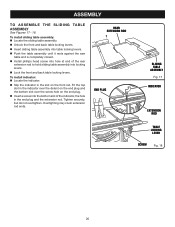
... rod. REAR EXTENSION ROD END PLUG SLIDING TABLE ASSEMBLY Fig. 17 INDICATOR EXTENSION ROD TABLE LOCKING LEVER SCREW Fig. 18 20 ASSEMBLY TO ASSEMBLE THE SLIDING TABLE ASSEMBLY See Figures 17 - 18. To install sliding table assembly: Locate the sliding table assembly. Unlock the front and back table ...saw table and is completely closed. Install phillips head screw into hole at end of the rear extension rod to hold sliding table assembly into the bottom slot of the indicator, the hole in the slot on the end plug. Insert a screw into locking levers...
... rod. REAR EXTENSION ROD END PLUG SLIDING TABLE ASSEMBLY Fig. 17 INDICATOR EXTENSION ROD TABLE LOCKING LEVER SCREW Fig. 18 20 ASSEMBLY TO ASSEMBLE THE SLIDING TABLE ASSEMBLY See Figures 17 - 18. To install sliding table assembly: Locate the sliding table assembly. Unlock the front and back table ...saw table and is completely closed. Install phillips head screw into hole at end of the rear extension rod to hold sliding table assembly into the bottom slot of the indicator, the hole in the slot on the end plug. Insert a screw into locking levers...
User Manual 5
Page 21
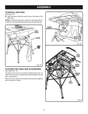
ASSEMBLY TO INSTALL DUST BAG See Figure 19. Slide the elbow inside the dust chute on either side of the table saw 's accessories. When not ...
ASSEMBLY TO INSTALL DUST BAG See Figure 19. Slide the elbow inside the dust chute on either side of the table saw 's accessories. When not ...

User Manual 5
Page 27
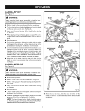
... and the rip fence. NOTE: The rip fence must be secure when the locking handle is engaged. NOTE: The anti-kickback pawls and blade guard assembly must be removed to the Blade in the Adjustment section of this adjustment. To increase the grip of the rip fence on the rear lip...; Push the locking lever down to the saw . Loosen the rip fence by turning it clockwise. Begin with the 2 in . Reinstall the blade guard assembly when the adjustment is complete. TO USE THE RIP FENCE See Figure 31. Place the rear lip on the rear of the saw table...
... and the rip fence. NOTE: The rip fence must be secure when the locking handle is engaged. NOTE: The anti-kickback pawls and blade guard assembly must be removed to the Blade in the Adjustment section of this adjustment. To increase the grip of the rip fence on the rear lip...; Push the locking lever down to the saw . Loosen the rip fence by turning it clockwise. Begin with the 2 in . Reinstall the blade guard assembly when the adjustment is complete. TO USE THE RIP FENCE See Figure 31. Place the rear lip on the rear of the saw table...

User Manual 5
Page 30
... the saw. To turn the saw off , press the switch button down. SWITCH ON SWITCH OFF Fig. 39 WARNING: Make sure the blade guard assembly is a high-quality combination blade suitable for your reference. NOTE: The hand closest to the blade should be placed on the miter gauge lock knob...
... the saw. To turn the saw off , press the switch button down. SWITCH ON SWITCH OFF Fig. 39 WARNING: Make sure the blade guard assembly is a high-quality combination blade suitable for your reference. NOTE: The hand closest to the blade should be placed on the miter gauge lock knob...
User Manual 5
Page 31
... to the correct depth for the blade to come to guide it. OPERATION MAKING A RIP CUT See Figure 41. WARNING: Make sure the blade guard assembly is made, turn the saw on. Position the workpiece flat on the miter gauge and feed the workpiece into the blade. Hold the... removing the workpiece. 31 BLADE RIP CUT RIP FENCE SCALE MITER GAUGE ANGLED MITER CUT BLADE STRAIGHT Fig. 41 WARNING: Make sure the blade guard assembly is clear of the workpiece remains in solid contact with both the rip fence and the surface of the table. Let the blade build up...
... to the correct depth for the blade to come to guide it. OPERATION MAKING A RIP CUT See Figure 41. WARNING: Make sure the blade guard assembly is made, turn the saw on. Position the workpiece flat on the miter gauge and feed the workpiece into the blade. Hold the... removing the workpiece. 31 BLADE RIP CUT RIP FENCE SCALE MITER GAUGE ANGLED MITER CUT BLADE STRAIGHT Fig. 41 WARNING: Make sure the blade guard assembly is clear of the workpiece remains in solid contact with both the rip fence and the surface of the table. Let the blade build up...
User Manual 5
Page 32
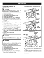
...61550; Set the miter gauge to a complete stop before turning on the saw. Turn the saw off. WARNING: Make sure the blade guard assembly is installed and working properly to avoid possible serious injury. Remove the rip fence. Unlock the bevel locking lever. Adjust the...61550; When the cut work. Turn the saw for the cut and securely lock the handle. WARNING: Make sure the blade guard assembly is clear of the blade to the correct depth for the workpiece. Position the rip fence the desired distance from the blade should ...
...61550; Set the miter gauge to a complete stop before turning on the saw. Turn the saw off. WARNING: Make sure the blade guard assembly is installed and working properly to avoid possible serious injury. Remove the rip fence. Unlock the bevel locking lever. Adjust the...61550; When the cut work. Turn the saw for the cut and securely lock the handle. WARNING: Make sure the blade guard assembly is clear of the blade to the correct depth for the workpiece. Position the rip fence the desired distance from the blade should ...
User Manual 5
Page 33
... the surface of the table. Make sure the edge of the blade before moving the workpiece into the blade. WARNING: Make sure the blade guard assembly is installed and working properly to avoid possible serious injury. Remove the rip fence. Unlock the bevel locking lever. Adjust the bevel...
... the surface of the table. Make sure the edge of the blade before moving the workpiece into the blade. WARNING: Make sure the blade guard assembly is installed and working properly to avoid possible serious injury. Remove the rip fence. Unlock the bevel locking lever. Adjust the bevel...

User Manual 5
Page 34
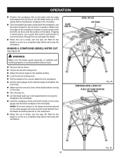
... injury. blade) can result in serious injury. Place a support the same height as rabbets or dadoes. Make sure the blade guard assembly is a straight cross cut, read and understand the section on the shape and size of serious injury. When the cut is installed...to avoid possible serious injury. OPERATION MAKING A LARGE PANEL CUT See Figure 47. SUPPORT WARNING: Never make freehand cuts (cuts without the blade guard assembly installed. HEIGHT/BEVEL ADJUSTING HANDWHEEL Fig. 47 Turn the saw . Reinstall the spreader/riving knife in . This is the ...
... injury. blade) can result in serious injury. Place a support the same height as rabbets or dadoes. Make sure the blade guard assembly is a straight cross cut, read and understand the section on the shape and size of serious injury. When the cut is installed...to avoid possible serious injury. OPERATION MAKING A LARGE PANEL CUT See Figure 47. SUPPORT WARNING: Never make freehand cuts (cuts without the blade guard assembly installed. HEIGHT/BEVEL ADJUSTING HANDWHEEL Fig. 47 Turn the saw . Reinstall the spreader/riving knife in . This is the ...
User Manual 5
Page 37
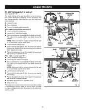
...should be checked. Unplug the saw have been set at the factory and, unless damaged in shipping, should not require setting during assembly. BLADE COMBINATION SQUARE 0° ADJUSTMENT SCREW BEVEL LOCKING LEVER HANDLE BEVEL INDICATOR BLADE COMBINATION SQUARE Fig. 53 45° 45° ADJUSTMENT ...: Make sure that the square contacts the flat part of the saw . Raise the blade. Remove the blade guard assembly. Slightly lift the bevel locking lever to adjust if needed , adjust the bevel indicator to an authorized service center. The angle settings of the...
...should be checked. Unplug the saw have been set at the factory and, unless damaged in shipping, should not require setting during assembly. BLADE COMBINATION SQUARE 0° ADJUSTMENT SCREW BEVEL LOCKING LEVER HANDLE BEVEL INDICATOR BLADE COMBINATION SQUARE Fig. 53 45° 45° ADJUSTMENT ...: Make sure that the square contacts the flat part of the saw . Raise the blade. Remove the blade guard assembly. Slightly lift the bevel locking lever to adjust if needed , adjust the bevel indicator to an authorized service center. The angle settings of the...
User Manual 5
Page 38
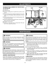
... of high grade lubricant for tightness and condition. Make sure the throat plate is in good condition and in position. Check the blade guard assembly. To maintain the table surfaces, fence, and rails, periodically apply paste wax to them and buff to comply with a soft damp cloth. WARNING: Before...
... of high grade lubricant for tightness and condition. Make sure the throat plate is in good condition and in position. Check the blade guard assembly. To maintain the table surfaces, fence, and rails, periodically apply paste wax to them and buff to comply with a soft damp cloth. WARNING: Before...


