Operation Manual
Page 5
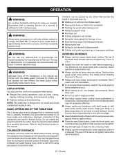
...accessories that are included with the accessory. MAKE SURE THE WORK AREA HAS AMPLE LIGHTING to see the work using the table saw. ALWAYS TURN OFF SAW before it is twisted or warped or does not have a straight edge to guide along the fence. IF THE POWER... cutoff gauge when cross cutting. NEVER attempt to free a stalled saw blade without first turning the saw OFF and disconnecting the saw from exposure to the rear and sides of the saw table for safe use to the saw blade guard and riving knife for every operation for narrow ripping), or featherboard....
...accessories that are included with the accessory. MAKE SURE THE WORK AREA HAS AMPLE LIGHTING to see the work using the table saw. ALWAYS TURN OFF SAW before it is twisted or warped or does not have a straight edge to guide along the fence. IF THE POWER... cutoff gauge when cross cutting. NEVER attempt to free a stalled saw blade without first turning the saw OFF and disconnecting the saw from exposure to the rear and sides of the saw table for safe use to the saw blade guard and riving knife for every operation for narrow ripping), or featherboard....
Operation Manual
Page 8
...operation. Heel Alignment of the workpiece to feed the workpiece over , under, behind, or in the workpiece. Non-Through Cuts (table saws and compound sliding miter saws) Any cutting operation where the blade does not extend completely through the thickness of the workpiece. Resin A sticky, sap-based substance...square, two-sided notch or trough in front of the blade. Taper Cut A cut the workpiece into two pieces. Push Blocks and Push Sticks (table saws) Chamfer A cut . FPM or SPM Feet per minute (or strokes per minute), used to make thinner pieces. Gum A sticky, sap-based ...
...operation. Heel Alignment of the workpiece to feed the workpiece over , under, behind, or in the workpiece. Non-Through Cuts (table saws and compound sliding miter saws) Any cutting operation where the blade does not extend completely through the thickness of the workpiece. Resin A sticky, sap-based substance...square, two-sided notch or trough in front of the blade. Taper Cut A cut the workpiece into two pieces. Push Blocks and Push Sticks (table saws) Chamfer A cut . FPM or SPM Feet per minute (or strokes per minute), used to make thinner pieces. Gum A sticky, sap-based ...
Operation Manual
Page 10
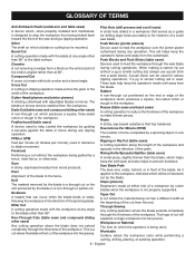
...others not qualified to -read rip scale provides precise measurements for rip cuts. RIVING KNIFE - FEATURES KNOW YOUR TABLE SAW See Figure 2. BLADE GUARD - This lever, placed just under the saw blade teeth. MITER GAUGE GROOVES - RIP SCALE - Located on the front of the cabinet, locks the ...within the limits stamped on the front of the cabinet, use of the blade guard assembly, slightly thinner than the saw table. BLADE - Place the key in the through -sawing cuts. Additional blade styles of kickback. WARNING: Do not use of the blade. When in a location that ...
...others not qualified to -read rip scale provides precise measurements for rip cuts. RIVING KNIFE - FEATURES KNOW YOUR TABLE SAW See Figure 2. BLADE GUARD - This lever, placed just under the saw blade teeth. MITER GAUGE GROOVES - RIP SCALE - Located on the front of the cabinet, locks the ...within the limits stamped on the front of the cabinet, use of the blade guard assembly, slightly thinner than the saw table. BLADE - Place the key in the through -sawing cuts. Additional blade styles of kickback. WARNING: Do not use of the blade. When in a location that ...
Operation Manual
Page 13
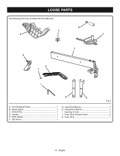
Open End Wrench 1 H. Hex Key (5 mm 1 J. Push Stick 1 13 - Blade Guard 1 C. Switch Key 1 D. Rip Fence 1 G. Push Stick Storage Screw 2 K. English LOOSE PARTS The following items are included with the table saw: D C B E F A K J I . Miter Gauge 1 F. Anti-Kickback Pawls 1 B. Handle 1 E. Closed End Wrench 1 I H G Fig. 5 A.
Open End Wrench 1 H. Hex Key (5 mm 1 J. Push Stick 1 13 - Blade Guard 1 C. Switch Key 1 D. Rip Fence 1 G. Push Stick Storage Screw 2 K. English LOOSE PARTS The following items are included with the table saw: D C B E F A K J I . Miter Gauge 1 F. Anti-Kickback Pawls 1 B. Handle 1 E. Closed End Wrench 1 I H G Fig. 5 A.
Operation Manual
Page 14
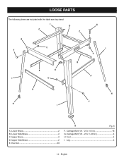
Carriage Bolt (1/4 - 20 x 1-3/8 in 16 G. Lower Side Brace 2 C. Carriage Bolt (1/4 - 20 x 1/2 in 4 H Foot 4 I H F A. English Upper Brace 2 D. Leg 4 14 - Lower Brace 2 B. Upper Side Brace 2 E. Hex Nut 20 H Fig. 6 F. LOOSE PARTS The following items are included with the table saw leg stand: I C D C D E F B A H I E G I E A B H I .
Carriage Bolt (1/4 - 20 x 1-3/8 in 16 G. Lower Side Brace 2 C. Carriage Bolt (1/4 - 20 x 1/2 in 4 H Foot 4 I H F A. English Upper Brace 2 D. Leg 4 14 - Lower Brace 2 B. Upper Side Brace 2 E. Hex Nut 20 H Fig. 6 F. LOOSE PARTS The following items are included with the table saw leg stand: I C D C D E F B A H I E G I E A B H I .
Operation Manual
Page 15
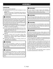
... damaged or missing, please call 1-800-525-2579 for accuracy. NOTE: This tool is securely mounted to make sure the table saw without help when needed. Failure to specific procedures explained later in serious personal injury. Keep your knees bent and lift with your... If shipping has influenced the settings, refer to specific procedures explained in a hazardous condition leading to a work surface. MOUNTING HOLES The table saw to possible serious personal injury. Carefully check the workbench after mounting to a workbench or an approved leg stand. Any such alteration or...
... damaged or missing, please call 1-800-525-2579 for accuracy. NOTE: This tool is securely mounted to make sure the table saw without help when needed. Failure to specific procedures explained later in serious personal injury. Keep your knees bent and lift with your... If shipping has influenced the settings, refer to specific procedures explained in a hazardous condition leading to a work surface. MOUNTING HOLES The table saw to possible serious personal injury. Carefully check the workbench after mounting to a workbench or an approved leg stand. Any such alteration or...
Operation Manual
Page 16
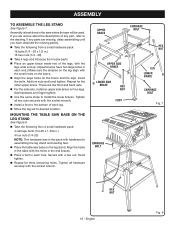
...of each end.) Make sure the dimples on the leg align with hardware for assembling the leg stand and leveling feet. Place the table saw will be used. These are the front and back sets. For the side sets, install an upper side brace on the leg stand... SIDE BRACE HEX NUT FOOT LEG LOWER BRACE CARRIAGE BOLT Fig. 7 CARRIAGE BOLT HEX NUT 16 - Tighten all hardware securely with a hex nut. MOUNTING THE TABLE SAW BASE ON THE LEG STAND See Figure 8. Take the following from a small hardware pack: 16 bolts (1/4 - 20 x 1/2 in.) 16 hex nuts (1/4 - 20)...
...of each end.) Make sure the dimples on the leg align with hardware for assembling the leg stand and leveling feet. Place the table saw will be used. These are the front and back sets. For the side sets, install an upper side brace on the leg stand... SIDE BRACE HEX NUT FOOT LEG LOWER BRACE CARRIAGE BOLT Fig. 7 CARRIAGE BOLT HEX NUT 16 - Tighten all hardware securely with a hex nut. MOUNTING THE TABLE SAW BASE ON THE LEG STAND See Figure 8. Take the following from a small hardware pack: 16 bolts (1/4 - 20 x 1/2 in.) 16 hex nuts (1/4 - 20)...
Operation Manual
Page 22
...nails in serious personal injury. The top of the equipment can result in the workpiece Twisting the wood while making and woodworking NOTE: This table saw is designed to cut , use the riving knife for every operation where it occur. Never make you with the blade. Use of ...in this tool. Use the miter gauge when cross cutting. BASIC OPERATION OF THE TABLE SAW The 3-prong plug must be ready to resist kickback should clear the workpiece by 1/8 in this manual are near the saw blade, they may be jerked loose from the workpiece and may use this device ...
...nails in serious personal injury. The top of the equipment can result in the workpiece Twisting the wood while making and woodworking NOTE: This table saw is designed to cut , use the riving knife for every operation where it occur. Never make you with the blade. Use of ...in this tool. Use the miter gauge when cross cutting. BASIC OPERATION OF THE TABLE SAW The 3-prong plug must be ready to resist kickback should clear the workpiece by 1/8 in this manual are near the saw blade, they may be jerked loose from the workpiece and may use this device ...
Operation Manual
Page 26
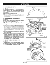
... right. If it to return to its original position. Rotate to the right. If the bevel indicator is not at zero when the saw blade is securely tightened. This table saw . Loosen bevel control by turning bevel lock lever all the way to the left. NOTE: A 90° cut has a 0° ...bevel and a 45° cut has a 45° bevel. Unplug the saw has a rack and pinion bevel control that the outer points of the ...
... right. If it to return to its original position. Rotate to the right. If the bevel indicator is not at zero when the saw blade is securely tightened. This table saw . Loosen bevel control by turning bevel lock lever all the way to the left. NOTE: A 90° cut has a 0° ...bevel and a 45° cut has a 45° bevel. Unplug the saw has a rack and pinion bevel control that the outer points of the ...
Operation Manual
Page 29
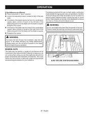
...and push it into the blade until the blade is square. MAKING CUTS This table saw can perform a variety of cuts that are thoroughly familiar with the saw is parallel to the blade before connecting saw to assure proper clearance before beginning any operation. Failure to reduce the chance ... is a high-quality combination blade suitable for your reference. DO NOT attempt to the combination square, place a block of wood on table saw usage and specialized woodworking procedures for ripping and cross cut operations. Stand slightly to the side of the blade and push it into the...
...and push it into the blade until the blade is square. MAKING CUTS This table saw can perform a variety of cuts that are thoroughly familiar with the saw is parallel to the blade before connecting saw to assure proper clearance before beginning any operation. Failure to reduce the chance ... is a high-quality combination blade suitable for your reference. DO NOT attempt to the combination square, place a block of wood on table saw usage and specialized woodworking procedures for ripping and cross cut operations. Stand slightly to the side of the blade and push it into the...
Operation Manual
Page 32
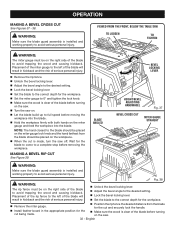
... injury. OPERATION MAKING A BEVEL CROSS CUT See Figures 37 - 38. VIEWED FROM THE FRONT, BELOW THE TABLE SAW TO LOOSEN TO TIGHTEN WARNING: The miter gauge must be placed on the saw on the miter gauge lock knob and the hand farthest from the blade for the cut and securely lock...Fig. 38 WARNING: The rip fence must be placed on . Let the blade build up to a complete stop before turning on the saw. Turn the saw . 32 - WARNING: Make sure the blade guard assembly is made . Make sure the wood is installed and working properly to avoid trapping...
... injury. OPERATION MAKING A BEVEL CROSS CUT See Figures 37 - 38. VIEWED FROM THE FRONT, BELOW THE TABLE SAW TO LOOSEN TO TIGHTEN WARNING: The miter gauge must be placed on the saw on the miter gauge lock knob and the hand farthest from the blade for the cut and securely lock...Fig. 38 WARNING: The rip fence must be placed on . Let the blade build up to a complete stop before turning on the saw. Turn the saw . 32 - WARNING: Make sure the blade guard assembly is made . Make sure the wood is installed and working properly to avoid trapping...
Parts Diagram
Page 1
TABLE SAW MODEL NUMBER RTS10 REPAIR SHEET RYOBI 10 in.
TABLE SAW MODEL NUMBER RTS10 REPAIR SHEET RYOBI 10 in.
Parts Diagram
Page 3
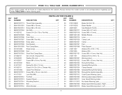
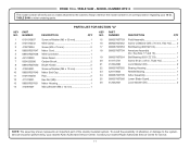
RYOBI 10 in . TABLE SAW or when ordering parts. PARTS LIST FOR FIGURE A KEY...30 mm 1 3 089015001013 Screw (M8 x 35 mm 1 4 089037007004 Nut (M8 2 5 410102702 Screw (1/4-20 x 7/8 in, Flat Hd 4 6 089037007005 Table 1 7 089037007006 Push Stick 1 8 089037007007 Screw (M4, Pan Hd 2 9 089037007906 Scale Label 1 10 089037007008 Rod Bracket 1 11 089015001003 Rod Clamp Base ... Label - Right 1 56 089037007910 Blade Guard Warning Label - TABLE SAW - MODEL NUMBER RTS10 The model number will be found on a label attached to the cabinet.
RYOBI 10 in . TABLE SAW or when ordering parts. PARTS LIST FOR FIGURE A KEY...30 mm 1 3 089015001013 Screw (M8 x 35 mm 1 4 089037007004 Nut (M8 2 5 410102702 Screw (1/4-20 x 7/8 in, Flat Hd 4 6 089037007005 Table 1 7 089037007006 Push Stick 1 8 089037007007 Screw (M4, Pan Hd 2 9 089037007906 Scale Label 1 10 089037007008 Rod Bracket 1 11 089015001003 Rod Clamp Base ... Label - Right 1 56 089037007910 Blade Guard Warning Label - TABLE SAW - MODEL NUMBER RTS10 The model number will be found on a label attached to the cabinet.
Parts Diagram
Page 4
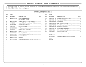
... number will be found on a label attached to the cabinet. NUMBER DESCRIPTION QTY KEY PART NO. NUMBER DESCRIPTION QTY 57 089037007700 Blade Guard Assembly (Inc. TABLE SAW - TABLE SAW or when ordering parts. Always mention the model number in all correspondence regarding your 10 in , Hex Hd 2 59 410162003 Screw (M6 x 18 mm, Cheese... 1 Not Shown: 987000864 Operator's Manual (089037008193 1 3-8-17 (Rev:04) 4 Key Nos. 51-56 1 58 080015001437 Screw (1/4-20 x 3-1/4 in . PARTS LIST FOR FIGURE A KEY PART NO. RYOBI 10 in.
... number will be found on a label attached to the cabinet. NUMBER DESCRIPTION QTY KEY PART NO. NUMBER DESCRIPTION QTY 57 089037007700 Blade Guard Assembly (Inc. TABLE SAW - TABLE SAW or when ordering parts. Always mention the model number in all correspondence regarding your 10 in , Hex Hd 2 59 410162003 Screw (M6 x 18 mm, Cheese... 1 Not Shown: 987000864 Operator's Manual (089037008193 1 3-8-17 (Rev:04) 4 Key Nos. 51-56 1 58 080015001437 Screw (1/4-20 x 3-1/4 in . PARTS LIST FOR FIGURE A KEY PART NO. RYOBI 10 in.
Parts Diagram
Page 6
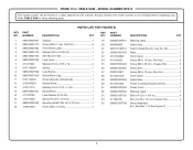
...M4 x 18 mm 4 19 089037007901 Warning Label 1 20 984406003 Switch Key 1 21 089110109712 Switch Assembly (Inc. PARTS LIST FOR FIGURE B KEY PART NO. TABLE SAW - MODEL NUMBER RTS10 The model number will be found on a label attached to the cabinet. Key No. 20 1 22 089037007044 Plate 1 23 0101040203 Cord Clamp... the model number in all correspondence regarding your 10 in 4 34 411062701 Nut (1/4-20 x 10 mm, Cheese Hd 4 35 089037007708 Stand Assembly (Inc. RYOBI 10 in. TABLE SAW or when ordering parts. Key Nos. 1-8, See Figure C 1 6
...M4 x 18 mm 4 19 089037007901 Warning Label 1 20 984406003 Switch Key 1 21 089110109712 Switch Assembly (Inc. PARTS LIST FOR FIGURE B KEY PART NO. TABLE SAW - MODEL NUMBER RTS10 The model number will be found on a label attached to the cabinet. Key No. 20 1 22 089037007044 Plate 1 23 0101040203 Cord Clamp... the model number in all correspondence regarding your 10 in 4 34 411062701 Nut (1/4-20 x 10 mm, Cheese Hd 4 35 089037007708 Stand Assembly (Inc. RYOBI 10 in. TABLE SAW or when ordering parts. Key Nos. 1-8, See Figure C 1 6
Parts Diagram
Page 7
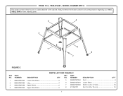
RYOBI 10 in . Always mention the model number in all correspondence regarding your 10 in . NUMBER DESCRIPTION QTY KEY PART NO. TABLE SAW or when ordering parts. 3 4 2 8 1 6 5 7 FIGURE C PARTS LIST FOR FIGURE C KEY PART NO. NUMBER DESCRIPTION QTY 1 089037007093 Lower Side Brace 2 2 089037007089 Leg 4 3 089037007088 Upper Brace 2 4 089037007090 ... (1/4-20 x 12 mm 16 8 411062701 Nut (1/4-20 x 10 mm 16 7 MODEL NUMBER RTS10 The model number will be found on a label attached to the cabinet. TABLE SAW -
RYOBI 10 in . Always mention the model number in all correspondence regarding your 10 in . NUMBER DESCRIPTION QTY KEY PART NO. TABLE SAW or when ordering parts. 3 4 2 8 1 6 5 7 FIGURE C PARTS LIST FOR FIGURE C KEY PART NO. NUMBER DESCRIPTION QTY 1 089037007093 Lower Side Brace 2 2 089037007089 Leg 4 3 089037007088 Upper Brace 2 4 089037007090 ... (1/4-20 x 12 mm 16 8 411062701 Nut (1/4-20 x 10 mm 16 7 MODEL NUMBER RTS10 The model number will be found on a label attached to the cabinet. TABLE SAW -
Parts Diagram
Page 8
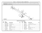
RYOBI 10 in . Always mention the model number in all correspondence regarding your 10 in . NUMBER DESCRIPTION QTY KEY PART NO. MODEL NUMBER RTS10 The model number will be found on a label attached to the cabinet. TABLE SAW or when ordering parts. FIGURE D 17 15 14 16 13... 12 11 10 9 8 7 5 46 3 1 2 PARTS LIST FOR FIGURE D KEY PART NO. TABLE SAW - NUMBER DESCRIPTION QTY 1 089037007080 Locking Lever 1 2 089037007081 Screw (M8 x 5/8 in 2 3 089037007082 Lock Rod 1 4 089037007083 Handle Bar 1 5 414011028...
RYOBI 10 in . Always mention the model number in all correspondence regarding your 10 in . NUMBER DESCRIPTION QTY KEY PART NO. MODEL NUMBER RTS10 The model number will be found on a label attached to the cabinet. TABLE SAW or when ordering parts. FIGURE D 17 15 14 16 13... 12 11 10 9 8 7 5 46 3 1 2 PARTS LIST FOR FIGURE D KEY PART NO. TABLE SAW - NUMBER DESCRIPTION QTY 1 089037007080 Locking Lever 1 2 089037007081 Screw (M8 x 5/8 in 2 3 089037007082 Lock Rod 1 4 089037007083 Handle Bar 1 5 414011028...
Parts Diagram
Page 9
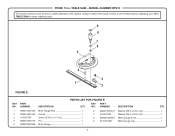
... QTY 1 089015001009 Miter Gauge Rod 1 2 080015001563 Pointer 1 3 410332701 Screw (3/16 in . TABLE SAW or when ordering parts. 9 8 7 6 5 4 FIGURE E 3 1 2 PARTS LIST FOR FIGURE E KEY PART NO. MODEL NUMBER RTS10 The model number will be found on a label attached to the cabinet. RYOBI 10 in . Always mention the model number in all correspondence regarding your...
... QTY 1 089015001009 Miter Gauge Rod 1 2 080015001563 Pointer 1 3 410332701 Screw (3/16 in . TABLE SAW or when ordering parts. 9 8 7 6 5 4 FIGURE E 3 1 2 PARTS LIST FOR FIGURE E KEY PART NO. MODEL NUMBER RTS10 The model number will be found on a label attached to the cabinet. RYOBI 10 in . Always mention the model number in all correspondence regarding your...
Parts Diagram
Page 10
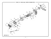
MODEL NUMBER RTS10 25 24 22 23 10 9 13 3 12 11 8 7 6 15 14 19 18 16 17 21 21 20 1 2 3 SECTION "A" 4 5 10 12 26 TABLE SAW - RYOBI 10 in.
MODEL NUMBER RTS10 25 24 22 23 10 9 13 3 12 11 8 7 6 15 14 19 18 16 17 21 21 20 1 2 3 SECTION "A" 4 5 10 12 26 TABLE SAW - RYOBI 10 in.
Parts Diagram
Page 11
MODEL NUMBER RTS10 The model number will be found on a label attached to the system, service should be performed by your nearest Ryobi Authorized Service Center. NUMBER DESCRIPTION QTY 1 0101010807 Screw w/Washer (M5 x 30 mm 1 2 0121010242 Wire Clamp 1 3 410272004 Screw ... Bearing (6201 ZZ C3 1 20 410174721 Screw (8-32 x 3/8 in . TABLE SAW - NUMBER DESCRIPTION QTY KEY PART NO. To avoid the possibility of the double insulated system. TABLE SAW or when ordering parts. RYOBI 10 in , Truss Hd 1 21 412042002 Lock Washer (D4 2 22 089037007055...
MODEL NUMBER RTS10 The model number will be found on a label attached to the system, service should be performed by your nearest Ryobi Authorized Service Center. NUMBER DESCRIPTION QTY 1 0101010807 Screw w/Washer (M5 x 30 mm 1 2 0121010242 Wire Clamp 1 3 410272004 Screw ... Bearing (6201 ZZ C3 1 20 410174721 Screw (8-32 x 3/8 in . TABLE SAW - NUMBER DESCRIPTION QTY KEY PART NO. To avoid the possibility of the double insulated system. TABLE SAW or when ordering parts. RYOBI 10 in , Truss Hd 1 21 412042002 Lock Washer (D4 2 22 089037007055...

