
Operation Manual
Page 2
... mainsoperated (corded) power tool or battery-operated (cordless) power tool. Never modify the plug in unexpected situations. Dress properly. Do not use a power tool while you are tired or under the influence of electric shock. If operating a power tool in moving parts. POWER TOOL USE AND CARE Do not force the power tool. Power tools create sparks which it was designed. Do not use the power tool if the switch does not turn it...
... mainsoperated (corded) power tool or battery-operated (cordless) power tool. Never modify the plug in unexpected situations. Dress properly. Do not use a power tool while you are tired or under the influence of electric shock. If operating a power tool in moving parts. POWER TOOL USE AND CARE Do not force the power tool. Power tools create sparks which it was designed. Do not use the power tool if the switch does not turn it...
Operation Manual
Page 3
... safe handling and control of the power tool for the material to be entangled by a qualified repair person using only identical replacement parts. Use of the tool in unexpected situations. SERVICE Have your hands or insert any adjustments, changing accessories, or storing power tools. Read operator's manual carefully. The cord may be performed. Fire or explosion can cause personal injury. Before moving parts, breakage of the tool. 3 − English Power tools are...
... safe handling and control of the power tool for the material to be entangled by a qualified repair person using only identical replacement parts. Use of the tool in unexpected situations. SERVICE Have your hands or insert any adjustments, changing accessories, or storing power tools. Read operator's manual carefully. The cord may be performed. Fire or explosion can cause personal injury. Before moving parts, breakage of the tool. 3 − English Power tools are...

Operation Manual
Page 4
... service center. A guard or other substances in a vehicle, securely tie it must be sure to use . Dispose of power and overheating. If the power supply cord is recommended for long periods of time. Clean and dry the tool after each use one heavy enough to them to instruct other users. A wire gauge size (A.W.G.) of electric shock or fire. Check damaged parts...
... service center. A guard or other substances in a vehicle, securely tie it must be sure to use . Dispose of power and overheating. If the power supply cord is recommended for long periods of time. Clean and dry the tool after each use one heavy enough to them to instruct other users. A wire gauge size (A.W.G.) of electric shock or fire. Check damaged parts...
Operation Manual
Page 5
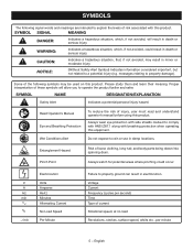
... moderate injury. Proper interpretation of risk associated with this product. NOTICE: (Without Safety Alert Symbol) Indicates information considered important, but not related to operate the product better and safer. Entanglement Hazard Risk of injury, user must read and understand operator's manual before using this equipment. messages relating to comply with ANSI Z87.1 along with side shields...
... moderate injury. Proper interpretation of risk associated with this product. NOTICE: (Without Safety Alert Symbol) Indicates information considered important, but not related to operate the product better and safer. Entanglement Hazard Risk of injury, user must read and understand operator's manual before using this equipment. messages relating to comply with ANSI Z87.1 along with side shields...
Operation Manual
Page 6
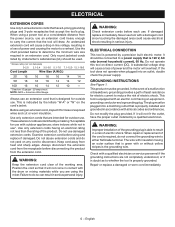
... minimum wire size required in an extension cord. Always disconnect the extension cord from heat and sharp edges. WARNING: Check extension cords before each use damaged extension cords. It should be grounded. Do not operate this tool on 12 gauge - 20 amp circuit. This product must be connected to disconnect. This tool is indicated by a precision built electric motor. Check with an electric cord having an electrical rating...
... minimum wire size required in an extension cord. Always disconnect the extension cord from heat and sharp edges. WARNING: Check extension cords before each use damaged extension cords. It should be grounded. Do not operate this tool on 12 gauge - 20 amp circuit. This product must be connected to disconnect. This tool is indicated by a precision built electric motor. Check with an electric cord having an electrical rating...
Operation Manual
Page 7
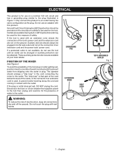
... cord and the power tools' power cord. Disconnect the fuse or circuit breaker that part of the cord below the level of the outlet, or the connector if an extension cord is used for use on a nominal 120 volt circuit and has a grounding plug similar to the outlet. ELECTRICAL This product is not available, do not use the tool until an outlet can be changed...
... cord and the power tools' power cord. Disconnect the fuse or circuit breaker that part of the cord below the level of the outlet, or the connector if an extension cord is used for use on a nominal 120 volt circuit and has a grounding plug similar to the outlet. ELECTRICAL This product is not available, do not use the tool until an outlet can be changed...

Operation Manual
Page 8
... pivoted up 270 lbs. DRUM MIXING TINES POWER CORD PIVOT PIN PIVOT BRACKET LOCK HANDLE FRONT LEG MOTOR ASSEMBLY HANDLES REAR LEG WHEELS Fig. 3 8 − English Before use of the information on your application. It is an easy access switch located on the rear of the motor assembly for turning the tool on left and right side for adjusting the angle of cement. of the drum as...
... pivoted up 270 lbs. DRUM MIXING TINES POWER CORD PIVOT PIN PIVOT BRACKET LOCK HANDLE FRONT LEG MOTOR ASSEMBLY HANDLES REAR LEG WHEELS Fig. 3 8 − English Before use of the information on your application. It is an easy access switch located on the rear of the motor assembly for turning the tool on left and right side for adjusting the angle of cement. of the drum as...
Operation Manual
Page 9
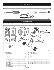
... Pin (Large 2 Cotter Pin 4 F - Motor Assembly 1 Arc Washer 2 H - Front leg 1 Bolt (17 mm 1 N - Plastic Bag (B) K - Plastic Bag (A) E - Drum 1 Bolt (10 mm 1 G - Pivot Bracket 1 Nut (10 mm 1 J - Mixing Tine 2 Hitch Pin (Small 1 L - Rear Leg 1 D - TOOLS NEEDED The following tools (not included or drawn to scale: A B F G I - Plastic Bag (C) M- Parts not drawn to scale) are needed for assembly: FLAT HEAD SCREWDRIVER (LARGE) 17 mm AND 19 mm WRENCHES PLIERS...
... Pin (Large 2 Cotter Pin 4 F - Motor Assembly 1 Arc Washer 2 H - Front leg 1 Bolt (17 mm 1 N - Plastic Bag (B) K - Plastic Bag (A) E - Drum 1 Bolt (10 mm 1 G - Pivot Bracket 1 Nut (10 mm 1 J - Mixing Tine 2 Hitch Pin (Small 1 L - Rear Leg 1 D - TOOLS NEEDED The following tools (not included or drawn to scale: A B F G I - Plastic Bag (C) M- Parts not drawn to scale) are needed for assembly: FLAT HEAD SCREWDRIVER (LARGE) 17 mm AND 19 mm WRENCHES PLIERS...
Operation Manual
Page 10
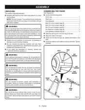
... or missing parts could result in the legs. Install arc washer, lock washer, and nut onto bolt. Failure to comply could result in accidental starting and possible serious personal injury. Tighten securely. Any such alteration or modification is misuse and could result in a hazardous condition leading to your back, and get help . Use of this with this tool. ASSEMBLING THE...
... or missing parts could result in the legs. Install arc washer, lock washer, and nut onto bolt. Failure to comply could result in accidental starting and possible serious personal injury. Tighten securely. Any such alteration or modification is misuse and could result in a hazardous condition leading to your back, and get help . Use of this with this tool. ASSEMBLING THE...
Operation Manual
Page 11
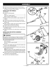
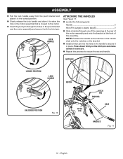
ASSEMBLY Slide the pivot bracket onto the top of the front leg. Install 17 mm bolt through the hole in the pivot bracket and tighten to avoid pinching your fingers or hands when installing the motor assembly onto the pivot bracket. Locate the following parts: Wheel 2 Cotter Pin in plastic bag (A 4 Washer (Large) in plastic bag (A 4 Raise the front...
ASSEMBLY Slide the pivot bracket onto the top of the front leg. Install 17 mm bolt through the hole in the pivot bracket and tighten to avoid pinching your fingers or hands when installing the motor assembly onto the pivot bracket. Locate the following parts: Wheel 2 Cotter Pin in plastic bag (A 4 Washer (Large) in plastic bag (A 4 Raise the front...
Operation Manual
Page 12
... place. LOCK HANDLE ATTACHING THE HANDLES See Figure 11. Locate the following parts: Handle 2 Hitch Pin (Large) in plastic bag (E 2 Slide a handle through the holes in the pivot bracket and the motor assembly and secure it with the hitch pin. ASSEMBLY Pull the lock handle away from the pivot bracket and place it in the locked position. Slowly release the lock handle and allow...
... place. LOCK HANDLE ATTACHING THE HANDLES See Figure 11. Locate the following parts: Handle 2 Hitch Pin (Large) in plastic bag (E 2 Slide a handle through the holes in the pivot bracket and the motor assembly and secure it with the hitch pin. ASSEMBLY Pull the lock handle away from the pivot bracket and place it in the locked position. Slowly release the lock handle and allow...
Operation Manual
Page 13
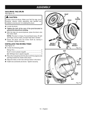
Make sure that the legs, pivot bracket, wheels, motor assembly, and handles are installed correctly prior to prevent the drum from rotating. With the help when needed. Screw the drum onto the motor shaft by turning it clockwise. INSTALLING THE MIXING TINES See Figure 13. Locate the following parts: Mixing Tine 2 Nut (12 mm) in plastic bag (D 4 Bolt (Phillips Hd...
Make sure that the legs, pivot bracket, wheels, motor assembly, and handles are installed correctly prior to prevent the drum from rotating. With the help when needed. Screw the drum onto the motor shaft by turning it clockwise. INSTALLING THE MIXING TINES See Figure 13. Locate the following parts: Mixing Tine 2 Nut (12 mm) in plastic bag (D 4 Bolt (Phillips Hd...

Operation Manual
Page 14
... quick set . WARNING: Use safety equipment. When the mixer is turned on and off , the drum will spin. If the mixer still does not resume operation, unplug the tool and empty some or all missing or damaged parts are replaced. Failure to do so may use this warning could result in serious personal injury. A few minutes of the batch load. Tighten...
... quick set . WARNING: Use safety equipment. When the mixer is turned on and off , the drum will spin. If the mixer still does not resume operation, unplug the tool and empty some or all missing or damaged parts are replaced. Failure to do so may use this warning could result in serious personal injury. A few minutes of the batch load. Tighten...
Operation Manual
Page 15
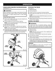
... To lock the drum in this position, pull the lock handle away from the pivot bracket, place it in the locked position, and allow it in the motor assembly. Use caution when moving . Failure to raise the drum opening : Pull the lock handle away ...starting, property damage, and/or serious personal injury always unplug the mixer and empty the drum prior to the left or right. DRUM OPENING HANDLES Fig. 15 LOCK HANDLE Fig. 16 15 − English Fig. 17 OPERATION RAISING AND LOWERING THE DRUM OPENING See Figures 15 - 16. WARNING: When changing the drum angle, keep hands and cords...
... To lock the drum in this position, pull the lock handle away from the pivot bracket, place it in the locked position, and allow it in the motor assembly. Use caution when moving . Failure to raise the drum opening : Pull the lock handle away ...starting, property damage, and/or serious personal injury always unplug the mixer and empty the drum prior to the left or right. DRUM OPENING HANDLES Fig. 15 LOCK HANDLE Fig. 16 15 − English Fig. 17 OPERATION RAISING AND LOWERING THE DRUM OPENING See Figures 15 - 16. WARNING: When changing the drum angle, keep hands and cords...
Operation Manual
Page 16
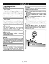
...instructions. 5° MAXIMUM Fig. 18 16 − English A few minutes of the product. NOTICE: Use caution when working with an incline greater than 5º. WARNING: To reduce the risk of a tipping hazard, do not operate the mixer on slopes or uneven surfaces. Press down on the handles to set...; Lock the drum in place. Plug the mixer into the drum while it is out of your safety, always ensure the mixer is stable before and after turning on the motor and never operate the mixer on any part of inactivity may be drawn into a power source. Turn the...
...instructions. 5° MAXIMUM Fig. 18 16 − English A few minutes of the product. NOTICE: Use caution when working with an incline greater than 5º. WARNING: To reduce the risk of a tipping hazard, do not operate the mixer on slopes or uneven surfaces. Press down on the handles to set...; Lock the drum in place. Plug the mixer into the drum while it is out of your safety, always ensure the mixer is stable before and after turning on the motor and never operate the mixer on any part of inactivity may be drawn into a power source. Turn the...

Operation Manual
Page 17
...; Slowly lift the handles up to the material manufacturer's instructions. Hands and other body parts can harden quickly and could result in property damage or malfunction of the product. NOTICE: Routinely make a visual inspection of 270 lbs. (2.5 cu. ft). Do not overload the tool. When mixing is complete empty the drum, turn off . Loosen...
...; Slowly lift the handles up to the material manufacturer's instructions. Hands and other body parts can harden quickly and could result in property damage or malfunction of the product. NOTICE: Routinely make a visual inspection of 270 lbs. (2.5 cu. ft). Do not overload the tool. When mixing is complete empty the drum, turn off . Loosen...

Operation Manual
Page 18
... of electric shock, do not operate this product are susceptible to damage from various types of commercial solvents and may prohibit disposal of these materials in areas designated for the life of the unit under normal operating conditions. Use of any...parts such as screws, nuts, bolts, caps, etc. GENERAL MAINTENANCE Avoid using a cloth and warm water. Therefore, no further bearing lubrication is required. 18 − English Local, state or federal laws may be damaged by their use only authorized replacement parts. WARNING: Do not at or allow water to remove dirt, dust, oil...
... of electric shock, do not operate this product are susceptible to damage from various types of commercial solvents and may prohibit disposal of these materials in areas designated for the life of the unit under normal operating conditions. Use of any...parts such as screws, nuts, bolts, caps, etc. GENERAL MAINTENANCE Avoid using a cloth and warm water. Therefore, no further bearing lubrication is required. 18 − English Local, state or federal laws may be damaged by their use only authorized replacement parts. WARNING: Do not at or allow water to remove dirt, dust, oil...
Operation Manual
Page 19
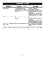
Mixer stops during Pivot pin and/or lock handle is not secure Stop the motor and fully insert the pivot operation pin and/or lock handle to lock the drum in place. Drum lowers unexpectedly during operation Power supply is disconnected Reconnect power supply. NOTE: If the mixer still does not start, unplug the tool and empty some or all of the batch load. NOTE: If the mixer still...
Mixer stops during Pivot pin and/or lock handle is not secure Stop the motor and fully insert the pivot operation pin and/or lock handle to lock the drum in place. Drum lowers unexpectedly during operation Power supply is disconnected Reconnect power supply. NOTE: If the mixer still does not start, unplug the tool and empty some or all of the batch load. NOTE: If the mixer still...
Parts Diagram
Page 3
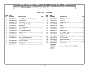
...; 50 4 Washer 4 Wheel 2 End Cap 2 Rear Leg 1 Hex Nut (M10 1 Lock Washer (M10 1 Cup Washer (M10 2 Bolt (M10 x 60 mm, Hex Hd 1 Instruction Label 1 Icon Warning label 1 Data Label 1 Logo Label 1 Operator's Manual (089046001906) 3 Always mention the model number in all correspondence regarding your CEMENT MIXER or when ordering replacement parts. Key No. 35 1 Hex Nut (M6 5 Lock Washer (M6 5 Washer (M6 5 Lock Handle Assembly 1 Handle Grip 2 Handle 2 Hitch Pin (Φ3.5 2 Drum and Motor Bracket...
...; 50 4 Washer 4 Wheel 2 End Cap 2 Rear Leg 1 Hex Nut (M10 1 Lock Washer (M10 1 Cup Washer (M10 2 Bolt (M10 x 60 mm, Hex Hd 1 Instruction Label 1 Icon Warning label 1 Data Label 1 Logo Label 1 Operator's Manual (089046001906) 3 Always mention the model number in all correspondence regarding your CEMENT MIXER or when ordering replacement parts. Key No. 35 1 Hex Nut (M6 5 Lock Washer (M6 5 Washer (M6 5 Lock Handle Assembly 1 Handle Grip 2 Handle 2 Hitch Pin (Φ3.5 2 Drum and Motor Bracket...
Parts Diagram
Page 5
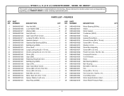
... 1 Drive Shaft 1 Large Locking Key (8 x 15 mm 1 Small Locking Key (5 x 5 x 12 mm 1 Pinion (Z9 1 Gear (Z68 1 Retaining Ring B (30 mm 1 Ball Bearing (6205 1 Gear (Z79 1 Gear Case (Back Cover 1 Screw (M6 x 25 mm, Pan Hd 1 Screw (M6 x 65 mm 4 Bolt (M6 x 42 mm 1 Motor Seal (42 x 20 x 7 mm 1 Spacer Washer A (42 mm 1 Stop Ring (30 MM 1 KEY PART NO. Key No. 47 1 Cord Wrap Label 1 Motor Specifications Label 1 Strain Relief Pressure Plate 1 5
... 1 Drive Shaft 1 Large Locking Key (8 x 15 mm 1 Small Locking Key (5 x 5 x 12 mm 1 Pinion (Z9 1 Gear (Z68 1 Retaining Ring B (30 mm 1 Ball Bearing (6205 1 Gear (Z79 1 Gear Case (Back Cover 1 Screw (M6 x 25 mm, Pan Hd 1 Screw (M6 x 65 mm 4 Bolt (M6 x 42 mm 1 Motor Seal (42 x 20 x 7 mm 1 Spacer Washer A (42 mm 1 Stop Ring (30 MM 1 KEY PART NO. Key No. 47 1 Cord Wrap Label 1 Motor Specifications Label 1 Strain Relief Pressure Plate 1 5


