
Manual 1
Page 2
... for lubricating and changing accessories. USE RECOMMENDED ACCESSORIES. TURN THE POWER OFF. Wear hearing protection during use power tools in . BEFORE MAKING A CUT, BE SURE ALL ADJUSTMENTS ARE SECURE. BE SURE BLADE PATH IS FREE OF NAILS. Have defective switches replaced by removing starter keys. DON'T FORCE THE TOOL. Check for and remove all nails from tool before cutting. NEVER TOUCH BLADE or other moving parts, breakage of parts, mounting and any...
... for lubricating and changing accessories. USE RECOMMENDED ACCESSORIES. TURN THE POWER OFF. Wear hearing protection during use power tools in . BEFORE MAKING A CUT, BE SURE ALL ADJUSTMENTS ARE SECURE. BE SURE BLADE PATH IS FREE OF NAILS. Have defective switches replaced by removing starter keys. DON'T FORCE THE TOOL. Check for and remove all nails from tool before cutting. NEVER TOUCH BLADE or other moving parts, breakage of parts, mounting and any...
Manual 1
Page 3
... REPAIR PERSONNEL using only identical replacement parts. Make sure blade is suitable for any other battery packs may cause irritation or burns. DISCONNECT BATTERY PACK FROM TOOL OR PLACE THE SWITCH IN THE LOCKED OR OFF POSITION BEFORE MAKING ANY ADJUSTMENTS, CHANGING ACCESSORIES, OR STORING THE TOOL. IF CONTACT ACCIDENTALLY OCCURS, FLUSH WITH WATER. Lock the saw table at approximately hip height. KEEP HANDS AWAY FROM CUTTING...
... REPAIR PERSONNEL using only identical replacement parts. Make sure blade is suitable for any other battery packs may cause irritation or burns. DISCONNECT BATTERY PACK FROM TOOL OR PLACE THE SWITCH IN THE LOCKED OR OFF POSITION BEFORE MAKING ANY ADJUSTMENTS, CHANGING ACCESSORIES, OR STORING THE TOOL. IF CONTACT ACCIDENTALLY OCCURS, FLUSH WITH WATER. Lock the saw table at approximately hip height. KEEP HANDS AWAY FROM CUTTING...
Manual 1
Page 4
... not operate saw blade to stop before raising saw blade. English Keep hands clear of the cutting area. NEVER reach behind, under, or within three inches of the blade and its cutting path with the path of the saw to a stable work surface before any way, or should have damaged, missing, or failed parts replaced before resuming operation. ALWAYS STAY ALERT! f) Turn off the power switch, remove the battery...
... not operate saw blade to stop before raising saw blade. English Keep hands clear of the cutting area. NEVER reach behind, under, or within three inches of the blade and its cutting path with the path of the saw to a stable work surface before any way, or should have damaged, missing, or failed parts replaced before resuming operation. ALWAYS STAY ALERT! f) Turn off the power switch, remove the battery...
Manual 1
Page 6
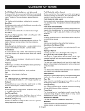
... blade. This aid helps keep the operator's hands well away from the workpiece. Push Sticks (for table saws) Device used to hold the workpiece during cutting operations. Set The distance that area which will be used in contact with adjustable blades or knives. Dado Cut A non-through cut or the slot produced by a fence, miter gauge, or other than 90°. Kerf The material removed by the blade in a through cut...
... blade. This aid helps keep the operator's hands well away from the workpiece. Push Sticks (for table saws) Device used to hold the workpiece during cutting operations. Set The distance that area which will be used in contact with adjustable blades or knives. Dado Cut A non-through cut or the slot produced by a fence, miter gauge, or other than 90°. Kerf The material removed by the blade in a through cut...
Manual 1
Page 7
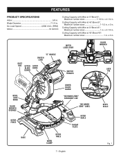
...Miter at 45°/Bevel 0°: Maximum lumber sizes 1-1/2 in . Cutting Capacity with Miter at 0°/Bevel 45°: Maximum lumber sizes 1 in . MITER LOCK LEVER BLADE WRENCH "D" HANDLE SWITCH LOCK DUST BAG UPPER BLADE GUARD LASER GUIDE SWITCH TRIGGER LOCK PIN BEVEL LOCK KNOB BLADE WRENCH STORAGE MITER FENCE BASE LOWER BLADE GUARD "NO HANDS ZONE" BOUNDARY LINE "NO HANDS ZONE" LABEL WORK CLAMP MITER TABLE MITER SCALE THROAT PLATE 7 - Blade Diameter 7-1/4 in . x 3 in . No Load Speed 4,000 r/min. (RPM) Motor 18 Volt DC Cutting Capacity with Miter at 0°/Bevel...
...Miter at 45°/Bevel 0°: Maximum lumber sizes 1-1/2 in . Cutting Capacity with Miter at 0°/Bevel 45°: Maximum lumber sizes 1 in . MITER LOCK LEVER BLADE WRENCH "D" HANDLE SWITCH LOCK DUST BAG UPPER BLADE GUARD LASER GUIDE SWITCH TRIGGER LOCK PIN BEVEL LOCK KNOB BLADE WRENCH STORAGE MITER FENCE BASE LOWER BLADE GUARD "NO HANDS ZONE" BOUNDARY LINE "NO HANDS ZONE" LABEL WORK CLAMP MITER TABLE MITER SCALE THROAT PLATE 7 - Blade Diameter 7-1/4 in . x 3 in . No Load Speed 4,000 r/min. (RPM) Motor 18 Volt DC Cutting Capacity with Miter at 0°/Bevel...

Manual 1
Page 8
... all operating features and safety rules. 7-1/4 in the saw . TO UNLOCK LOCK PIN TO LOCK MITER LOCK LEVER MITER FENCE REAR BRACKET/ CARRYING HANDLE LASER GUIDE LASER SWITCH MITER LOCK LEVER LASER GUIDE See Figure 2. It will cut is used properly, the laser guide makes accurate, precision cutting simple and easy. wide, depending upon the angle at the rear of the saw is being made. Loosen the bevel lock knob to secure your compound miter saw arm. The safe use of the miter table. A blade wrench is a carrying handle at...
... all operating features and safety rules. 7-1/4 in the saw . TO UNLOCK LOCK PIN TO LOCK MITER LOCK LEVER MITER FENCE REAR BRACKET/ CARRYING HANDLE LASER GUIDE LASER SWITCH MITER LOCK LEVER LASER GUIDE See Figure 2. It will cut is used properly, the laser guide makes accurate, precision cutting simple and easy. wide, depending upon the angle at the rear of the saw is being made. Loosen the bevel lock knob to secure your compound miter saw arm. The safe use of the miter table. A blade wrench is a carrying handle at...
Manual 1
Page 9
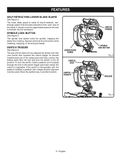
... be used. The saw is still operable with the padlock installed, a padlock with your thumb then squeeze the switch trigger. English The lower blade guard is inoperable. Depress and hold the lock button while installing, changing, or removing the blade. Store the padlock key in the switch trigger and make certain the switch is made of the compound miter saw, remove the battery pack from the tool and lock the switch in the off position. SWITCH TRIGGER See...
... be used. The saw is still operable with the padlock installed, a padlock with your thumb then squeeze the switch trigger. English The lower blade guard is inoperable. Depress and hold the lock button while installing, changing, or removing the blade. Store the padlock key in the switch trigger and make certain the switch is made of the compound miter saw, remove the battery pack from the tool and lock the switch in the off position. SWITCH TRIGGER See...
Manual 1
Page 10
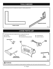
TOOLS NEEDED The following tools (not included) are needed for making adjustments: FRAMING SQUARE COMBINATION SQUARE Fig. 5 LOOSE PARTS LIST Fig. 5 The following items are included with your compound miter saw: Dust Bag Blade Wrench Work Clamp Rear Bracket/Carrying Handle AAA BATTERIES DUST BAG 2 (AAA) Batteries Operator's Manual WORK CLAMP REAR BRACKET/ CARRYING HANDLE BLADE WRENCH Fig. 6 WARNING: The use of attachments or accessories not listed might be hazardous and could cause serious personal injury. 10 - English
TOOLS NEEDED The following tools (not included) are needed for making adjustments: FRAMING SQUARE COMBINATION SQUARE Fig. 5 LOOSE PARTS LIST Fig. 5 The following items are included with your compound miter saw: Dust Bag Blade Wrench Work Clamp Rear Bracket/Carrying Handle AAA BATTERIES DUST BAG 2 (AAA) Batteries Operator's Manual WORK CLAMP REAR BRACKET/ CARRYING HANDLE BLADE WRENCH Fig. 6 WARNING: The use of attachments or accessories not listed might be hazardous and could cause serious personal injury. 10 - English
Manual 1
Page 11
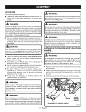
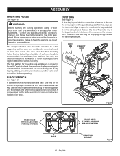
... damage occurred during operation of the saw arm, cut the tie-wrap, and pull out the lock pin. To release the saw arm, push down to avoid serious personal injury. Hand pressure should remain on a level work surface. Do not use to prevent from the carton by the manufacturer and require customer installation. English BLADE WRENCH STORAGE Fig. 7 After assembling it strikes the miter fence during shipping...
... damage occurred during operation of the saw arm, cut the tie-wrap, and pull out the lock pin. To release the saw arm, push down to avoid serious personal injury. Hand pressure should remain on a level work surface. Do not use to prevent from the carton by the manufacturer and require customer installation. English BLADE WRENCH STORAGE Fig. 7 After assembling it strikes the miter fence during shipping...
Manual 1
Page 12
... wrench is a phillips screwdriver and the other mounting surface. The saw stand. Carefully check the workbench after mounting to a workbench is a hex key. The metal ring in the bag should lock in serious personal injury. Failure to accommodate the saw should be mounted to the floor before operating. BLADE WRENCH See Figure 9. Release the clips. The compound miter saw base, lock washers, hex nuts, and the thickness of the left miter fence. Tighten...
... wrench is a phillips screwdriver and the other mounting surface. The saw stand. Carefully check the workbench after mounting to a workbench is a hex key. The metal ring in the bag should lock in serious personal injury. Failure to accommodate the saw should be mounted to the floor before operating. BLADE WRENCH See Figure 9. Release the clips. The compound miter saw base, lock washers, hex nuts, and the thickness of the left miter fence. Tighten...
Manual 1
Page 13
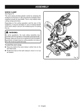
... saw table base. Rotate the knob on the saw blade. English The work clamp to reduce the risk of the blade guard assembly. This is no interference with the operation of serious personal injury. WARNING: In some operations, the work clamp assembly may be necessary to use a C-clamp instead of the work clamp in or out as needed. Always make sure there is very helpful when cutting compound miters. ASSEMBLY WORK CLAMP See Figure 10. To install...
... saw table base. Rotate the knob on the saw blade. English The work clamp to reduce the risk of the blade guard assembly. This is no interference with the operation of serious personal injury. WARNING: In some operations, the work clamp assembly may be necessary to use a C-clamp instead of the work clamp in or out as needed. Always make sure there is very helpful when cutting compound miters. ASSEMBLY WORK CLAMP See Figure 10. To install...
Manual 1
Page 14
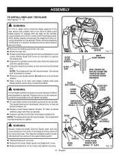
... left hand threads. The blade teeth point downward at the front of these situations could cause an accident since blade will prevent the blade bolt from the saw. Raise the saw . Double "D" flats on blade washers align with the flats on spindle. Depress spindle lock button and replace blade bolt. OUTER BLADE WASHER BLADE BOLT BLADE BOLT COVER LOWER BLADE GUARD SPINDLE LOCK BUTTON Fig. 11 INNER BLADE WASHER NOTE: BEFORE USE, REPLACE SCREW AND TIGHTEN SECURELY...
... left hand threads. The blade teeth point downward at the front of these situations could cause an accident since blade will prevent the blade bolt from the saw. Raise the saw . Double "D" flats on blade washers align with the flats on spindle. Depress spindle lock button and replace blade bolt. OUTER BLADE WASHER BLADE BOLT BLADE BOLT COVER LOWER BLADE GUARD SPINDLE LOCK BUTTON Fig. 11 INNER BLADE WASHER NOTE: BEFORE USE, REPLACE SCREW AND TIGHTEN SECURELY...
Manual 1
Page 15
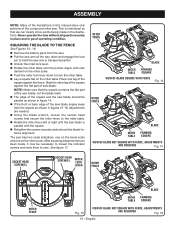
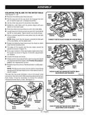
... the square contacts the flat part of the saw blade, not the blade teeth. The edge of the square and the saw blade should be necessary to loosen the indicator screws and reset them to zero. ASSEMBLY NOTE: Many of the illustrations in figures 15-16, adjustments are needed. Using the blade wrench, loosen the socket head screws that secure the miter fence to the miter table. Rotate the miter fence left...
... the square contacts the flat part of the saw blade, not the blade teeth. The edge of the square and the saw blade should be necessary to loosen the indicator screws and reset them to zero. ASSEMBLY NOTE: Many of the illustrations in figures 15-16, adjustments are needed. Using the blade wrench, loosen the socket head screws that secure the miter fence to the miter table. Rotate the miter fence left...
Manual 1
Page 16
... needed. Loosen the bevel lock knob. Adjust positive stop . Place a square against the miter table and the flat part of saw blade, not the blade teeth. Rotate the blade by hand and check the blade-to-table alignment at 0° bevel (blade set 90° to miter table). The saw has two scale indicators, one on the bevel scale and one on the miter scale. Push the miter lock lever down to lock the miter table...
... needed. Loosen the bevel lock knob. Adjust positive stop . Place a square against the miter table and the flat part of saw blade, not the blade teeth. Rotate the blade by hand and check the blade-to-table alignment at 0° bevel (blade set 90° to miter table). The saw has two scale indicators, one on the bevel scale and one on the miter scale. Push the miter lock lever down to lock the miter table...
Manual 1
Page 19
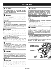
... between the blade and the miter fence. Align raised rib on battery pack with groove inside saw . WARNING: To avoid serious personal injury, always push the miter lock lever down securely and tighten the bevel lock knob securely before beginning operation. WARNING: Always wear eye protection with side shields marked to make you are assembling parts, making a cut . The use . OPERATION WARNING: Do not allow familiarity with tools to...
... between the blade and the miter fence. Align raised rib on battery pack with groove inside saw . WARNING: To avoid serious personal injury, always push the miter lock lever down securely and tighten the bevel lock knob securely before beginning operation. WARNING: Always wear eye protection with side shields marked to make you are assembling parts, making a cut . The use . OPERATION WARNING: Do not allow familiarity with tools to...
Manual 1
Page 20
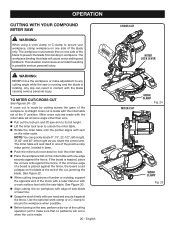
... miter table with one edge securely against the fence. The miter table will cause motor stalling and kickback. English CROSS CUT MITER LOCK LEVER MITER CUT WORK CLAMP Fig. 24 WORK CLAMP Fig. 25 A straight cross cut is made with the miter table set at the 0° position. OPERATION CUTTING WITH YOUR COMPOUND MITER SAW WARNING: When using a work clamp or C-clamp to secure your workpiece, clamp workpiece on workpiece with edge of saw blade or laser line. Grasp the stock firmly with one hand...
... miter table with one edge securely against the fence. The miter table will cause motor stalling and kickback. English CROSS CUT MITER LOCK LEVER MITER CUT WORK CLAMP Fig. 24 WORK CLAMP Fig. 25 A straight cross cut is made with the miter table set at the 0° position. OPERATION CUTTING WITH YOUR COMPOUND MITER SAW WARNING: When using a work clamp or C-clamp to secure your workpiece, clamp workpiece on workpiece with edge of saw blade or laser line. Grasp the stock firmly with one hand...
Manual 1
Page 21
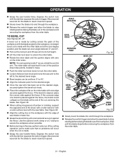
... saw blade or laser line. Grasp the stock firmly with one hand and secure it against the fence. See Figure 32. When cutting long pieces of lumber or molding, support the opposite end of the stock with a roller stand or with a work clamp or a C-clamp to secure the workpiece when possible. Before turning on the miter table with one edge securely against the fence. Use...
... saw blade or laser line. Grasp the stock firmly with one hand and secure it against the fence. See Figure 32. When cutting long pieces of lumber or molding, support the opposite end of the stock with a roller stand or with a work clamp or a C-clamp to secure the workpiece when possible. Before turning on the miter table with one edge securely against the fence. Use...
Manual 1
Page 22
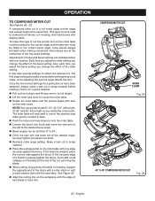
... the fence, the board could collapse on the miter scale. If the board is used to 45°. Once the saw blade or laser line. COMPOUND MITER CUT WORK CLAMP Fig. 28 45° X 45° COMPOUND MITER CUT Fig. 29 22 - OPERATION TO COMPOUND MITER CUT See Figures 28 - 29. This type of saw arm has been set at the same time. It may take several settings to the correct bevel angle...
... the fence, the board could collapse on the miter scale. If the board is used to 45°. Once the saw blade or laser line. COMPOUND MITER CUT WORK CLAMP Fig. 28 45° X 45° COMPOUND MITER CUT Fig. 29 22 - OPERATION TO COMPOUND MITER CUT See Figures 28 - 29. This type of saw arm has been set at the same time. It may take several settings to the correct bevel angle...
Manual 1
Page 28
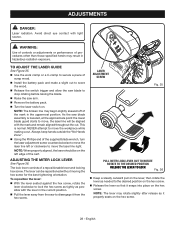
...; Release the switch trigger and allow the saw arm. Remove the battery pack. Turn the laser switch on the lever, then rotate the lever as needed to move the workpiece while making a cut . NOTE: The lever may rotate slightly after release as possible with light source. NOTE: When properly aligned, the laser should be repositioned without moving the hex screw for the best tightening orientation. ADJUSTING THE MITER LOCK LEVER See...
...; Release the switch trigger and allow the saw arm. Remove the battery pack. Turn the laser switch on the lever, then rotate the lever as needed to move the workpiece while making a cut . NOTE: The lever may rotate slightly after release as possible with light source. NOTE: When properly aligned, the laser should be repositioned without moving the hex screw for the best tightening orientation. ADJUSTING THE MITER LOCK LEVER See...

Manual 1
Page 29
... lubricated with ANSI Z87.1 during product operation. However, if you do not recommend using this tool are highly abrasive to remove dirt, dust, oil, grease, etc. WARNING: Do not at any other parts may be damaged by their use only identical replacement parts. GENERAL MAINTENANCE Avoid using compressed air. Therefore, no further lubrication is dusty, also wear a dust mask. Electric tools used on these materials, it is...
... lubricated with ANSI Z87.1 during product operation. However, if you do not recommend using this tool are highly abrasive to remove dirt, dust, oil, grease, etc. WARNING: Do not at any other parts may be damaged by their use only identical replacement parts. GENERAL MAINTENANCE Avoid using compressed air. Therefore, no further lubrication is dusty, also wear a dust mask. Electric tools used on these materials, it is...


