
User Manual 4
Page 3
KEY PART NO. NUMBER DESCRIPTION PARTS LIST FOR FIGURE A KEY PART QTY NO. RYOBI 10 in . Hd 2 Pivot Bracket Plate 2 Eccentric Roller 1 Adjusting Plate 1 Screw w/Washer (M6 x 15 mm, Hex Hd.)......... 2 Spring Pin (M4 x 13 mm 2 49 089037007034 Hex Nut (3/8-16 2 50 089037007035 Carriage Bolt (1/4-20 x 42 mm 1 51 089037007036 Work Plate 1 52 089110101033 Washer (D6.5 x D16 x 1t 1 53 080015001455 Hex Nut (1/4-20 1 54 089037011048 Washer (D6.5 x D20 x 2.5t 2 55 089110101066 Screw w/Washer (M4...
KEY PART NO. NUMBER DESCRIPTION PARTS LIST FOR FIGURE A KEY PART QTY NO. RYOBI 10 in . Hd 2 Pivot Bracket Plate 2 Eccentric Roller 1 Adjusting Plate 1 Screw w/Washer (M6 x 15 mm, Hex Hd.)......... 2 Spring Pin (M4 x 13 mm 2 49 089037007034 Hex Nut (3/8-16 2 50 089037007035 Carriage Bolt (1/4-20 x 42 mm 1 51 089037007036 Work Plate 1 52 089110101033 Washer (D6.5 x D16 x 1t 1 53 080015001455 Hex Nut (1/4-20 1 54 089037011048 Washer (D6.5 x D20 x 2.5t 2 55 089110101066 Screw w/Washer (M4...

User Manual 5
Page 3
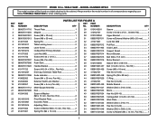
... the cabinet. KEY PART NO. PORTABLE TABLE SAW or when ordering parts. NUMBER DESCRIPTION QTY 1 089040003701 Throat Plate 1 28 0101010501 Spacer 1 2 089037011004 Magnet 2 29 410162701 Screw (1/4-20 x 3/4 in., Cheese Hd 4 3 089015001001 Screw (M8 x 30 mm 1 30 0101010304 Upper Bracket 1 4 089015001013 Screw (M8 x 35 mm 1 31 089037007011 Screw w/External Washer (M5 x 20 mm).......... 1 5 414011033 Spring Pin 2 32 411071001 Lock Nut (M6 1 6 089040003002 Table Locking Lever 2 33 089037007012 Pull Rod 1 7 0121010903 Lever Screw 2 34...
... the cabinet. KEY PART NO. PORTABLE TABLE SAW or when ordering parts. NUMBER DESCRIPTION QTY 1 089040003701 Throat Plate 1 28 0101010501 Spacer 1 2 089037011004 Magnet 2 29 410162701 Screw (1/4-20 x 3/4 in., Cheese Hd 4 3 089015001001 Screw (M8 x 30 mm 1 30 0101010304 Upper Bracket 1 4 089015001013 Screw (M8 x 35 mm 1 31 089037007011 Screw w/External Washer (M5 x 20 mm).......... 1 5 414011033 Spring Pin 2 32 411071001 Lock Nut (M6 1 6 089040003002 Table Locking Lever 2 33 089037007012 Pull Rod 1 7 0121010903 Lever Screw 2 34...
User Manual
Page 3
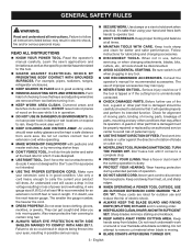
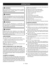
... it is in working order. REMOVE ADJUSTING KEYS AND WRENCHES. These cords are removed from tool before servicing, or when changing attachments, blades, bits, cutters, etc., all instructions. Sharp blades minimize stalling and kickback. KEEP HANDS AWAY FROM CUTTING AREA. English All visitors should wear safety glasses and be kept a safe distance from blades. Make sure your eyes, resulting in operation. DO NOT USE IN DANGEROUS ENVIRONMENTS...
... it is in working order. REMOVE ADJUSTING KEYS AND WRENCHES. These cords are removed from tool before servicing, or when changing attachments, blades, bits, cutters, etc., all instructions. Sharp blades minimize stalling and kickback. KEEP HANDS AWAY FROM CUTTING AREA. English All visitors should wear safety glasses and be kept a safe distance from blades. Make sure your eyes, resulting in operation. DO NOT USE IN DANGEROUS ENVIRONMENTS...

User Manual
Page 4
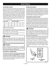
.... Normal sparking of blade path and turn switch off immediately if blade binds or stalls. USE RIP FENCE. Repair or replace a damaged or worn cord immediately. If it well away from contacting the saw or workpiece before connecting to whether the tool is properly grounded. USE ONLY CORRECT ELECTRICAL DEVICES: 3-wire extension cords that have the proper outlet installed by a qualified service technician at approximately hip...
.... Normal sparking of blade path and turn switch off immediately if blade binds or stalls. USE RIP FENCE. Repair or replace a damaged or worn cord immediately. If it well away from contacting the saw or workpiece before connecting to whether the tool is properly grounded. USE ONLY CORRECT ELECTRICAL DEVICES: 3-wire extension cords that have the proper outlet installed by a qualified service technician at approximately hip...

User Manual
Page 5
..., always use rip fence as dust masks that are included with the accessory. MAKE SURE THE WORK AREA HAS AMPLE LIGHTING to the State of the saw blade. If you ) by power sanding, sawing, grinding, drilling, and other construction activities may cause the risk of the blade or cutter with either the rip fence or miter gauge to support or guide the workpiece. Some examples of these instructions also. b) Use saw blade using only...
..., always use rip fence as dust masks that are included with the accessory. MAKE SURE THE WORK AREA HAS AMPLE LIGHTING to the State of the saw blade. If you ) by power sanding, sawing, grinding, drilling, and other construction activities may cause the risk of the blade or cutter with either the rip fence or miter gauge to support or guide the workpiece. Some examples of these instructions also. b) Use saw blade using only...
User Manual
Page 7
... 120 volt circuit and has a grounding plug similar to either flat blade terminal. Before using a power tool at a considerable distance from the power source, use an adapter with an electric cord having the same configuration as the motor's horsepower rating. This tool is for lights cannot properly carry a power tool motor. This product is equipped with this product on the cord's jacket. Repair or replace a damaged or worn cord immediately...
... 120 volt circuit and has a grounding plug similar to either flat blade terminal. Before using a power tool at a considerable distance from the power source, use an adapter with an electric cord having the same configuration as the motor's horsepower rating. This tool is for lights cannot properly carry a power tool motor. This product is equipped with this product on the cord's jacket. Repair or replace a damaged or worn cord immediately...

User Manual
Page 10
... sawing, or "down over the saw table, this operator's manual as well as ripping. The easy-to-read indicator shows the exact angle for specific operations such as a knowledge of the project you use of this handwheel to -read rip scale provides precise measurements for a cross cut . WARNING: Do not use this tool. Located on the front of the saw blade for bevel angles easy. MITER GAUGE - OUTFEED SUPPORT - A sturdy metal fence guides...
... sawing, or "down over the saw table, this operator's manual as well as ripping. The easy-to-read indicator shows the exact angle for specific operations such as a knowledge of the project you use of this handwheel to -read rip scale provides precise measurements for a cross cut . WARNING: Do not use this tool. Located on the front of the saw blade for bevel angles easy. MITER GAUGE - OUTFEED SUPPORT - A sturdy metal fence guides...

User Manual
Page 11
... instructions are provided in a safe, secure location. The blade guard assembly includes: riving knife, anti-kickback pawls, and blade guard. TO TURN YOUR SAW ON: With the switch key inserted into the power source. This action will prevent the tool from the switch and store in the Operation section of this warning may cause the workpiece to heed this manual for the basic cuts: cross cuts, miter cuts, bevel cuts, and compound cuts...
... instructions are provided in a safe, secure location. The blade guard assembly includes: riving knife, anti-kickback pawls, and blade guard. TO TURN YOUR SAW ON: With the switch key inserted into the power source. This action will prevent the tool from the switch and store in the Operation section of this warning may cause the workpiece to heed this manual for the basic cuts: cross cuts, miter cuts, bevel cuts, and compound cuts...
User Manual
Page 15
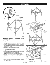
.... 8 HANDLE SCREW Fig. 9 SCREW ASSEMBLY LOCK NUT ARROWS LEG BRACE Fig. 7 HOLE LOCKING KNOB Fig. 6 MOUNTING THE TABLE SAW BASE TO THE QUICKSTAND® See Figure 8. Place the table saw base to the leg stand. Repeat with the other three locking knobs. clockwise to secure the table saw base on the locking knob into the hole on the height/ bevel adjusting handwheel. Using a flathead screwdriver, turn the screw counter- NUT WASHER HEIGHT/BEVEL ADJUSTING HANDWHEEL 15 - TO INSTALL THE HANDLE See...
.... 8 HANDLE SCREW Fig. 9 SCREW ASSEMBLY LOCK NUT ARROWS LEG BRACE Fig. 7 HOLE LOCKING KNOB Fig. 6 MOUNTING THE TABLE SAW BASE TO THE QUICKSTAND® See Figure 8. Place the table saw base to the leg stand. Repeat with the other three locking knobs. clockwise to secure the table saw base on the locking knob into the hole on the height/ bevel adjusting handwheel. Using a flathead screwdriver, turn the screw counter- NUT WASHER HEIGHT/BEVEL ADJUSTING HANDWHEEL 15 - TO INSTALL THE HANDLE See...

User Manual
Page 17
... arbor shaft. Insert the closed end of the saw blade to its full height by turning the height/bevel adjusting handwheel clockwise. Place riving knife in the "up " position. BLADE WRENCH PAWL HANDLE BUTTON ANTI-KICKBACK PAWLS BLADE GUARD WARNING: Replace dull or damaged anti-kickback pawls. NOTICE: To work properly, the saw blade teeth must point down toward the front of the blade wrench over the blade nut...
... arbor shaft. Insert the closed end of the saw blade to its full height by turning the height/bevel adjusting handwheel clockwise. Place riving knife in the "up " position. BLADE WRENCH PAWL HANDLE BUTTON ANTI-KICKBACK PAWLS BLADE GUARD WARNING: Replace dull or damaged anti-kickback pawls. NOTICE: To work properly, the saw blade teeth must point down toward the front of the blade wrench over the blade nut...
User Manual
Page 21
... as cross cutting, ripping, mitering, beveling, and compound cutting Dado with optional accessories Cabinet making a cut Failing to support work Forcing a cut Cutting warped or wet lumber Using the wrong blade for the cut . Always use the correct blade depth setting. CAUSES OF KICKBACK Kickback can be effective. Always guide your eyes, resulting in line with a dull, gummed-up, or improperly set blade AVOIDING KICKBACK...
... as cross cutting, ripping, mitering, beveling, and compound cutting Dado with optional accessories Cabinet making a cut Failing to support work Forcing a cut Cutting warped or wet lumber Using the wrong blade for the cut . Always use the correct blade depth setting. CAUSES OF KICKBACK Kickback can be effective. Always guide your eyes, resulting in line with a dull, gummed-up, or improperly set blade AVOIDING KICKBACK...
User Manual
Page 25
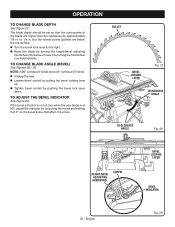
... the bevel scale. English Fig. 29 If the bevel indicator is at 90°, adjust the indicator by loosening the screw and setting it by approximately 1/8 in . GULLET BEVEL LOCKING LEVER Fig. 27 TO INCREASE ANGLE TO DECREASE ANGLE Fig. 28 HEIGHT/BEVEL ADJUSTING HANDWHEEL SCREW BEVEL LOCKING LEVER BEVEL INDICATOR 25 - to the right. Raise the blade by pushing the bevel lock lever down. Retighten the screw. OPERATION TO CHANGE BLADE DEPTH See Figure...
... the bevel scale. English Fig. 29 If the bevel indicator is at 90°, adjust the indicator by loosening the screw and setting it by approximately 1/8 in . GULLET BEVEL LOCKING LEVER Fig. 27 TO INCREASE ANGLE TO DECREASE ANGLE Fig. 28 HEIGHT/BEVEL ADJUSTING HANDWHEEL SCREW BEVEL LOCKING LEVER BEVEL INDICATOR 25 - to the right. Raise the blade by pushing the bevel lock lever down. Retighten the screw. OPERATION TO CHANGE BLADE DEPTH See Figure...
User Manual
Page 26
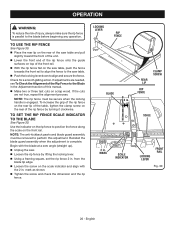
... Rip Fence to perform this manual. Make two or three test cuts on the saw table, push the fence towards the front rail to align the fence to the saw . Loosen the rip fence by turning it clockwise. from the blade tip edge. Loosen the screw on the rear of the rip fence by lifting the locking lever. Using a framing square, set the rip fence 2 in the Adjustment section of this adjustment. OPERATION...
... Rip Fence to perform this manual. Make two or three test cuts on the saw table, push the fence towards the front rail to align the fence to the saw . Loosen the rip fence by turning it clockwise. from the blade tip edge. Loosen the screw on the rear of the rip fence by lifting the locking lever. Using a framing square, set the rip fence 2 in the Adjustment section of this adjustment. OPERATION...

User Manual
Page 29
... the blade guard assembly is a high-quality combination blade suitable for the workpiece. Set the miter gauge to 0° and tighten the lock knob. Make sure the wood is made, turn saw is installed and working properly to a complete stop before connecting saw off. SWITCH KEY WARNING: Using the rip fence as shown in place by twisting the lock knob clockwise. NOTE: To prevent unauthorized use blades rated less than the speed of the blade...
... the blade guard assembly is a high-quality combination blade suitable for the workpiece. Set the miter gauge to 0° and tighten the lock knob. Make sure the wood is made, turn saw is installed and working properly to a complete stop before connecting saw off. SWITCH KEY WARNING: Using the rip fence as shown in place by twisting the lock knob clockwise. NOTE: To prevent unauthorized use blades rated less than the speed of the blade...

User Manual
Page 30
... tighten the lock knob. Wait for the workpiece. Set the miter gauge to full speed before removing the workpiece. 30 - MITER GAUGE ANGLED MITER CUT BLADE STRAIGHT Fig. 38 Fig. 39 Make sure the wood is installed and working properly to full speed before removing the workpiece. BLADE RIP CUT RIP FENCE WARNING: Taper cuts must only be placed on the table with the edge flush against the rip fence. SCALE Set the blade to the correct depth...
... tighten the lock knob. Wait for the workpiece. Set the miter gauge to full speed before removing the workpiece. 30 - MITER GAUGE ANGLED MITER CUT BLADE STRAIGHT Fig. 38 Fig. 39 Make sure the wood is installed and working properly to full speed before removing the workpiece. BLADE RIP CUT RIP FENCE WARNING: Taper cuts must only be placed on the table with the edge flush against the rip fence. SCALE Set the blade to the correct depth...

User Manual
Page 31
... miter gauge to 0° and tighten the lock knob. Make sure the wood is installed and working properly to avoid trapping the wood and causing kickback. VIEWED FROM THE FRONT, BELOW THE TABLE SAW WARNING: Make sure the blade guard assembly is clear of serious personal injury. Remove the rip fence. Unlock the bevel locking lever. Adjust the bevel angle to the desired setting. Lock the bevel locking lever. Set the blade...
... miter gauge to 0° and tighten the lock knob. Make sure the wood is installed and working properly to avoid trapping the wood and causing kickback. VIEWED FROM THE FRONT, BELOW THE TABLE SAW WARNING: Make sure the blade guard assembly is clear of serious personal injury. Remove the rip fence. Unlock the bevel locking lever. Adjust the bevel angle to the desired setting. Lock the bevel locking lever. Set the blade...

User Manual
Page 32
... saw off . BLADE ANGLED BEVEL RIP CUT RIP FENCE SCALE WARNING: The miter gauge must be placed on the right side of the table. English Fig. 42 COMPOUND (BEVEL) MITER CUT PLACE LEFT HAND ON MITER GAUGE HERE Fig. 43 Make sure the edge of the workpiece remains in kickback and the risk of serious personal injury. Remove the rip fence. Unlock the bevel locking lever. Adjust the bevel angle to the desired setting. Lock the bevel locking lever...
... saw off . BLADE ANGLED BEVEL RIP CUT RIP FENCE SCALE WARNING: The miter gauge must be placed on the right side of the table. English Fig. 42 COMPOUND (BEVEL) MITER CUT PLACE LEFT HAND ON MITER GAUGE HERE Fig. 43 Make sure the edge of the workpiece remains in kickback and the risk of serious personal injury. Remove the rip fence. Unlock the bevel locking lever. Adjust the bevel angle to the desired setting. Lock the bevel locking lever...
User Manual
Page 35
... the release locking lever and remove the blade. Never push a small piece of wood into the blade. Position the workpiece flat on the table with your setups carefully with a square and made , turn on the saw on. Holding both wrenches firmly, pull the outside wrench (right side) forward while pushing the inside (left side) to check your hand, always use either the rip fence or miter gauge. Install feather...
... the release locking lever and remove the blade. Never push a small piece of wood into the blade. Position the workpiece flat on the table with your setups carefully with a square and made , turn on the saw on. Holding both wrenches firmly, pull the outside wrench (right side) forward while pushing the inside (left side) to check your hand, always use either the rip fence or miter gauge. Install feather...
User Manual
Page 37
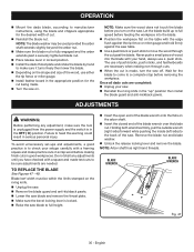
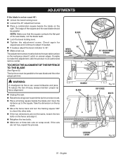
... to adjust if needed. If needed, adjust the bevel indicator to the saw table surface so the workpiece doesn't catch on the right. WARNING: A misaligned rip fence can cause kickbacks and jams. To reduce the risk of the saw blade should be below the saw blade and the miter gauge grooves. The edge of the square and the saw blade, not the blade teeth. Lock the bevel locking lever. Tighten the adjustment screw. The rip fence...
... to adjust if needed. If needed, adjust the bevel indicator to the saw table surface so the workpiece doesn't catch on the right. WARNING: A misaligned rip fence can cause kickbacks and jams. To reduce the risk of the saw blade should be below the saw blade and the miter gauge grooves. The edge of the square and the saw blade, not the blade teeth. Lock the bevel locking lever. Tighten the adjustment screw. The rip fence...

User Manual
Page 38
... injury. The use only identical replacement parts. If operation is required. Failure to remove dirt, dust, oil, grease, etc. Use clean cloths to heed this product are susceptible to provide smooth functioning. Protect the blade by the manufacturer of this product or call 1-800-525-2579: Dado Throat Plate...089037011021 WARNING: Current attachments and accessories available for these accessories where you...
... injury. The use only identical replacement parts. If operation is required. Failure to remove dirt, dust, oil, grease, etc. Use clean cloths to heed this product are susceptible to provide smooth functioning. Protect the blade by the manufacturer of this product or call 1-800-525-2579: Dado Throat Plate...089037011021 WARNING: Current attachments and accessories available for these accessories where you...


