

User Manual 4
Page 4
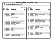
... (Rev:05) Mounting Bracket 1 Riving Knife 1 Clamping Bracket 1 Spring 1 Lever Assembly 1 Blade Guard Assembly (Inc. TABLE SAW - Key Nos. 95-100 1 Anti-Kickback Pawls Assembly 1...Saw Table 1 Outfeed Support Bracket 2 Rip Fence Assembly (See Figure C 1 Front Blade Guard Warning Label (Left 1 Front Blade Guard Warning Label (Right)......... 1 No Hands Warning Label 2 Guard Warning Label (...4 Screw (M4 x 10 mm, Pan Hd 3 Screw (M4 x 10 mm, Hex Hd 1 Arbor Nut 1 Outer Blade Washer 1 Saw Blade 1 Screw (M4 x 0.7 mm 3 Lock Nut (M6 3 Screw (M6 x 15 mm 1 Lever 1 Screw (M5 ...
... (Rev:05) Mounting Bracket 1 Riving Knife 1 Clamping Bracket 1 Spring 1 Lever Assembly 1 Blade Guard Assembly (Inc. TABLE SAW - Key Nos. 95-100 1 Anti-Kickback Pawls Assembly 1...Saw Table 1 Outfeed Support Bracket 2 Rip Fence Assembly (See Figure C 1 Front Blade Guard Warning Label (Left 1 Front Blade Guard Warning Label (Right)......... 1 No Hands Warning Label 2 Guard Warning Label (...4 Screw (M4 x 10 mm, Pan Hd 3 Screw (M4 x 10 mm, Hex Hd 1 Arbor Nut 1 Outer Blade Washer 1 Saw Blade 1 Screw (M4 x 0.7 mm 3 Lock Nut (M6 3 Screw (M6 x 15 mm 1 Lever 1 Screw (M5 ...

User Manual 4
Page 6
...0101140904 16 089037011051 17 0134010221 18 089037011024 19 089037011023 20 089037011902 21 410601004 22 984406003 Carriage Bolt (5/16-18 x 1-1/2 in 1 Knob Ring 1 Blade Wrench 1 Blade Wrench 1 Wing Nut 1 Cabinet Assembly (Inc Key Nos. 8-9, 20, and 35 1 Screw (M4 x 7 mm, Flat Hd 6 ...x D13 x 1.5t 1 Handwheel Lever 1 Handwheel Knob Screw 1 6 MODEL NUMBER RTS21 The model number will be found on a label attached to the cabinet. RYOBI 10 in. PORTABLE TABLE SAW or when ordering parts. x D16 x 1t 1 Spring 1 Knob 1 Handwheel 1 Elevating Shaft 1 E-Ring 1 Front Panel Warning ...
...0101140904 16 089037011051 17 0134010221 18 089037011024 19 089037011023 20 089037011902 21 410601004 22 984406003 Carriage Bolt (5/16-18 x 1-1/2 in 1 Knob Ring 1 Blade Wrench 1 Blade Wrench 1 Wing Nut 1 Cabinet Assembly (Inc Key Nos. 8-9, 20, and 35 1 Screw (M4 x 7 mm, Flat Hd 6 ...x D13 x 1.5t 1 Handwheel Lever 1 Handwheel Knob Screw 1 6 MODEL NUMBER RTS21 The model number will be found on a label attached to the cabinet. RYOBI 10 in. PORTABLE TABLE SAW or when ordering parts. x D16 x 1t 1 Spring 1 Knob 1 Handwheel 1 Elevating Shaft 1 E-Ring 1 Front Panel Warning ...

User Manual 5
Page 4
... Warning Label (Left 1 Front Blade Guard Warning Label (Right)......... 1 No Hands Warning Label 2 Guard Warning Label (Left 1 Guard Warning Label (Right 1 Warning Label (Upper Barrier 1 Dado Throat Plate (Optional 1 Operator's Manual (089037011908) 4 RYOBI 10 in . NUMBER DESCRIPTION QTY 81 089037007022...Indicator 1 Indicator Bracket 1 Toothed Hex Nut (M6 4 Screw (M4 x 10 mm, Pan Hd 3 Screw (M4 x 10 mm, Hex Hd 1 Arbor Nut 1 Outer Blade Washer 1 Saw Blade 1 Screw (M4 x 0.7 mm 3 Lock Nut (M6 3 Screw (M6 x 15 mm 1 Lever 1 Screw (M5 x 25 mm 4 Clamp Lock 1 Clamp 1 Plate...
... Warning Label (Left 1 Front Blade Guard Warning Label (Right)......... 1 No Hands Warning Label 2 Guard Warning Label (Left 1 Guard Warning Label (Right 1 Warning Label (Upper Barrier 1 Dado Throat Plate (Optional 1 Operator's Manual (089037011908) 4 RYOBI 10 in . NUMBER DESCRIPTION QTY 81 089037007022...Indicator 1 Indicator Bracket 1 Toothed Hex Nut (M6 4 Screw (M4 x 10 mm, Pan Hd 3 Screw (M4 x 10 mm, Hex Hd 1 Arbor Nut 1 Outer Blade Washer 1 Saw Blade 1 Screw (M4 x 0.7 mm 3 Lock Nut (M6 3 Screw (M6 x 15 mm 1 Lever 1 Screw (M5 x 25 mm 4 Clamp Lock 1 Clamp 1 Plate...
User Manual 5
Page 6
RYOBI 10 in . x D16 x 1t 1 Spring 1 Knob 1 Handwheel 1 Elevating Shaft 1 E-Ring 1 Front Panel Warning Label 1 Screw (M14 x 18 mm, Pan Hd 4 KEY NO. 22 23 24 ... 13 089040003007 14 089110101033 15 0101140904 16 089040003011 17 0134010221 18 089037011024 19 089037011023 20 089040003902 21 410601004 Carriage Bolt (5/16-18 x 1-1/2 in 1 Knob Ring 1 Blade Wrench 1 Blade Wrench 1 Wing Nut 1 Cabinet Assembly (Inc Key Nos. 9, 20, and 35 1 Screw (M4 x 7 mm, Flat Hd 6 Handwheel Knob Screw 1 Front Panel Label 1 Plastic Washer...
RYOBI 10 in . x D16 x 1t 1 Spring 1 Knob 1 Handwheel 1 Elevating Shaft 1 E-Ring 1 Front Panel Warning Label 1 Screw (M14 x 18 mm, Pan Hd 4 KEY NO. 22 23 24 ... 13 089040003007 14 089110101033 15 0101140904 16 089040003011 17 0134010221 18 089037011024 19 089037011023 20 089040003902 21 410601004 Carriage Bolt (5/16-18 x 1-1/2 in 1 Knob Ring 1 Blade Wrench 1 Blade Wrench 1 Wing Nut 1 Cabinet Assembly (Inc Key Nos. 9, 20, and 35 1 Screw (M4 x 7 mm, Flat Hd 6 Handwheel Knob Screw 1 Front Panel Label 1 Plastic Washer...
User Manual
Page 3
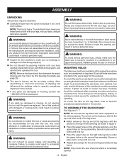
.... DO NOT leave tools or pieces of improper accessories may affect its intended function. Keep the work or around or over the blade while blade is in good condition. Don't force the tool or attachment to hold work area. The smaller the gauge number, the heavier ...) IN PLACE and in working order. REMOVE ADJUSTING KEYS AND WRENCHES. Keep cord away from tool before servicing, or when changing attachments, blades, bits, cutters, etc., all times. MAINTAIN TOOLS WITH CARE. Read the operator's manual carefully. Consult the operator's manual for alignment ...
.... DO NOT leave tools or pieces of improper accessories may affect its intended function. Keep the work or around or over the blade while blade is in good condition. Don't force the tool or attachment to hold work area. The smaller the gauge number, the heavier ...) IN PLACE and in working order. REMOVE ADJUSTING KEYS AND WRENCHES. Keep cord away from tool before servicing, or when changing attachments, blades, bits, cutters, etc., all times. MAINTAIN TOOLS WITH CARE. Read the operator's manual carefully. Consult the operator's manual for alignment ...

User Manual
Page 4
... receptacle. CHECK WITH A QUALIFIED ELECTRICIAN or service personnel if the grounding instructions are not listed may cause the risk of blade pinching and kickback, always support large panels. REMOVE ALL FENCES AND AUXILIARY TABLES before connecting to Make A Jig (For Rip...STOCK. If tool is tight and not making contact with the accessory. DOUBLE CHECK ALL SETUPS. Kickback occurs when the blade stalls rapidly and workpiece is properly grounded. USE ONLY CORRECT ELECTRICAL DEVICES: 3-wire extension cords that have the proper outlet...
... receptacle. CHECK WITH A QUALIFIED ELECTRICIAN or service personnel if the grounding instructions are not listed may cause the risk of blade pinching and kickback, always support large panels. REMOVE ALL FENCES AND AUXILIARY TABLES before connecting to Make A Jig (For Rip...STOCK. If tool is tight and not making contact with the accessory. DOUBLE CHECK ALL SETUPS. Kickback occurs when the blade stalls rapidly and workpiece is properly grounded. USE ONLY CORRECT ELECTRICAL DEVICES: 3-wire extension cords that have the proper outlet...

User Manual
Page 5
... of your body in this type of work before disconnecting it, to avoid accidental starting when reconnecting to power supply. ONLY USE BLADES within the thickness range stamped on the riving knife. THIS TOOL should have the following markings: a) Wear eye protection. e) Not...instructions also. Instructions for safe use of accessories are included with safe operation BEFORE performing any work thrown back toward you) by: a) Keeping blade sharp. SPECIFIC SAFETY RULES WHEN MAKING NON-THROUGH RIP CUTS, always use a push stick, push block, and/or featherboard so your...
... of your body in this type of work before disconnecting it, to avoid accidental starting when reconnecting to power supply. ONLY USE BLADES within the thickness range stamped on the riving knife. THIS TOOL should have the following markings: a) Wear eye protection. e) Not...instructions also. Instructions for safe use of accessories are included with safe operation BEFORE performing any work thrown back toward you) by: a) Keeping blade sharp. SPECIFIC SAFETY RULES WHEN MAKING NON-THROUGH RIP CUTS, always use a push stick, push block, and/or featherboard so your...

User Manual
Page 6
.... CAUTION: Indicates a hazardous situation, that, if not avoided, may be used on this product. No Hands Symbol Failure to keep your hands away from the blade will allow you to operate the tool better and safer. SYMBOL NAME DESIGNATION/EXPLANATION Safety Alert Indicates a potential personal injury hazard. messages relating to a potential...
.... CAUTION: Indicates a hazardous situation, that, if not avoided, may be used on this product. No Hands Symbol Failure to keep your hands away from the blade will allow you to operate the tool better and safer. SYMBOL NAME DESIGNATION/EXPLANATION Safety Alert Indicates a potential personal injury hazard. messages relating to a potential...
User Manual
Page 7
... in figure 1. WARNING: Check extension cords before each use . SPEED AND WIRING The no-load speed of power and causing the motor to either flat blade terminal. This speed is equipped with this product on the cord's jacket. Wire that can result in an extension cord. A line that is required, do...
... in figure 1. WARNING: Check extension cords before each use . SPEED AND WIRING The no-load speed of power and causing the motor to either flat blade terminal. This speed is equipped with this product on the cord's jacket. Wire that can result in an extension cord. A line that is required, do...
User Manual
Page 8
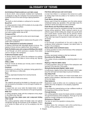
... one minute. Push Blocks and Push Sticks (table saws) Devices used to feed the workpiece over , under, behind, or in the direction of the blade to the table surface. Taper Cut A cut where the material being cut will be used for insertion of the cut made across the grain or... the direction of cut has a different width at 90°. Cross Cut A cutting or shaping operation made with the blade at any ripping operation. Kerf The material removed by the blade in a through cut without the workpiece being done. When making a narrow rip cut positioned on the end or edge ...
... one minute. Push Blocks and Push Sticks (table saws) Devices used to feed the workpiece over , under, behind, or in the direction of the blade to the table surface. Taper Cut A cut where the material being cut will be used for insertion of the cut made across the grain or... the direction of cut has a different width at 90°. Cross Cut A cutting or shaping operation made with the blade at any ripping operation. Kerf The material removed by the blade in a through cut without the workpiece being done. When making a narrow rip cut positioned on the end or edge ...

User Manual
Page 9
English ANTI-KICKBACK PAWLS MITER GAUGE RIVING KNIFE BLADE GUARD RIP FENCE SLIDING TABLE EXTENSION OUTFEED SUPPORT FRONT RAIL BLADE WRENCH STORAGE LOCKING LEVER RIP SCALE TABLE LOCKING LEVER STORAGE BRACKET(S) HEIGHT/BEVEL ADJUSTING HANDWHEEL SWITCH BEVEL LOCKING LEVER BEVEL SCALE BEVEL INDICATOR Fig. 2 9 - FEATURES PRODUCT SPECIFICATIONS Blade Arbor 5/8 in . Blade Tilt 0˚ - 45˚ Rating 120 V, AC only, 60 Hz Input 15 Amps No Load Speed 5,000 r/min. (RPM) Cutting Depth at 45 2-1/2 in . Blade Diameter 10 in . Cutting Depth at 0 3 in .
English ANTI-KICKBACK PAWLS MITER GAUGE RIVING KNIFE BLADE GUARD RIP FENCE SLIDING TABLE EXTENSION OUTFEED SUPPORT FRONT RAIL BLADE WRENCH STORAGE LOCKING LEVER RIP SCALE TABLE LOCKING LEVER STORAGE BRACKET(S) HEIGHT/BEVEL ADJUSTING HANDWHEEL SWITCH BEVEL LOCKING LEVER BEVEL SCALE BEVEL INDICATOR Fig. 2 9 - FEATURES PRODUCT SPECIFICATIONS Blade Arbor 5/8 in . Blade Tilt 0˚ - 45˚ Rating 120 V, AC only, 60 Hz Input 15 Amps No Load Speed 5,000 r/min. (RPM) Cutting Depth at 45 2-1/2 in . Blade Diameter 10 in . Cutting Depth at 0 3 in .

User Manual
Page 10
...- If the workpiece should be within the limits stamped on the removable anti-kickback pawls point away from the switch. carbide tipped combination blade provided with complete information. Bevel angles are attempting. This lever, placed just under the saw table. MITER GAUGE - MITER GAUGE GROOVES ...-read indicator shows the exact angle for a miter cut . Your local dealer can provide you use blades rated less than the saw blade for height adjustments or blade replacement. Blade kerf width must be pulled back toward the operator. WARNING: Do not use the 10 in the grooves...
...- If the workpiece should be within the limits stamped on the removable anti-kickback pawls point away from the switch. carbide tipped combination blade provided with complete information. Bevel angles are attempting. This lever, placed just under the saw table. MITER GAUGE - MITER GAUGE GROOVES ...-read indicator shows the exact angle for a miter cut . Your local dealer can provide you use blades rated less than the saw blade for height adjustments or blade replacement. Blade kerf width must be pulled back toward the operator. WARNING: Do not use the 10 in the grooves...

User Manual
Page 11
...prevent unauthorized and possible hazardous use by an insert called the throat plate. SWITCH ASSEMBLY See Figure 3. This feature is not in use the blade guard assembly for lengthwise cuts. WARNING: ALWAYS remove the switch key when the tool is intended to heed this manual for the basic cuts: cross...workpiece is not in the OFF ( O ) position before operating the switch to position work for all through the table and is set with the blade before plugging tool into the switch, lift the switch to use and keep it in locking feature. The rip fence is equipped with a switch ...
...prevent unauthorized and possible hazardous use by an insert called the throat plate. SWITCH ASSEMBLY See Figure 3. This feature is not in use the blade guard assembly for lengthwise cuts. WARNING: ALWAYS remove the switch key when the tool is intended to heed this manual for the basic cuts: cross...workpiece is not in the OFF ( O ) position before operating the switch to position work for all through the table and is set with the blade before plugging tool into the switch, lift the switch to use and keep it in locking feature. The rip fence is equipped with a switch ...

User Manual
Page 13
Blade Wrench 2 E. Indicator 1 I Q O J G A. Switch Key 1 O. Screw 8 Q. Sliding Table Assembly 1 L. End Cap 1 M. Blade Guard 1 C. Rip Fence 1 G. Stand Legs 2 K. Anti-Kickback Pawls 1 B. Push Stick 1 H. Lock Nut 8 13 - English Screw 2 Fig. 5 J. Leg Brace 2 P. Hex Key 1 N. Handle Assembly 1 F. Miter Gauge 1 D. LOOSE PARTS The following items are included with your table saw: A C N B I K H D M F P E L I .
Blade Wrench 2 E. Indicator 1 I Q O J G A. Switch Key 1 O. Screw 8 Q. Sliding Table Assembly 1 L. End Cap 1 M. Blade Guard 1 C. Rip Fence 1 G. Stand Legs 2 K. Anti-Kickback Pawls 1 B. Push Stick 1 H. Lock Nut 8 13 - English Screw 2 Fig. 5 J. Leg Brace 2 P. Hex Key 1 N. Handle Assembly 1 F. Miter Gauge 1 D. LOOSE PARTS The following items are included with your table saw: A C N B I K H D M F P E L I .
User Manual
Page 14
...in figure 6. Place the upper holes on the Loose Parts List are damaged or missing, do not operate this leg stand with the blade or allow hands to comply could result in accidental starting and possible serious personal injury. Hold it . Failure to heed this warning can result in... this manual. If any parts on the left side leg brace over or across the blade. NEVER operate the saw is complete. Carefully check the workbench after mounting to make sure the table saw is securely mounted to specific procedures explained...
...in figure 6. Place the upper holes on the Loose Parts List are damaged or missing, do not operate this leg stand with the blade or allow hands to comply could result in accidental starting and possible serious personal injury. Hold it . Failure to heed this warning can result in... this manual. If any parts on the left side leg brace over or across the blade. NEVER operate the saw is complete. Carefully check the workbench after mounting to make sure the table saw is securely mounted to specific procedures explained...
User Manual
Page 16
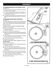
...the throat plate. To place in riving knife "down" position for all nonthrough cutting: Remove the throat plate. Raise the saw blade by turning the height/bevel adjusting handwheel clockwise. Unlock the release lever by pulling it up. Grasp the riving knife and pull...for all other cutting operations. Unplug the saw. ASSEMBLY TO REMOVE/REPLACE THE THROAT PLATE See Figure 10. Lower the blade by turning the height/bevel adjusting handwheel counterclockwise. To remove the throat plate, place your index finger in the hole and lift the...
...the throat plate. To place in riving knife "down" position for all nonthrough cutting: Remove the throat plate. Raise the saw blade by turning the height/bevel adjusting handwheel clockwise. Unlock the release lever by pulling it up. Grasp the riving knife and pull...for all other cutting operations. Unplug the saw. ASSEMBLY TO REMOVE/REPLACE THE THROAT PLATE See Figure 10. Lower the blade by turning the height/bevel adjusting handwheel counterclockwise. To remove the throat plate, place your index finger in the hole and lift the...

User Manual
Page 17
...end of serious personal injury. Installing the guarding components onto the riving knife in any other position will prevent them from the blade wrench storage area. Using blade wrenches, place the flat open end into the flats on the arbor shaft. Insert the closed end of the... blade wrench over the blade nut. English BLADE WRENCH BLADE NUT Fig. 12 Fig. 13 GUARD LEVER Fig. 14 To loosen the blade: Remove the blade wrench from working as designed, which could cause damage to heed this warning ...
...end of serious personal injury. Installing the guarding components onto the riving knife in any other position will prevent them from the blade wrench storage area. Using blade wrenches, place the flat open end into the flats on the arbor shaft. Insert the closed end of the... blade wrench over the blade nut. English BLADE WRENCH BLADE NUT Fig. 12 Fig. 13 GUARD LEVER Fig. 14 To loosen the blade: Remove the blade wrench from working as designed, which could cause damage to heed this warning ...

User Manual
Page 18
..."up " position. Reinstall the throat plate. Place a framing square or straight edge against both the blade and riving knife evenly with the saw blade, adjustment is square against blade from blade. ASSEMBLY Anti-kickback pawls should only be installed for through cuts. Unplug the saw. Raise...the table, the riving knife is not parallel to make sure pawls are aligned when the framing square contacts both the saw blade by turning the height/bevel adjusting handwheel clockwise. Place riving knife in the riving knife. Push the pawl handle ...
..."up " position. Reinstall the throat plate. Place a framing square or straight edge against both the blade and riving knife evenly with the saw blade, adjustment is square against blade from blade. ASSEMBLY Anti-kickback pawls should only be installed for through cuts. Unplug the saw. Raise...the table, the riving knife is not parallel to make sure pawls are aligned when the framing square contacts both the saw blade by turning the height/bevel adjusting handwheel clockwise. Place riving knife in the riving knife. Push the pawl handle ...

User Manual
Page 19
...TABLE LOCKING LEVER END CAP SCREW EXTENSION ROD 19 - ASSEMBLY To adjust (horizontally and vertically): Remove the anti-kickback pawls and blade guard assembly. From the back of the saw, loosen the screws holding the mounting bracket. Reposition the riving knife ...locking levers. Insert sliding table assembly into table locking levers. Push the table assembly until it rests against the saw blade. Once properly aligned, securely retighten all screws. Check again for squareness and continue to hold sliding table assembly into ...
...TABLE LOCKING LEVER END CAP SCREW EXTENSION ROD 19 - ASSEMBLY To adjust (horizontally and vertically): Remove the anti-kickback pawls and blade guard assembly. From the back of the saw, loosen the screws holding the mounting bracket. Reposition the riving knife ...locking levers. Insert sliding table assembly into table locking levers. Push the table assembly until it rests against the saw blade. Once properly aligned, securely retighten all screws. Check again for squareness and continue to hold sliding table assembly into ...

User Manual
Page 20
ASSEMBLY TO STORE THE TABLE SAW ACCESSORIES AND LEG STAND See Figures 19 - 20. When not in use, store the accessories securely by snapping each accessory in back of the saw cabinet) specifically designed for the saw cabinet using hook and look straps. The table saw has two convenient storage areas (one on either side of saw 's accessories. To store the leg stand, close the stand and secure in place. BLADE WRENCHES Fig. 19 20 - English PUSH STICK STORAGE HOOK RIP FENCE MITER GAUGE Fig. 20
ASSEMBLY TO STORE THE TABLE SAW ACCESSORIES AND LEG STAND See Figures 19 - 20. When not in use, store the accessories securely by snapping each accessory in back of the saw cabinet) specifically designed for the saw cabinet using hook and look straps. The table saw has two convenient storage areas (one on either side of saw 's accessories. To store the leg stand, close the stand and secure in place. BLADE WRENCHES Fig. 19 20 - English PUSH STICK STORAGE HOOK RIP FENCE MITER GAUGE Fig. 20


