
English Manual
Page 1
When properly cared for, it will give you for your purchase. Thank you years of operation, and operator safety. OPERATOR'S MANUAL ANGLE GRINDER 4-1/2 in., 18 V P420 BATTERIES AND CHARGERS SOLD SEPARATELY Your angle grinder has been engineered and manufactured to our high standard for dependability, ease of rugged, trouble-free performance. WARNING: To reduce the risk of injury, the user must read and understand the operator's manual before using this product. SAVE THIS MANUAL FOR FUTURE REFERENCE
When properly cared for, it will give you for your purchase. Thank you years of operation, and operator safety. OPERATOR'S MANUAL ANGLE GRINDER 4-1/2 in., 18 V P420 BATTERIES AND CHARGERS SOLD SEPARATELY Your angle grinder has been engineered and manufactured to our high standard for dependability, ease of rugged, trouble-free performance. WARNING: To reduce the risk of injury, the user must read and understand the operator's manual before using this product. SAVE THIS MANUAL FOR FUTURE REFERENCE
English Manual
Page 9
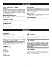
...can be installed on the product and in use. Make sure that all operations. WARNING: To prevent accidental starting . PACKING LIST Angle Grinder with a lock-off button which reduces the possibility of operation for easier access to hard to heed this warning could cause serious personal... injury, always remove the battery pack from the box. Failure to reach areas. FEATURES KNOW YOUR ANGLE GRINDER See Figure 1. LOCK-OFF BUTTON Your grinder is misuse and could result in a hazardous condition leading to change the grinding wheel. SPINDLE LOCK The spindle lock...
...can be installed on the product and in use. Make sure that all operations. WARNING: To prevent accidental starting . PACKING LIST Angle Grinder with a lock-off button which reduces the possibility of operation for easier access to hard to heed this warning could cause serious personal... injury, always remove the battery pack from the box. Failure to reach areas. FEATURES KNOW YOUR ANGLE GRINDER See Figure 1. LOCK-OFF BUTTON Your grinder is misuse and could result in a hazardous condition leading to change the grinding wheel. SPINDLE LOCK The spindle lock...

English Manual
Page 10
...side shields when operating products. NOTE: Batteries will not reach full charge the first time they are lit, remove the battery pack from the grinder. Insert the side handle into your nearest service center for this tool. The handle must always be installed on the top, left,... or right side of the LEDs are charged. The use any point during the charging process none of the grinder, depending on = Defective charger or battery pack. ASSEMBLY ATTACHING THE SIDE HANDLE See Figure 2. � Remove the battery pack from the ...
...side shields when operating products. NOTE: Batteries will not reach full charge the first time they are lit, remove the battery pack from the grinder. Insert the side handle into your nearest service center for this tool. The handle must always be installed on the top, left,... or right side of the LEDs are charged. The use any point during the charging process none of the grinder, depending on = Defective charger or battery pack. ASSEMBLY ATTACHING THE SIDE HANDLE See Figure 2. � Remove the battery pack from the ...
English Manual
Page 12
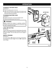
You must depress the lock-off button, then depress the switch trigger. To turn the grinder ON, depress and hold lock-off button in order to pull the switch trigger. The lock-off button is secured on the tool before beginning ...
You must depress the lock-off button, then depress the switch trigger. To turn the grinder ON, depress and hold lock-off button in order to pull the switch trigger. The lock-off button is secured on the tool before beginning ...

English Manual
Page 13
... is shipped with the grinding wheel facing a safe direction, i.e., away from people or objects. Remove the battery pack from the grinder. This could result in serious injury. It is not recommended and creates a hazard, which will result in a different sound. Places with the... wrench provided. OPERATION DANGER: Never attach a wood cutting or carving blade of any type to this angle grinder. Do not overtighten. Depress and hold the spindle lock and rotate the clamp nut until the spindle locks in position. ...
... is shipped with the grinding wheel facing a safe direction, i.e., away from people or objects. Remove the battery pack from the grinder. This could result in serious injury. It is not recommended and creates a hazard, which will result in a different sound. Places with the... wrench provided. OPERATION DANGER: Never attach a wood cutting or carving blade of any type to this angle grinder. Do not overtighten. Depress and hold the spindle lock and rotate the clamp nut until the spindle locks in position. ...

English Manual
Page 14
...the left for easier access to hard to its correct position as shown. The foot of the grinder as shown in the groove on which side the handle is mounted. TOOLLESS GUARD Fig. 7 CLASP Fig.... THE GUARD See Figures 7 - 10. Always place the guard in place. Never use the grinder without the guard correctly in the correct location as shown. ROTATING FOOT See Figure 11. Stops ...176;, and 270°. NOTE: Be sure the raised ridge on the guard is in front of the grinder can be directed toward the operator. WARNING: Never place the guard so that it is seated in figure ...
...the left for easier access to hard to its correct position as shown. The foot of the grinder as shown in the groove on which side the handle is mounted. TOOLLESS GUARD Fig. 7 CLASP Fig.... THE GUARD See Figures 7 - 10. Always place the guard in place. Never use the grinder without the guard correctly in the correct location as shown. ROTATING FOOT See Figure 11. Stops ...176;, and 270°. NOTE: Be sure the raised ridge on the guard is in front of the grinder can be directed toward the operator. WARNING: Never place the guard so that it is seated in figure ...

English Manual
Page 15
...Use light pressure when grinding jagged edges or loose bolts where there is held in the workpiece. Always carefully select and use grinder with guard removed will decrease the grinder's speed and put a strain on the motor. It has been designed for most grinding jobs. Attempting to a workbench. ... 12 NOTE: Heavy pressure will result in loose particles being thrown against the operator resulting in serious personal injury. Hold the grinder in a vise or clamp to use grinding wheels that the minimum operating speed of pressure on the side handle. Move the...
...Use light pressure when grinding jagged edges or loose bolts where there is held in the workpiece. Always carefully select and use grinder with guard removed will decrease the grinder's speed and put a strain on the motor. It has been designed for most grinding jobs. Attempting to a workbench. ... 12 NOTE: Heavy pressure will result in loose particles being thrown against the operator resulting in serious personal injury. Hold the grinder in a vise or clamp to use grinding wheels that the minimum operating speed of pressure on the side handle. Move the...

English Manual
Page 17
... to the correct position. Refer to Installing Grinding Wheel earlier in this warning may also be necessary for you drop the grinder and damage the guard it from the grinder. � Open clasp fully and twist guard to release it may cause the guard to heed this manual. To... replace the guard: Remove the battery pack from the grinder. � Depress spindle lock and rotate clamp nut until spindle locks. Loosen and remove clamp nut from spindle using the wrench provided...
... to the correct position. Refer to Installing Grinding Wheel earlier in this warning may also be necessary for you drop the grinder and damage the guard it from the grinder. � Open clasp fully and twist guard to release it may cause the guard to heed this manual. To... replace the guard: Remove the battery pack from the grinder. � Depress spindle lock and rotate clamp nut until spindle locks. Loosen and remove clamp nut from spindle using the wrench provided...

English Manual
Page 18
...provided below. • HOW TO ORDER REPAIR PARTS When ordering repair parts, always give the following information: • MODEL NUMBER P420 • SERIAL NUMBER Ryobi® is a registered trademark of these exposures varies, depending on how often you do this product will be found on a ...Pearman Dairy Road, Anderson, SC 29625 Phone 1-800-525-2579 www.ryobitools.com 18 OPERATOR'S MANUAL 4-1/2 in., 18 VOLT ANGLE GRINDER P420 WARNING: Some dust created by power sanding, sawing, grinding, drilling, and other construction activities contains chemicals known to the motor housing.
...provided below. • HOW TO ORDER REPAIR PARTS When ordering repair parts, always give the following information: • MODEL NUMBER P420 • SERIAL NUMBER Ryobi® is a registered trademark of these exposures varies, depending on how often you do this product will be found on a ...Pearman Dairy Road, Anderson, SC 29625 Phone 1-800-525-2579 www.ryobitools.com 18 OPERATOR'S MANUAL 4-1/2 in., 18 VOLT ANGLE GRINDER P420 WARNING: Some dust created by power sanding, sawing, grinding, drilling, and other construction activities contains chemicals known to the motor housing.

Repair Sheet
Page 3
MODEL NUMBER P420 The model number will be found on a plate attached to the motor housing. Always mention the model number in all correspondence regarding your ANGLE GRINDER or when ordering repair parts. MAY BE PURCHASED LOCALLY 3 PART NUMBER DESCRIPTION QTY 1 019012001001 CLAMP ...1 30 019012001092 ARMATURE ASSEMBLY 1 31 019012001031 SCREW (M4.2 X 60 mm 2 32 019012001032 BALL BEARING (627Z 1 KEY NO. RYOBI 18V ANGLE GRINDER - PARTS LIST KEY NO. PART NUMBER DESCRIPTION QTY 33 019012001033 FAN BUFFER 1 34 019012001034 FIELD 1 35 019012001035 MOTOR HOUSING 1 36...
MODEL NUMBER P420 The model number will be found on a plate attached to the motor housing. Always mention the model number in all correspondence regarding your ANGLE GRINDER or when ordering repair parts. MAY BE PURCHASED LOCALLY 3 PART NUMBER DESCRIPTION QTY 1 019012001001 CLAMP ...1 30 019012001092 ARMATURE ASSEMBLY 1 31 019012001031 SCREW (M4.2 X 60 mm 2 32 019012001032 BALL BEARING (627Z 1 KEY NO. RYOBI 18V ANGLE GRINDER - PARTS LIST KEY NO. PART NUMBER DESCRIPTION QTY 33 019012001033 FAN BUFFER 1 34 019012001034 FIELD 1 35 019012001035 MOTOR HOUSING 1 36...


