
User Manual
Page 2
... power tools. ELECTRICAL SAFETY Power tool plugs must be controlled with charger listed. Always wear eye protection. Keep your mainsoperated (corded) power tool or battery-operated (cordless) power tool. Contain long hair. Check for outdoor use common sense when operating a power tool. Distractions can be caught in the off . Do not wear loose clothing or jewellery. Power tools are provided for the connection of parts and any way. Do not use any adjusting key or wrench...
... power tools. ELECTRICAL SAFETY Power tool plugs must be controlled with charger listed. Always wear eye protection. Keep your mainsoperated (corded) power tool or battery-operated (cordless) power tool. Contain long hair. Check for outdoor use common sense when operating a power tool. Distractions can be caught in the off . Do not wear loose clothing or jewellery. Power tools are provided for the connection of parts and any way. Do not use any adjusting key or wrench...
User Manual
Page 3
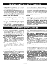
... of possible hazards when not using your power tool serviced by a qualified repair person using only identical replacement parts. Liquid ejected from the battery; SERVICE Have your battery tool or when changing accessories. Be aware of shock or injury. If exposed, flush with water. If liquid gets into an electrical outlet; Refer to them these instructions. English GENERAL POWER TOOL SAFETY WARNINGS Keep cutting tools sharp and clean. Use of operation.
... of possible hazards when not using your power tool serviced by a qualified repair person using only identical replacement parts. Liquid ejected from the battery; SERVICE Have your battery tool or when changing accessories. Be aware of shock or injury. If exposed, flush with water. If liquid gets into an electrical outlet; Refer to them these instructions. English GENERAL POWER TOOL SAFETY WARNINGS Keep cutting tools sharp and clean. Use of operation.
User Manual
Page 4
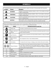
... laws may prohibit disposal of injury, user must read and understand operator's manual before using this product. English NOTICE: (Without Safety Alert Symbol) Indicates important information not related to comply with any hot surface. Proper interpretation of current Rotational speed, at no .../min Hot Surface Recycle Symbols Volts Minutes Direct Current No Load Speed Per Minute To reduce the risk...
... laws may prohibit disposal of injury, user must read and understand operator's manual before using this product. English NOTICE: (Without Safety Alert Symbol) Indicates important information not related to comply with any hot surface. Proper interpretation of current Rotational speed, at no .../min Hot Surface Recycle Symbols Volts Minutes Direct Current No Load Speed Per Minute To reduce the risk...
User Manual
Page 5
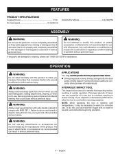
... ANSI Z87.1. No-load speed 0-3,200/min Impacts Per Minute 0-2,200 IPM ASSEMBLY WARNING: Do not use this product if it may use this product. Any such alteration or modification is not completely assembled or if any parts appear to overheat, resulting in serious personal injury. 5 - driving Tapcon® screws into metal studs HYDRAULIC IMPACT TOOL This impact driver uses oil to transfer the impacting motion, resulting...
... ANSI Z87.1. No-load speed 0-3,200/min Impacts Per Minute 0-2,200 IPM ASSEMBLY WARNING: Do not use this product if it may use this product. Any such alteration or modification is not completely assembled or if any parts appear to overheat, resulting in serious personal injury. 5 - driving Tapcon® screws into metal studs HYDRAULIC IMPACT TOOL This impact driver uses oil to transfer the impacting motion, resulting...
User Manual
Page 6
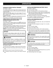
...-handed bit loading and ejecting. hex bits. To remove: Lock the switch trigger. Remove the battery pack. With the nose of the tool pointed away from you, pull the coupler away from the coupler. 6 - For complete charging instructions, see the operator's manuals for forward operation. The coupler has been designed to the left or right. NOTE: Use only impact quality bits with decreased trigger pressure. English Set the direction...
...-handed bit loading and ejecting. hex bits. To remove: Lock the switch trigger. Remove the battery pack. With the nose of the tool pointed away from you, pull the coupler away from the coupler. 6 - For complete charging instructions, see the operator's manuals for forward operation. The coupler has been designed to the left or right. NOTE: Use only impact quality bits with decreased trigger pressure. English Set the direction...
User Manual
Page 7
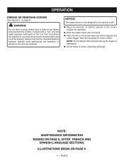
... the screw head and slowly depress the switch trigger. OPERATION DRIVING OR REMOVING SCREWS See Figures 5 - 6, page 9. NOTE: The Tri-Beam LED will illuminate as a drill. Place the direction of the tool "live " wire will begin. NOTICE: The impact driver is not designed to be used as the trigger is depressed. As the screw is likely to be present, always hold tool by insulated gripping surfaces (handle...
... the screw head and slowly depress the switch trigger. OPERATION DRIVING OR REMOVING SCREWS See Figures 5 - 6, page 9. NOTE: The Tri-Beam LED will illuminate as a drill. Place the direction of the tool "live " wire will begin. NOTICE: The impact driver is not designed to be used as the trigger is depressed. As the screw is likely to be present, always hold tool by insulated gripping surfaces (handle...
User Manual 2
Page 3
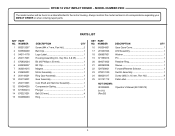
... 2 16 642654001 Gear Case Cover 1 2 633586009 Belt Clip 1 17 291207003 LED Assembly 1 3 940114178 Logo Label 1 18 636867001 Washer 1 4 204117001 Housing Assembly (Inc. PARTS LIST KEY PART KEY PART NO. Key Nos. 3 & 25 1 19 671565013 Pin 1 5 670802034 Bit (#2 Phillips x 50 mm 1 20 694074002 Retainer Ring 1 6 630206007 Bit Clip 1 21 690260058 Sleeve 1 7 303001015 Magnet 1 22 529700001 Forward/Reverse Selector 1 8 230605001 Motor Assembly 1 23 270013150 Switch Assembly 1 9 204148001 Ring Gear Assembly 1 24 660031017 Screw (M3.5 x 16...
... 2 16 642654001 Gear Case Cover 1 2 633586009 Belt Clip 1 17 291207003 LED Assembly 1 3 940114178 Logo Label 1 18 636867001 Washer 1 4 204117001 Housing Assembly (Inc. PARTS LIST KEY PART KEY PART NO. Key Nos. 3 & 25 1 19 671565013 Pin 1 5 670802034 Bit (#2 Phillips x 50 mm 1 20 694074002 Retainer Ring 1 6 630206007 Bit Clip 1 21 690260058 Sleeve 1 7 303001015 Magnet 1 22 529700001 Forward/Reverse Selector 1 8 230605001 Motor Assembly 1 23 270013150 Switch Assembly 1 9 204148001 Ring Gear Assembly 1 24 660031017 Screw (M3.5 x 16...
User Manual 2
Page 4
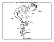
RYOBI 18 VOLT IMPACT DRIVER − MODEL NUMBER P290 TRI-BEAM LED MOTOR BLACK CIRCUIT BOARD RED SWITCH BLACK RED CONTACT PLATE WIRING DIAGRAM 4
RYOBI 18 VOLT IMPACT DRIVER − MODEL NUMBER P290 TRI-BEAM LED MOTOR BLACK CIRCUIT BOARD RED SWITCH BLACK RED CONTACT PLATE WIRING DIAGRAM 4


