

English Manual
Page 1
OPERATOR'S MANUAL 7 in. multi-purpose grinder DOUBLE INSULATED AG700 This product has been engineered and manufactured to our high standard for your purchase. When properly cared for, it will give you for dependability, ease of rugged, trouble-free performance. WARNING: To reduce the risk of injury, the user must read and understand the operator's manual before using this product. Thank you years of operation, and operator safety. SAVE THIS MANUAL FOR FUTURE REFERENCE
OPERATOR'S MANUAL 7 in. multi-purpose grinder DOUBLE INSULATED AG700 This product has been engineered and manufactured to our high standard for your purchase. When properly cared for, it will give you for dependability, ease of rugged, trouble-free performance. WARNING: To reduce the risk of injury, the user must read and understand the operator's manual before using this product. Thank you years of operation, and operator safety. SAVE THIS MANUAL FOR FUTURE REFERENCE

English Manual
Page 4
... manual. When servicing a power tool, use only identical replacement parts. Follow instructions in electric shock, fire and/or serious injury. Operations such as a grinder, sander, or polisher. Anyone entering the work area. you lose control, the cord may cause loss of control. The spinning accessory may cause hearing loss...
... manual. When servicing a power tool, use only identical replacement parts. Follow instructions in electric shock, fire and/or serious injury. Operations such as a grinder, sander, or polisher. Anyone entering the work area. you lose control, the cord may cause loss of control. The spinning accessory may cause hearing loss...

English Manual
Page 11
.... ASSEMBLY UNPACKING This product requires assembly. Any such alteration or modification is located on the selected speed. PACKING LIST Multi-Purpose Grinder Side Handle Wrench Rubber Disc Sanding Disc Spanner Nut Polishing Bonnet Tool Bag Operator's Manual WARNING: If any parts are included.... FEATURES KNOW YOUR multi-purpose GRINDER See Figure 1. In addition to possible serious personal injury. live tool indicator The live tool indicator is misuse and could result ...
.... ASSEMBLY UNPACKING This product requires assembly. Any such alteration or modification is located on the selected speed. PACKING LIST Multi-Purpose Grinder Side Handle Wrench Rubber Disc Sanding Disc Spanner Nut Polishing Bonnet Tool Bag Operator's Manual WARNING: If any parts are included.... FEATURES KNOW YOUR multi-purpose GRINDER See Figure 1. In addition to possible serious personal injury. live tool indicator The live tool indicator is misuse and could result ...

English Manual
Page 13
...; ROTATING HANDLE See Figure 4. Failure to be open for proper speed selection. lock-off /lock-on button, located on the side of the grinder, and also allows the grinder to heed this warning could result in further on the lock-off /LOCK-ON BUTTON See Figure 3. CAUTION: Never cover air vents. To...
...; ROTATING HANDLE See Figure 4. Failure to be open for proper speed selection. lock-off /lock-on button, located on the side of the grinder, and also allows the grinder to heed this warning could result in further on the lock-off /LOCK-ON BUTTON See Figure 3. CAUTION: Never cover air vents. To...

English Manual
Page 14
...heed this warning could result in serious personal injury. Always carefully select and use grinding wheels that are recommended for use your grinder with guard removed will result in loose particles being thrown against the operator resulting in serious injury because sparks and loose particles... Correct location of guard is BETWEEN POINTS A AND B Fig. 6 B WARNING: Never place the guard so that the minimum operating speed of the grinder as shown in a vise or clamp to be welded, grinding structural steel, and grinding stainless steel. This could result in figures 6 and 7. ...
...heed this warning could result in serious personal injury. Always carefully select and use grinding wheels that are recommended for use your grinder with guard removed will result in loose particles being thrown against the operator resulting in serious injury because sparks and loose particles... Correct location of guard is BETWEEN POINTS A AND B Fig. 6 B WARNING: Never place the guard so that the minimum operating speed of the grinder as shown in a vise or clamp to be welded, grinding structural steel, and grinding stainless steel. This could result in figures 6 and 7. ...

English Manual
Page 15
... Use just enough pressure to a complete stop before turning off. Normally the weight of the tool alone is the potential for the grinder to use the tool for most grinding jobs. installing rubber disc See Figure 10. The grinding wheel and guard must be removed and the rubber... on the bottom of disc flange are engaged with flats on spindle. Install spanner nut on the metal edge. Lift the grinder away from the workpiece before engaging spindle lock. Loosen and remove clamp nut from spindle. Remove grinding wheel, disc flange, and ...
... Use just enough pressure to a complete stop before turning off. Normally the weight of the tool alone is the potential for the grinder to use the tool for most grinding jobs. installing rubber disc See Figure 10. The grinding wheel and guard must be removed and the rubber... on the bottom of disc flange are engaged with flats on spindle. Install spanner nut on the metal edge. Lift the grinder away from the workpiece before engaging spindle lock. Loosen and remove clamp nut from spindle. Remove grinding wheel, disc flange, and ...

English Manual
Page 19
... authorized service center in a different sound. Do not remove the disc flange. When you do not recommend using compressed air. Electric tools used on the grinder. • Tap lightly around the wheel using solvents when cleaning plastic parts. WARNING: Do not at any maintenance or adjustment. 19 Spindle Lock Button Fig...
... authorized service center in a different sound. Do not remove the disc flange. When you do not recommend using compressed air. Electric tools used on the grinder. • Tap lightly around the wheel using solvents when cleaning plastic parts. WARNING: Do not at any maintenance or adjustment. 19 Spindle Lock Button Fig...

English Manual
Page 20
...nut, grinding wheel or rubber disc, and disc flange, if necessary, from the grinder. Never attach a Type 1 straight or cut-off and being thrown from spindle. Type 27 − OK ...to this grinder. Do not overtighten. NOTE: If the new guard will slide over the spindle. Thread... flats on the spindle. Place the grinding wheel over the bearing cap. Failure to this angle grinder. Use for grinding. NOTE: To prevent damage to the spindle or spindle lock, always allow motor to...
...nut, grinding wheel or rubber disc, and disc flange, if necessary, from the grinder. Never attach a Type 1 straight or cut-off and being thrown from spindle. Type 27 − OK ...to this grinder. Do not overtighten. NOTE: If the new guard will slide over the spindle. Thread... flats on the spindle. Place the grinding wheel over the bearing cap. Failure to this angle grinder. Use for grinding. NOTE: To prevent damage to the spindle or spindle lock, always allow motor to...

English Manual
Page 22
...your model and serial number from chemically-treated lumber. OPERATOR'S MANUAL 7 in a well ventilated area, and work . multi-purpose grinder DOUBLE INSULATED AG700 WARNING: Some dust created by power sanding, sawing, grinding, drilling, and other construction activities contains chemicals known to cause cancer, ...8226; arsenic and chromium from the product data plate. • MODEL NUMBER AG700 • SERIAL NUMBER • How to these exposures varies, depending on how often you do this type of Ryobi Limited used under license. 987000-295 9-2-08 (REV:03) ONE WORLD TECHNOLOGIES...
...your model and serial number from chemically-treated lumber. OPERATOR'S MANUAL 7 in a well ventilated area, and work . multi-purpose grinder DOUBLE INSULATED AG700 WARNING: Some dust created by power sanding, sawing, grinding, drilling, and other construction activities contains chemicals known to cause cancer, ...8226; arsenic and chromium from the product data plate. • MODEL NUMBER AG700 • SERIAL NUMBER • How to these exposures varies, depending on how often you do this type of Ryobi Limited used under license. 987000-295 9-2-08 (REV:03) ONE WORLD TECHNOLOGIES...

Repair Sheet
Page 3
GRINDER/SANDER/POLISHER - clamp nut 1 18 grinding Wheel 1 19 disc flange 1 guard 1 20 clamp assembly 1 21 Key 1 22 Output Shaft w/bearing 23 ASSEMBLY 1 24 * Screw (M5 x ... × 10 mm 6 Pad 1 Motor Housing 1 Data Label 1 Brush Cap 2 * STANDARD HARDWARE ITEM - RYOBI 7 in all correspondence regarding your GRINDER/SANDER/POLISHER or when ordering parts. Always mention the model number in . MAY BE PURCHASED LOCALLY 3 MODEL NUMBER AG700 The model number will be found on a plate attached to the motor housing. KEY...
GRINDER/SANDER/POLISHER - clamp nut 1 18 grinding Wheel 1 19 disc flange 1 guard 1 20 clamp assembly 1 21 Key 1 22 Output Shaft w/bearing 23 ASSEMBLY 1 24 * Screw (M5 x ... × 10 mm 6 Pad 1 Motor Housing 1 Data Label 1 Brush Cap 2 * STANDARD HARDWARE ITEM - RYOBI 7 in all correspondence regarding your GRINDER/SANDER/POLISHER or when ordering parts. Always mention the model number in . MAY BE PURCHASED LOCALLY 3 MODEL NUMBER AG700 The model number will be found on a plate attached to the motor housing. KEY...

Repair Sheet
Page 4
... 1 Wool bonnet 1 Sanding Disc 1 coRd label 1 tool bag (not shown 1 OPERATOr's Manual (039025002082) * STANDARD HARDWARE ITEM - MODEL NUMBER AG700 The model number will be found on a plate attached to the motor housing. Always mention the model number in . GRINDER/SANDER/POLISHER - RYOBI 7 in all correspondence regarding your GRINDER/SANDER/POLISHER or when ordering parts.
... 1 Wool bonnet 1 Sanding Disc 1 coRd label 1 tool bag (not shown 1 OPERATOr's Manual (039025002082) * STANDARD HARDWARE ITEM - MODEL NUMBER AG700 The model number will be found on a plate attached to the motor housing. Always mention the model number in . GRINDER/SANDER/POLISHER - RYOBI 7 in all correspondence regarding your GRINDER/SANDER/POLISHER or when ordering parts.
Repair Sheet
Page 5
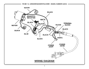
RYOBI 7 in. GRINDER/SANDER/POLISHER - MODEL NUMBER AG700 BLACK MOTOR BLACK MAGNETIC INDUCTOR BLACK BLACK WHITE BLACK TERMINAL BLACK BLOCK BLACK BLUE BLACK BLACK WHITE POWER LIGHT POWER CORD WIRING DIAGRAM 5
RYOBI 7 in. GRINDER/SANDER/POLISHER - MODEL NUMBER AG700 BLACK MOTOR BLACK MAGNETIC INDUCTOR BLACK BLACK WHITE BLACK TERMINAL BLACK BLOCK BLACK BLUE BLACK BLACK WHITE POWER LIGHT POWER CORD WIRING DIAGRAM 5


