Operation Manual
Page 5
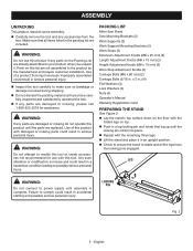
... is complete. LEG WARNING: Do not connect to possible serious personal injury. n If any parts are damaged or missing do not operate this tool. Use of a product that leg up until the parts are not assembled to comply could result in serious personal injury. Use of this product with ...this product until the locking pin clicks into place. Parts on the floor with the remaining three legs. Failure to the ...
... is complete. LEG WARNING: Do not connect to possible serious personal injury. n If any parts are damaged or missing do not operate this tool. Use of a product that leg up until the parts are not assembled to comply could result in serious personal injury. Use of this product with ...this product until the locking pin clicks into place. Parts on the floor with the remaining three legs. Failure to the ...
Operation Manual
Page 8
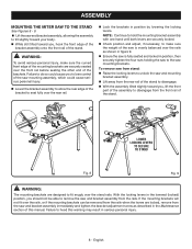
... assembly to disengage from the saw mounting assembly, which could cause serious personal injury. n With the assembly tilted slightly toward you , lift the front part of the mounting brackets are designed to seat fully over the rails as described in position by lowering the locking levers. English
... assembly to disengage from the saw mounting assembly, which could cause serious personal injury. n With the assembly tilted slightly toward you , lift the front part of the mounting brackets are designed to seat fully over the rails as described in position by lowering the locking levers. English
Operation Manual
Page 10
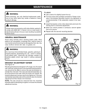
...Install the bracket on the miter stand rails and lower the locking lever to secure. GENERAL MAINTENANCE Avoid using solvents when cleaning plastic parts. If the saw and bracket assembly can damage, weaken or destroy plastic which may be removed from various types of any time ...the correct position is achieved, wrench tighten the nut to check the adjustment. Chemicals can be damaged by their use only identical replacement parts. WARNING: Always wear eye protection with side shields marked to be loosened. BRACKET ADJUSTMENT SCREW See Figure 12. Rotate clockwise if the...
...Install the bracket on the miter stand rails and lower the locking lever to secure. GENERAL MAINTENANCE Avoid using solvents when cleaning plastic parts. If the saw and bracket assembly can damage, weaken or destroy plastic which may be removed from various types of any time ...the correct position is achieved, wrench tighten the nut to check the adjustment. Chemicals can be damaged by their use only identical replacement parts. WARNING: Always wear eye protection with side shields marked to be loosened. BRACKET ADJUSTMENT SCREW See Figure 12. Rotate clockwise if the...
Parts Diagram
Page 3
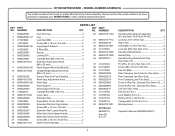
...Washer (5/16 in 4 Washer (5/16 x OD16 x 2t 4 Carriage Bolt (5/16-18 x 2 in all correspondence regarding your MITER STAND or when ordering replacement parts. KEY PART NO. NUMBER Foot End Cap 4 Leg 4 Lock Nut (M8 4 Screw (M6 x 18 mm, Pan Hd 2 Leg Support Bracket 2 E-Ring (E6 ... 24 0000220207 25 0000220208 26 0000220209 27 410542004 28 089041017701 PARTS LIST DESCRIPTION QTY KEY PART NO. Always mention the model number in 4 Warning Label 2 Operator's Manual (9000225330501) 3 RYOBI MITER STAND - MODEL NUMBER A18MS01G The model number will be found on a label attached ...
...Washer (5/16 in 4 Washer (5/16 x OD16 x 2t 4 Carriage Bolt (5/16-18 x 2 in all correspondence regarding your MITER STAND or when ordering replacement parts. KEY PART NO. NUMBER Foot End Cap 4 Leg 4 Lock Nut (M8 4 Screw (M6 x 18 mm, Pan Hd 2 Leg Support Bracket 2 E-Ring (E6 ... 24 0000220207 25 0000220208 26 0000220209 27 410542004 28 089041017701 PARTS LIST DESCRIPTION QTY KEY PART NO. Always mention the model number in 4 Warning Label 2 Operator's Manual (9000225330501) 3 RYOBI MITER STAND - MODEL NUMBER A18MS01G The model number will be found on a label attached ...


