Operation Manual
Page 2
... and understand this operator's manual, the operator's manual for the table saw and all Ryobi miter saws or slide miter saws with a blade diameter not larger than 12 in., or for other than 12 in . English WARNING: This stand is designed to prevent misuse of the miter saw and workpiece together must not exceed 400 pounds. Do not...
... and understand this operator's manual, the operator's manual for the table saw and all Ryobi miter saws or slide miter saws with a blade diameter not larger than 12 in., or for other than 12 in . English WARNING: This stand is designed to prevent misuse of the miter saw and workpiece together must not exceed 400 pounds. Do not...
Operation Manual
Page 5
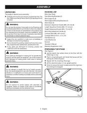
... not discard the packing material until the parts are already assembled to power supply until the locking pin clicks into place. PACKING LIST Miter Saw Stand Saw Mounting Brackets (2) Work Supports (2) Work Support Mounting Brackets (2) Work Stops (2) Extension Adjustment Knobs (M8 x 25 mm) (2) Length...x 60 mm) (2) Carriage Bolts (5/16 in .) (4) Flat Washers (4) Lock Washers (4) Nuts (4) Operator's Manual Warranty Registration Card PREPARING THE STAND See Figure 2. x 2 in . LEG WARNING: Do not connect to your product when you have the locking pins engaged. n Check to ...
... not discard the packing material until the parts are already assembled to power supply until the locking pin clicks into place. PACKING LIST Miter Saw Stand Saw Mounting Brackets (2) Work Supports (2) Work Support Mounting Brackets (2) Work Stops (2) Extension Adjustment Knobs (M8 x 25 mm) (2) Length...x 60 mm) (2) Carriage Bolts (5/16 in .) (4) Flat Washers (4) Lock Washers (4) Nuts (4) Operator's Manual Warranty Registration Card PREPARING THE STAND See Figure 2. x 2 in . LEG WARNING: Do not connect to your product when you have the locking pins engaged. n Check to ...
Operation Manual
Page 8
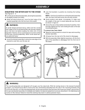
...the brackets. NOTE: Continue to seat fully over the rear rail. To remove saw from stand: n Raise the locking levers to unlock the saw and mounting bracket assembly. n Lift away from the saw is fully seated and locked in position, then securely tighten the four nuts ...18 19 20 21 22 23 LOWER LOCKING LEVERS TO SECURE TO STAND Fig. 8 Fig. 9 WARNING: The mounting brackets are securely seated over the stand rails. ASSEMBLY MOUNTING THE MITER SAW TO THE STAND See Figures 8 - 9. n Lift the saw mounting brackets. n Lower the bracket assembly to heed this manual...
...the brackets. NOTE: Continue to seat fully over the rear rail. To remove saw from stand: n Raise the locking levers to unlock the saw and mounting bracket assembly. n Lift away from the saw is fully seated and locked in position, then securely tighten the four nuts ...18 19 20 21 22 23 LOWER LOCKING LEVERS TO SECURE TO STAND Fig. 8 Fig. 9 WARNING: The mounting brackets are securely seated over the stand rails. ASSEMBLY MOUNTING THE MITER SAW TO THE STAND See Figures 8 - 9. n Lift the saw mounting brackets. n Lower the bracket assembly to heed this manual...
Operation Manual
Page 10
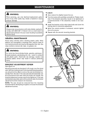
...Use a wrench to check the adjustment. SAW MOUNTING BRACKET WRENCH WARNING: Do not at any other parts may be able to be loosened. Use of commercial solvents and may create a hazard or cause product damage. n Install the bracket on the miter stand rails and lower the locking lever to... slightly loosen the nut. English Rotate clockwise if the bracket assembly needs to be tightened or counterclockwise if the assembly needs to remove the saw should not be damaged by their use...
...Use a wrench to check the adjustment. SAW MOUNTING BRACKET WRENCH WARNING: Do not at any other parts may be able to be loosened. Use of commercial solvents and may create a hazard or cause product damage. n Install the bracket on the miter stand rails and lower the locking lever to... slightly loosen the nut. English Rotate clockwise if the bracket assembly needs to be tightened or counterclockwise if the assembly needs to remove the saw should not be damaged by their use...
Parts Diagram
Page 3
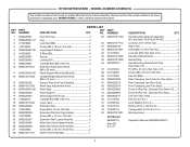
... 4 Extension Rail Locator Bracket 2 Miter Saw Stand Upper Handle 1 Miter Saw Stand Lower Handle 1 Screw (M4 x 16 mm, Truss Hd 2 Not Shown: 983000710 (Rev:05) 8-7-19 Work Frame Assembly 1 DESCRIPTION QTY Saw Mounting Bracket Assembly (Inc. KEY PART NO. RYOBI MITER STAND - Always mention the model number in 4 Warning Label 2 Operator's Manual (9000225330501) 3 MODEL NUMBER A18MS01G The model number will be...
... 4 Extension Rail Locator Bracket 2 Miter Saw Stand Upper Handle 1 Miter Saw Stand Lower Handle 1 Screw (M4 x 16 mm, Truss Hd 2 Not Shown: 983000710 (Rev:05) 8-7-19 Work Frame Assembly 1 DESCRIPTION QTY Saw Mounting Bracket Assembly (Inc. KEY PART NO. RYOBI MITER STAND - Always mention the model number in 4 Warning Label 2 Operator's Manual (9000225330501) 3 MODEL NUMBER A18MS01G The model number will be...


