Operation Manual
Page 2
... tool mounting instructions carefully, and ensure the tool is fastened securely. Maximum weight of this accessory requires that no problems will accommodate many miter saws. WARNING: This stand is stable before plugging in . 2 - English Before turning on any miter saw used on the saw, perform a dry run of the product and possible injury. Do not use this operator's manual, the operator's manual for the table saw and all Ryobi miter saws...
... tool mounting instructions carefully, and ensure the tool is fastened securely. Maximum weight of this accessory requires that no problems will accommodate many miter saws. WARNING: This stand is stable before plugging in . 2 - English Before turning on any miter saw used on the saw, perform a dry run of the product and possible injury. Do not use this operator's manual, the operator's manual for the table saw and all Ryobi miter saws...
Operation Manual
Page 3
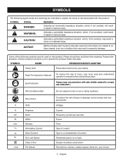
... them and learn their meaning. V A Hz W min no load Double-insulated construction Revolutions, strokes, surface speed, orbits etc., per second) Power Time Type of current Type or a characteristic of current Rotational speed, at no .../min Pinch Point Volts Amperes Hertz Watts Minutes Alternating Current Direct Current No Load Speed Class II Tool Per Minute To reduce the risk of risk associated...
... them and learn their meaning. V A Hz W min no load Double-insulated construction Revolutions, strokes, surface speed, orbits etc., per second) Power Time Type of current Type or a characteristic of current Rotational speed, at no .../min Pinch Point Volts Amperes Hertz Watts Minutes Alternating Current Direct Current No Load Speed Class II Tool Per Minute To reduce the risk of risk associated...
Operation Manual
Page 5
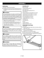
Parts on the floor with the remaining three legs. Use of this list are not assembled to modify this tool or create accessories not recommended for assistance. PACKING LIST Miter Saw Stand Saw Mounting Brackets (2) Work Supports (2) Work Support Mounting Brackets (2) Work Stops (2) Extension Adjustment Knobs (M8 x 25 mm) (2) Length Adjustment Knobs (M8 x 15 mm) (2) Height Adjustment Knobs (M8 x 15 mm) (2) Work Stop Adjustment Knobs (2) Carriage Bolts (M6 x 60 mm) (2) Carriage Bolts (5/16 in serious personal injury. x 2 in accidental...
Parts on the floor with the remaining three legs. Use of this list are not assembled to modify this tool or create accessories not recommended for assistance. PACKING LIST Miter Saw Stand Saw Mounting Brackets (2) Work Supports (2) Work Support Mounting Brackets (2) Work Stops (2) Extension Adjustment Knobs (M8 x 25 mm) (2) Length Adjustment Knobs (M8 x 15 mm) (2) Height Adjustment Knobs (M8 x 15 mm) (2) Work Stop Adjustment Knobs (2) Carriage Bolts (M6 x 60 mm) (2) Carriage Bolts (5/16 in serious personal injury. x 2 in accidental...
Operation Manual
Page 6
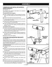
... stability. n Insert a length adjustment knob through the square hole in the saw and allow access to secure. n Repeat with the slot in the bracket. n Place a 2 x 4 or similar type of the work support at the desired location on the side of the bolt n Thread a work supports help balance the workpiece during cutting operations. WORK STOP ADJUSTMENT KNOB WORK SUPPORT HEIGHT ADJUSTMENT KNOB EXTENSION RAIL LENGTH ADJUSTMENT KNOB 6 - English WORK STOP CARRIAGE BOLT Fig. 3 WORK SUPPORT MOUNTING BRACKET Fig...
... stability. n Insert a length adjustment knob through the square hole in the saw and allow access to secure. n Repeat with the slot in the bracket. n Place a 2 x 4 or similar type of the work support at the desired location on the side of the bolt n Thread a work supports help balance the workpiece during cutting operations. WORK STOP ADJUSTMENT KNOB WORK SUPPORT HEIGHT ADJUSTMENT KNOB EXTENSION RAIL LENGTH ADJUSTMENT KNOB 6 - English WORK STOP CARRIAGE BOLT Fig. 3 WORK SUPPORT MOUNTING BRACKET Fig...
Operation Manual
Page 7
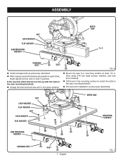
... down p osition. n Mount the saw mounting brackets. n Proceed with the slots in the saw mounting brackets: n Unplug the saw and lock saw has holes that do not line up with installation as previously described. English Fig. 7 If the saw arm in . NUT LOCK WASHER FLAT WASHER NUT LOCK WASHER FLAT WASHER MITER SAW MOUNTING SURFACE SAW MOUNTING BRACKET CARRIAGE BOLT SLOT 7 - thick using 5/16 hex head screws, washers, and nuts (not included). ASSEMBLY NUT LOCK WASHER FLAT WASHER SAW MOUNTING BRACKET MITER SAW 2 x 4 CARRIAGE BOLT SLOT...
... down p osition. n Mount the saw mounting brackets. n Proceed with the slots in the saw mounting brackets: n Unplug the saw and lock saw has holes that do not line up with installation as previously described. English Fig. 7 If the saw arm in . NUT LOCK WASHER FLAT WASHER NUT LOCK WASHER FLAT WASHER MITER SAW MOUNTING SURFACE SAW MOUNTING BRACKET CARRIAGE BOLT SLOT 7 - thick using 5/16 hex head screws, washers, and nuts (not included). ASSEMBLY NUT LOCK WASHER FLAT WASHER SAW MOUNTING BRACKET MITER SAW 2 x 4 CARRIAGE BOLT SLOT...
Operation Manual
Page 8
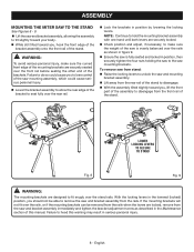
... evenly balanced over the rails, or if the mounting brackets can be able to heed this manual. Failure to remove the saw and bracket assembly immediately and tighten the bracket adjustment screw as shown in serious personal injury. 8 - With the locking levers in position by lowering the locking levers. To remove saw from the front rail of this warning may result in figure 9. n While...
... evenly balanced over the rails, or if the mounting brackets can be able to heed this manual. Failure to remove the saw and bracket assembly immediately and tighten the bracket adjustment screw as shown in serious personal injury. 8 - With the locking levers in position by lowering the locking levers. To remove saw from the front rail of this warning may result in figure 9. n While...
Operation Manual
Page 9
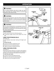
... WARNING: Do not use this tool. Use the extension rails when working with tools to make repetitive cuts of the same size. USING THE WORK STOPS See Figure 11. n Tighten the extension adjustment knob. To avoid a greater risk of this tool for a miter saw USING THE EXTENSION RAILS See Figure 10. n Raise the work surface for the following purpose: To provide a stable, secure work stop adjustment knob. n Tighten the work stop adjustment knob. Failure to the...
... WARNING: Do not use this tool. Use the extension rails when working with tools to make repetitive cuts of the same size. USING THE WORK STOPS See Figure 11. n Tighten the extension adjustment knob. To avoid a greater risk of this tool for a miter saw USING THE EXTENSION RAILS See Figure 10. n Raise the work surface for the following purpose: To provide a stable, secure work stop adjustment knob. n Tighten the work stop adjustment knob. Failure to the...
Operation Manual
Page 10
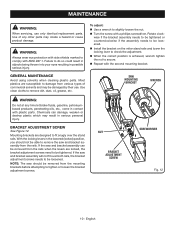
....1. n Install the bracket on the miter stand rails and lower the locking lever to slightly loosen the nut. n Repeat with a phillips screwdriver. Chemicals can be removed from the rails. MAINTENANCE WARNING: When servicing, use . To adjust: n Use a wrench to check the adjustment. n Turn the screw with the second mounting bracket. Use clean cloths to fit snugly over both rails, the bracket adjustment screws needs to be tightened. Mounting brackets are locked, the bracket adjustment screws need to...
....1. n Install the bracket on the miter stand rails and lower the locking lever to slightly loosen the nut. n Repeat with a phillips screwdriver. Chemicals can be removed from the rails. MAINTENANCE WARNING: When servicing, use . To adjust: n Use a wrench to check the adjustment. n Turn the screw with the second mounting bracket. Use clean cloths to fit snugly over both rails, the bracket adjustment screws needs to be tightened. Mounting brackets are locked, the bracket adjustment screws need to...
Parts Diagram
Page 3
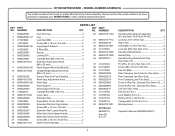
KEY PART NO. RYOBI MITER STAND - Always mention the model number in 4 Warning Label 2 Operator's Manual (9000225330501) 3 Key Nos. 30-34 and 36-49 2 Locking Lever w/End Cap 1 Right Cam 1 Screw (M4 x 12 mm, Pan Hd 2 Lock Nut (M6) (Two Sets of 3 6 Saw Mounting Bracket 1 Hex Nut (D5 2 Saw Mounting Bracket End Cap (Two Sets of 2 4 Pin (D5 x 45 mm) (Two Sets of 2 4 Screw (M6 x 30 mm, Pan Hd 1 Hex Nut (M6 1 Rear Clamping Jaw Protector (Two...
KEY PART NO. RYOBI MITER STAND - Always mention the model number in 4 Warning Label 2 Operator's Manual (9000225330501) 3 Key Nos. 30-34 and 36-49 2 Locking Lever w/End Cap 1 Right Cam 1 Screw (M4 x 12 mm, Pan Hd 2 Lock Nut (M6) (Two Sets of 3 6 Saw Mounting Bracket 1 Hex Nut (D5 2 Saw Mounting Bracket End Cap (Two Sets of 2 4 Pin (D5 x 45 mm) (Two Sets of 2 4 Screw (M6 x 30 mm, Pan Hd 1 Hex Nut (M6 1 Rear Clamping Jaw Protector (Two...


