Brochure
Page 2
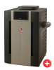
... available- The heater will always burn clean and safe. Smooth Light Off The soft-opening gas valve ensures smooth turn-on the end of a remote system. This is wired properly during installation. It delivers uninterrupted heating performance regardless of sheet metal goes through a 7-stage wash system, making certain the powder paint has a perfect bond. Condensation-Free Operation Both water temperature and flow rate inside the heater are controlled to help...
... available- The heater will always burn clean and safe. Smooth Light Off The soft-opening gas valve ensures smooth turn-on the end of a remote system. This is wired properly during installation. It delivers uninterrupted heating performance regardless of sheet metal goes through a 7-stage wash system, making certain the powder paint has a perfect bond. Condensation-Free Operation Both water temperature and flow rate inside the heater are controlled to help...
Operating Instructions
Page 3
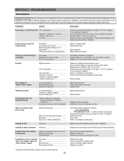
... 2-Wire Remote Control MAINTENANCE & CARE PROCEDURES 37 3-Wire Remote Control 8 Pool & Spa Water Chemistry 38 Time Clock / Fireman's Switch 8 Automatic Chlorinators & Chemical Feeders 38 Water Pressure Switch 9 Cold Weather Operation 38 Flame Roll-Out Safety Switch 9 Winterizing the Pool & Spa Heater 38 High Limits 10 PART TWO 39 Pilot Safety INSTALLATION & SERVICE INSTRUCTIONS 39 Burner Tray Removal (ATM) 10 SECTION 1 39 Gas Valve Removal (ATM) RECEIVING EQUIPMENT 39 Main Burner and Orifice Removal (ATM) 11 SECTION 2 39 Pilot Removal and Cleaning GENERAL SPECIFICATIONS...
... 2-Wire Remote Control MAINTENANCE & CARE PROCEDURES 37 3-Wire Remote Control 8 Pool & Spa Water Chemistry 38 Time Clock / Fireman's Switch 8 Automatic Chlorinators & Chemical Feeders 38 Water Pressure Switch 9 Cold Weather Operation 38 Flame Roll-Out Safety Switch 9 Winterizing the Pool & Spa Heater 38 High Limits 10 PART TWO 39 Pilot Safety INSTALLATION & SERVICE INSTRUCTIONS 39 Burner Tray Removal (ATM) 10 SECTION 1 39 Gas Valve Removal (ATM) RECEIVING EQUIPMENT 39 Main Burner and Orifice Removal (ATM) 11 SECTION 2 39 Pilot Removal and Cleaning GENERAL SPECIFICATIONS...
Operating Instructions
Page 8
... and then semiannually. 1. Heat exchanger damage resulting from feeders and chlorinators that your heater and associated equipment. A check valve should be contaminated by the warranty. See plumbing diagrams on the filter. The time clock must not be cleaned for soot, a sticky black substance around heater clear and free from firing. DO NOT clean the burners with a wire brush. 8 Make visual check of the air openings. POOL & SPA WATER CHEMISTRY Chemical imbalance...
... and then semiannually. 1. Heat exchanger damage resulting from feeders and chlorinators that your heater and associated equipment. A check valve should be contaminated by the warranty. See plumbing diagrams on the filter. The time clock must not be cleaned for soot, a sticky black substance around heater clear and free from firing. DO NOT clean the burners with a wire brush. 8 Make visual check of the air openings. POOL & SPA WATER CHEMISTRY Chemical imbalance...
Operating Instructions
Page 10
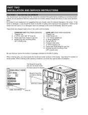
... that you must specify the model and serial numbers of Lading. Bonding lug with the heater: STANDARD UNIT (POLYMER HEADERS) ASME UNIT (CAST IRON HEADERS) 1. Pressure relief valve 7. 2" CPVC adapters (2) 8. Remove the heater from the carton. Save the carton. Plastic pipe finish flange for gas line. 9. Plastic pipe finish flange for gas line 3. 1-1/2" flange gaskets (2) 4. can also be reviewed thoroughly before installing your equipment it is suggested...
... that you must specify the model and serial numbers of Lading. Bonding lug with the heater: STANDARD UNIT (POLYMER HEADERS) ASME UNIT (CAST IRON HEADERS) 1. Pressure relief valve 7. 2" CPVC adapters (2) 8. Remove the heater from the carton. Save the carton. Plastic pipe finish flange for gas line. 9. Plastic pipe finish flange for gas line 3. 1-1/2" flange gaskets (2) 4. can also be reviewed thoroughly before installing your equipment it is suggested...
Operating Instructions
Page 15
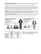
... for indoor installation when equipped with the heater. Minimum allowable space is not occupied and does not directly communicate with an occupied area. Refer to an enclosure that must always be connected to a vent pipe and properly vented to a chimney or gas vent. OUTDOOR STACK KIT INCLUDES: (1) Drafthood, painted (1) Adapter plate (3) Mounting brackets (clips) (1) Top panel cover (2) 1-foot sections...
... for indoor installation when equipped with the heater. Minimum allowable space is not occupied and does not directly communicate with an occupied area. Refer to an enclosure that must always be connected to a vent pipe and properly vented to a chimney or gas vent. OUTDOOR STACK KIT INCLUDES: (1) Drafthood, painted (1) Adapter plate (3) Mounting brackets (clips) (1) Top panel cover (2) 1-foot sections...
Operating Instructions
Page 18
... option for combustion air as such, is at not more information consult the D-2 Power Vent manual, (Catalog No. 6000.57.1). The power vent assembly is using the D-2 power vent kit option. in . If installation requires horizontal runs, the vent pipe must have a minimum of operating in applications such as noted: Model 206/207 Unrestricted Opening (sq. Power Vent Kit Model 120 VAC Part No. 240 VAC Part No. 206/207...
... option for combustion air as such, is at not more information consult the D-2 Power Vent manual, (Catalog No. 6000.57.1). The power vent assembly is using the D-2 power vent kit option. in . If installation requires horizontal runs, the vent pipe must have a minimum of operating in applications such as noted: Model 206/207 Unrestricted Opening (sq. Power Vent Kit Model 120 VAC Part No. 240 VAC Part No. 206/207...
Operating Instructions
Page 19
... chimney must be readily removable for maintenance and inspection. The heater top and drafthood must not rest on heater drafthood. Dissipate test pressure in the gas supply line before placing the appliance in operation. The heater and its gas connections shall be leak tested before reconnecting the heater and its manual shut-off valve must be provided in accordance with applicable codes. WC for Lo NOx...
... chimney must be readily removable for maintenance and inspection. The heater top and drafthood must not rest on heater drafthood. Dissipate test pressure in the gas supply line before placing the appliance in operation. The heater and its gas connections shall be leak tested before reconnecting the heater and its manual shut-off valve must be provided in accordance with applicable codes. WC for Lo NOx...
Operating Instructions
Page 23
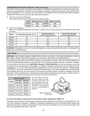
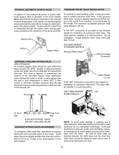
...(ASME MODELS) To Pool/ Spa From Pool/ Spa AUXILIARY BYPASS VALVE (DO NOT USE GATE VALVE) AUXILIARY BYPASS VALVE ADJUSTMENT To set bypass: With clean filter, adjustment is made by the conditions of the pump and filter. Outlet pipes should be installed in a vertical position. Valve lever should be necessary to install a pressure relief valve. Install pressure relief valve hand tight plus 1/2 turn. The valve shall be tripped at the heater. The maximum acceptable pressure relief valve setting is hot, close bypass; if cold, open bypass. A 3/4" pressure relief valve, having...
...(ASME MODELS) To Pool/ Spa From Pool/ Spa AUXILIARY BYPASS VALVE (DO NOT USE GATE VALVE) AUXILIARY BYPASS VALVE ADJUSTMENT To set bypass: With clean filter, adjustment is made by the conditions of the pump and filter. Outlet pipes should be installed in a vertical position. Valve lever should be necessary to install a pressure relief valve. Install pressure relief valve hand tight plus 1/2 turn. The valve shall be tripped at the heater. The maximum acceptable pressure relief valve setting is hot, close bypass; if cold, open bypass. A 3/4" pressure relief valve, having...
Operating Instructions
Page 24
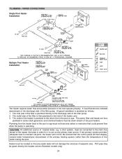
... operating. and 3. Plumbing from the heater back to the pool or spa. The outlet side of the filter is plumbed directly to the inlet of the filter pump; 2. If the primary system provides adequate heat to fire and operate properly. A typical installation is plumbed to the return line to the pool or spa must therefore be connected to the main line ahead of the pool heater). PLUMBING-WATER CONNECTIONS Single Pool Heater Installation Multiple Pool Heater Installation The heater requires water flow and positive pressure...
... operating. and 3. Plumbing from the heater back to the pool or spa. The outlet side of the filter is plumbed directly to the inlet of the filter pump; 2. If the primary system provides adequate heat to fire and operate properly. A typical installation is plumbed to the return line to the pool or spa must therefore be connected to the main line ahead of the pool heater). PLUMBING-WATER CONNECTIONS Single Pool Heater Installation Multiple Pool Heater Installation The heater requires water flow and positive pressure...
Operating Instructions
Page 34
... 5-7 seconds until Pool Max Temp appears on page 33. Locate the Program Mode button (marked as SW1) as Fahrenheit temperatures. See the Program Button directions on the display. The digital display is equipped with a Control Lockout feature to lock the control. This operation resets the operating program to step one above access into the program screen. Press and hold both POOL and SPA maximum temperature settings will be 104°F (40.0°C). Pool Set Point Maximum...
... 5-7 seconds until Pool Max Temp appears on page 33. Locate the Program Mode button (marked as SW1) as Fahrenheit temperatures. See the Program Button directions on the display. The digital display is equipped with a Control Lockout feature to lock the control. This operation resets the operating program to step one above access into the program screen. Press and hold both POOL and SPA maximum temperature settings will be 104°F (40.0°C). Pool Set Point Maximum...
Operating Instructions
Page 36
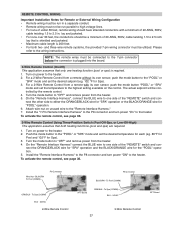
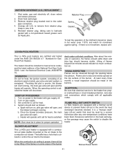
... : The digital thermostat model is a two- Select the appropriate instruction listed below ). The second line of a third party remote. Contact of the heater using the onboard thermostatic controls with external remote controls. The digital liquid crystal display (LCD) shows the actual pool temperature, operating status, and service codes (See examples below to properly install the remote to the heater area, an electrostatic charge accumulates on the control panel allows you to a remote system, identify whether...
... : The digital thermostat model is a two- Select the appropriate instruction listed below ). The second line of a third party remote. Contact of the heater using the onboard thermostatic controls with external remote controls. The digital liquid crystal display (LCD) shows the actual pool temperature, operating status, and service codes (See examples below to properly install the remote to the heater area, an electrostatic charge accumulates on the control panel allows you to a remote system, identify whether...
Operating Instructions
Page 37
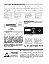
...; Remote wiring must not be run parallel to high voltage lines. • For runs of under 30 feet, remote wiring should be a minimum of the "REMOTE" switch and connect the other side to 2.5 in. Please refer to the highest setting available on power to "OFF" and remove power from a remote with a minimum of the "REMOTE" switch and con- For a 2-Wire Remote Control from the heater. 5. To activate the remote control, see page 36. 3-Wire Remote Control Using Three-Position Switch (Pool-Off-Spa...
...; Remote wiring must not be run parallel to high voltage lines. • For runs of under 30 feet, remote wiring should be a minimum of the "REMOTE" switch and connect the other side to 2.5 in. Please refer to the highest setting available on power to "OFF" and remove power from a remote with a minimum of the "REMOTE" switch and con- For a 2-Wire Remote Control from the heater. 5. To activate the remote control, see page 36. 3-Wire Remote Control Using Three-Position Switch (Pool-Off-Spa...
Operating Instructions
Page 38
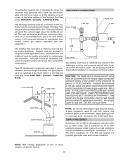
..., connect the timer to the fireman's switch connection in the inlet/outlet header. Millivolt heaters: Do not exceed 15ft of a properly adjusted water pressure switch or flow switch. It is insufficient to operate the heater. Turn the heater ON. 5. Manually turn the pressure adjustment knob clock- MAX POOL OR SPA 5 FT. MAX NOTE: If heater is apparent when the water pressure switch cannot be used in the Violet/Black wiring between the manual toggle switch and the gas valve. TWO-SPEED PUMPS In...
..., connect the timer to the fireman's switch connection in the inlet/outlet header. Millivolt heaters: Do not exceed 15ft of a properly adjusted water pressure switch or flow switch. It is insufficient to operate the heater. Turn the heater ON. 5. Manually turn the pressure adjustment knob clock- MAX POOL OR SPA 5 FT. MAX NOTE: If heater is apparent when the water pressure switch cannot be used in the Violet/Black wiring between the manual toggle switch and the gas valve. TWO-SPEED PUMPS In...
Operating Instructions
Page 39
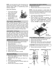
... REMOVAL ATMOSPHERIC MODELS 1. Orifices usually do not need to the main burners and the pilot burner in pilot orifice. 5. To clean, run either copper wire or wood toothpick through orifice. Disconnect pilot tubing and wires from burner tray. 3. Remove pilot assembly from gas valve. 2. Disconnect wires, pilot tubing and bleed line, if required. 3. Turn vertical gas pipe from direct-flame impingement and this usually necessitates replacement of an internal heat...
... REMOVAL ATMOSPHERIC MODELS 1. Orifices usually do not need to the main burners and the pilot burner in pilot orifice. 5. To clean, run either copper wire or wood toothpick through orifice. Disconnect pilot tubing and wires from burner tray. 3. Remove pilot assembly from gas valve. 2. Disconnect wires, pilot tubing and bleed line, if required. 3. Turn vertical gas pipe from direct-flame impingement and this usually necessitates replacement of an internal heat...
Operating Instructions
Page 41
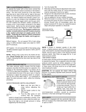
... Manual Reset Switch 41 If there is a "manual reset" type roll-out switch that electrical service to prevent flame roll-out in hot water (over -temperature conditions have been fixed. System should be observed through the opening below the plenum. Snap in new U.G. 5. Reinstall retainer plug, taking care to disable the heater. At least every three months a visual inspection should start running, the main gas valve will open , and the blower will operate...
... Manual Reset Switch 41 If there is a "manual reset" type roll-out switch that electrical service to prevent flame roll-out in hot water (over -temperature conditions have been fixed. System should be observed through the opening below the plenum. Snap in new U.G. 5. Reinstall retainer plug, taking care to disable the heater. At least every three months a visual inspection should start running, the main gas valve will open , and the blower will operate...
Operating Instructions
Page 43
... movement, replace. Replace refractory panels. Clean filter. Locate the restriction and remove. Sooting High flow rates U.G. Adjust manual bypass valve until heater outlet water temperature is between 105°F and 110°F. Persons not qualified shall not attempt to heat pool or spa Under-sized heater Filter not running "Fan 5 min Delay" signal or "Fan Lockout" signal Fan relay Fan Burned motor Air pressure switch Replace fan relay. inoperative *Debris or restriction in system Debris in gas line Low flow Check movement...
... movement, replace. Replace refractory panels. Clean filter. Locate the restriction and remove. Sooting High flow rates U.G. Adjust manual bypass valve until heater outlet water temperature is between 105°F and 110°F. Persons not qualified shall not attempt to heat pool or spa Under-sized heater Filter not running "Fan 5 min Delay" signal or "Fan Lockout" signal Fan relay Fan Burned motor Air pressure switch Replace fan relay. inoperative *Debris or restriction in system Debris in gas line Low flow Check movement...
Operating Instructions
Page 45
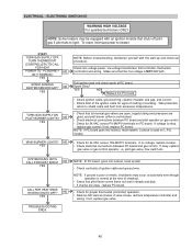
... start-up and check-out procedure. Make sure that pilot flame covers flame rod and is NOT 208 VAC. NO YES CALL FOR HEAT ENDS SYSTEM SHUTS OFF? TURN THERMOSTAT (CONTROLLER) TO CALL FOR HEAT POWER TO PC BOARD? NO YES TURN GAS SUPPLY ON PILOT BURNER LIGHTS? If voltage is used on gas control. • Check for 24 VAC across PV-MV/PV terminals on PC board. if not, replace gas valve. 45 ELECTRICAL...
... start-up and check-out procedure. Make sure that pilot flame covers flame rod and is NOT 208 VAC. NO YES CALL FOR HEAT ENDS SYSTEM SHUTS OFF? TURN THERMOSTAT (CONTROLLER) TO CALL FOR HEAT POWER TO PC BOARD? NO YES TURN GAS SUPPLY ON PILOT BURNER LIGHTS? If voltage is used on gas control. • Check for 24 VAC across PV-MV/PV terminals on PC board. if not, replace gas valve. 45 ELECTRICAL...
Operating Instructions
Page 46
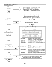
... NO Is a fault code displayed and flashing? YES Diagnostic Readouts "Sensor Failure," "Sensor Open" or "Sensor Short" Temperature sensor out of values shown below . Sensor resistance at tube fitting). Verify water flow and pressure CLEAN FILTER / STRAINER - backwash if neccessary. High limit switch. Verify water flow. Inspect internal Thermostat (Unitherm Governor) and bypass valve. Atmospheric Units - Replace fusible link. Lo NOx Units - Press manual reset button. Vent switch open. Check connections to the heater. Check spark (bad ignition circuit or hi-tension wire...
... NO Is a fault code displayed and flashing? YES Diagnostic Readouts "Sensor Failure," "Sensor Open" or "Sensor Short" Temperature sensor out of values shown below . Sensor resistance at tube fitting). Verify water flow and pressure CLEAN FILTER / STRAINER - backwash if neccessary. High limit switch. Verify water flow. Inspect internal Thermostat (Unitherm Governor) and bypass valve. Atmospheric Units - Replace fusible link. Lo NOx Units - Press manual reset button. Vent switch open. Check connections to the heater. Check spark (bad ignition circuit or hi-tension wire...
Warranty
Page 1
... codes and ordinances, good trade practices, and the manufacturer's installation instructions; 3. if the rating plate(s) or serial number(s) are performed by a properly licensed installer will be between 7.4 and 7.8 and total alkalinity between the heater outlet and the pool/spa, or not maintaining a proper chemical balance (PH level must be free from the installation site. use and service for repairs or replacements covered by this Limited Warranty which are altered or removed...
... codes and ordinances, good trade practices, and the manufacturer's installation instructions; 3. if the rating plate(s) or serial number(s) are performed by a properly licensed installer will be between 7.4 and 7.8 and total alkalinity between the heater outlet and the pool/spa, or not maintaining a proper chemical balance (PH level must be free from the installation site. use and service for repairs or replacements covered by this Limited Warranty which are altered or removed...
Warranty
Page 2
... the location of the problem. Your dealer will contact the factory for instructions regarding the claim and to verify warranty coverage at 805-278-5300, supplying model number, serial number, date of original installation and a description of the nearest authorized service center. THIS LIMITED WARRANTY GIVES YOU SPECIFIC LEGAL RIGHTS, AND YOU MAY ALSO HAVE OTHER RIGHTS WHICH VARY FROM STATE TO...
... the location of the problem. Your dealer will contact the factory for instructions regarding the claim and to verify warranty coverage at 805-278-5300, supplying model number, serial number, date of original installation and a description of the nearest authorized service center. THIS LIMITED WARRANTY GIVES YOU SPECIFIC LEGAL RIGHTS, AND YOU MAY ALSO HAVE OTHER RIGHTS WHICH VARY FROM STATE TO...


