Brochure
Page 2
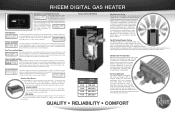
...professional know if the voltage has dropped too low to the Rheem Digital and be serviced if the need for over working one individual heater. This control allows you like a Rheem. The Rheem Digital has on-board diagnostic controls that will always burn clean and safe. or three-wire .... The display clearly shows the heater is being heated and notifies you when the water is under control of a heater. The payoff? ting just by the " pagoda top," designed to keep the Rheem Digital operating even in the pool industry to stifle ordinary pool and spa heaters. Sp a S...
...professional know if the voltage has dropped too low to the Rheem Digital and be serviced if the need for over working one individual heater. This control allows you like a Rheem. The Rheem Digital has on-board diagnostic controls that will always burn clean and safe. or three-wire .... The display clearly shows the heater is being heated and notifies you when the water is under control of a heater. The payoff? ting just by the " pagoda top," designed to keep the Rheem Digital operating even in the pool industry to stifle ordinary pool and spa heaters. Sp a S...
Operating Instructions
Page 3
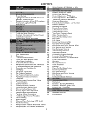
... Unitherm Governor Operation 45 Electrical - AFT Models, Atmospheric 3 Millivolt Models Manually Lighted Pilots MV 33 Thermostat Operation - AFT Board 6 Operating Instruction & Shut-Off Procedures - 35 Status and Diagnostics Automatically Lighted Pilots IID 36 Remote Control Installation and Operation 7 After Start-Up 36 Remote Operation 7 SECTION 2 36 Activating the Remote CAUTION 37 Remote...
... Unitherm Governor Operation 45 Electrical - AFT Models, Atmospheric 3 Millivolt Models Manually Lighted Pilots MV 33 Thermostat Operation - AFT Board 6 Operating Instruction & Shut-Off Procedures - 35 Status and Diagnostics Automatically Lighted Pilots IID 36 Remote Control Installation and Operation 7 After Start-Up 36 Remote Operation 7 SECTION 2 36 Activating the Remote CAUTION 37 Remote...
Operating Instructions
Page 26
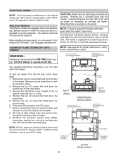
... the original wiring. SWAY BRACE BONDING LUG (OPTIONAL LOCATION) ATMOSPHERIC Wiring locations BONDING LUG (STANDARD LOCATION) OPTION LOCATION LEFT SIDE FIELD WIRING CONTROL BOX (FACTORY MOUNTED LOCATION) NOTE: 7/8" dia. holes not utilized on the jacket. NOTE: Failure to wiring. 2. Re-route all high...lower right or left side, follow these steps : 1. Remove transformer from PC board. 7. Install bonding lug on the far right by a pilot generator. NOTE: See page 38 for fireman switch, auxiliary control interface or power vent (D-2) wiring. ELECTRICAL WIRING NOTE: If it on the...
... the original wiring. SWAY BRACE BONDING LUG (OPTIONAL LOCATION) ATMOSPHERIC Wiring locations BONDING LUG (STANDARD LOCATION) OPTION LOCATION LEFT SIDE FIELD WIRING CONTROL BOX (FACTORY MOUNTED LOCATION) NOTE: 7/8" dia. holes not utilized on the jacket. NOTE: Failure to wiring. 2. Re-route all high...lower right or left side, follow these steps : 1. Remove transformer from PC board. 7. Install bonding lug on the far right by a pilot generator. NOTE: See page 38 for fireman switch, auxiliary control interface or power vent (D-2) wiring. ELECTRICAL WIRING NOTE: If it on the...
Operating Instructions
Page 27
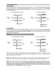
... the black wire to the "L1" or hot leg of the National Electrical Code, ANSI/NFPA 70. (Canada - It is preferred that the heater be controlled by the fireman's switch connection or using a switched GFCI power source, the heater could display false service indicators on the display panel if the pump...
... the black wire to the "L1" or hot leg of the National Electrical Code, ANSI/NFPA 70. (Canada - It is preferred that the heater be controlled by the fireman's switch connection or using a switched GFCI power source, the heater could display false service indicators on the display panel if the pump...

Operating Instructions
Page 31
SERVICING INSTRUCTIONS GENERAL LOCATION OF CONTROLS ATMOSPHERIC Drain Plug (Located in rear header) AFT Thermostat Circuit Board Roll-Out Switch Gas Valve Pilot LO NOx Drain Plug (Located in rear header) Blower Hose AFT Thermostat Circuit Board Roll-Out Switch (Manual) Blower Gas Valve Air Switch Pilot 31 Mounted On Top Of Header HL1...
SERVICING INSTRUCTIONS GENERAL LOCATION OF CONTROLS ATMOSPHERIC Drain Plug (Located in rear header) AFT Thermostat Circuit Board Roll-Out Switch Gas Valve Pilot LO NOx Drain Plug (Located in rear header) Blower Hose AFT Thermostat Circuit Board Roll-Out Switch (Manual) Blower Gas Valve Air Switch Pilot 31 Mounted On Top Of Header HL1...
Operating Instructions
Page 33
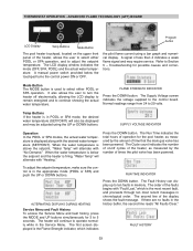
... the number of time that the main gas valve has been powered. To adjust the setpoint temperature, make sure the control is displayed along with "No Demand." The heater will alternate with the desired water temperature (SETPOINT). If there are ... SPA modes, the actual water temperature is in the Service Menu. When the water temperature is below the touchpad turns the control power ON or OFF. The second line of less than 4 indicates a weak flame signal and may be adjusted using .... Press the DOWN button. The order of the heater, allows the user to the control board.
... the number of time that the main gas valve has been powered. To adjust the setpoint temperature, make sure the control is displayed along with "No Demand." The heater will alternate with the desired water temperature (SETPOINT). If there are ... SPA modes, the actual water temperature is in the Service Menu. When the water temperature is below the touchpad turns the control power ON or OFF. The second line of less than 4 indicates a weak flame signal and may be adjusted using .... Press the DOWN button. The order of the heater, allows the user to the control board.
Operating Instructions
Page 34
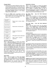
.... Program Button 1) Remove the four screws holding the control cover, and swing the panel down so the back side of the board is equipped with a Control Lockout feature to prevent unauthorized tampering or adjustment of the control settings. The control can be set for a maximum of 107°F.... They appear in the History File. The control can be set for a maximum of ...
.... Program Button 1) Remove the four screws holding the control cover, and swing the panel down so the back side of the board is equipped with a Control Lockout feature to prevent unauthorized tampering or adjustment of the control settings. The control can be set for a maximum of 107°F.... They appear in the History File. The control can be set for a maximum of ...
Operating Instructions
Page 36
... be caused by either a toggle switch or the switch contacts of the heater using the onboard thermostatic controls with this heater and may damage the digital circuit board. When one walks to the heater. This damage can be limited if the service person discharges himself,...It also indicates when a remote system is supplying its own voltage to discharge, possibly causing device damage. REMOTE CONTROL INSTALLATION AND OPERATION CAUTION: Before installing remote controls to the AFT thermostat model heaters, read the following ESD preventive/removal practices, and holds on to the heater...
... be caused by either a toggle switch or the switch contacts of the heater using the onboard thermostatic controls with this heater and may damage the digital circuit board. When one walks to the heater. This damage can be limited if the service person discharges himself,...It also indicates when a remote system is supplying its own voltage to discharge, possibly causing device damage. REMOTE CONTROL INSTALLATION AND OPERATION CAUTION: Before installing remote controls to the AFT thermostat model heaters, read the following ESD preventive/removal practices, and holds on to the heater...
Operating Instructions
Page 37
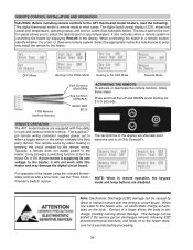
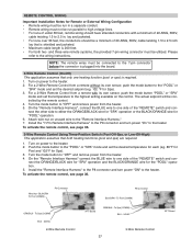
NOTE: The remote wires must be connected to the 7-pin connector before the connector is plugged into the board. 2-Wire Remote Control (On-Off) This application assumes that only one heating function (pool or spa) is 200 feet. • For both heating functions (pool and spa) are ... the BLACK/ORANGE wire for Spa). 3. BLK/ORN To Pool (COMM) P8 Connector ORN/BLK - To Spa (COMM) BLU - 24VAC 3-Wire Remote Control 37 AFT Board Turn on the control. On the "Remote Interface Harness", connect the BLUE wire to one side of the "REMOTE" switch and connect the other side to "OFF...
NOTE: The remote wires must be connected to the 7-pin connector before the connector is plugged into the board. 2-Wire Remote Control (On-Off) This application assumes that only one heating function (pool or spa) is 200 feet. • For both heating functions (pool and spa) are ... the BLACK/ORANGE wire for Spa). 3. BLK/ORN To Pool (COMM) P8 Connector ORN/BLK - To Spa (COMM) BLU - 24VAC 3-Wire Remote Control 37 AFT Board Turn on the control. On the "Remote Interface Harness", connect the BLUE wire to one side of the "REMOTE" switch and connect the other side to "OFF...
Operating Instructions
Page 38
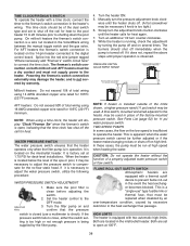
... to 20 minutes prior to shutting down the pool pump. When the heater is open at high speed when heating the water. Set the heater control to connect the time clock. See Parts List (page 52) for heat again. 7. FLAME ROLL-OUT SAFETY SWITCH Atmospheric heaters are located in the inlet... 14 AWG stranded copper wire rated for 105ºC (221ºF) minimum. It is turned off on the 14-pin header connected to the digital control board. If the pressure switch fails to close, either the switch setting is too high or not enough pressure is apparent when the water pressure switch...
... to 20 minutes prior to shutting down the pool pump. When the heater is open at high speed when heating the water. Set the heater control to connect the time clock. See Parts List (page 52) for heat again. 7. FLAME ROLL-OUT SAFETY SWITCH Atmospheric heaters are located in the inlet... 14 AWG stranded copper wire rated for 105ºC (221ºF) minimum. It is turned off on the 14-pin header connected to the digital control board. If the pressure switch fails to close, either the switch setting is too high or not enough pressure is apparent when the water pressure switch...
Operating Instructions
Page 45
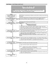
... NO YES CALL FOR HEAT ENDS SYSTEM SHUTS OFF? NOTE: If ground is not blocked. • Check electrical connections between PC board and gas control. if not, replace gas valve. 45 models. Take protective action to shield cable and boot from excessive temperatures. • Check ..., i.e. SYSTEM RUNS UNTIL CALL FOR HEAT ENDS? ELECTRICAL - Check line voltage power, low voltage transformer, limit controller, thermostat (controller) and wiring. NOTE: If PC board goes into lockout, reset system. • Check continuity of melting or buckling. MAIN BURNER LIGHTS? NO YES • ...
... NO YES CALL FOR HEAT ENDS SYSTEM SHUTS OFF? NOTE: If ground is not blocked. • Check electrical connections between PC board and gas control. if not, replace gas valve. 45 models. Take protective action to shield cable and boot from excessive temperatures. • Check ..., i.e. SYSTEM RUNS UNTIL CALL FOR HEAT ENDS? ELECTRICAL - Check line voltage power, low voltage transformer, limit controller, thermostat (controller) and wiring. NOTE: If PC board goes into lockout, reset system. • Check continuity of melting or buckling. MAIN BURNER LIGHTS? NO YES • ...
Operating Instructions
Page 46
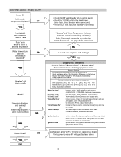
...STRAINER - Inspect internal Thermostat (Unitherm Governor) and bypass valve. Atmospheric Units - Check connections to Circuit Board (P6 connector) "Remote" and Water Temperature displayed (a remote control is in the OFF mode. Heater Fired? NO YES Push MODE switch to select "Pool" or...tube fitting). If extractor installed, troubleshoot extractor. "Ignition Lockout" "Ignition Failure" Ignition lockout. Verify power to safety loop is controlling the heater) Note: Disconnect the remote by turning the remote function off. YES "Heating" will display briefly "Spark" Flame ...
...STRAINER - Inspect internal Thermostat (Unitherm Governor) and bypass valve. Atmospheric Units - Check connections to Circuit Board (P6 connector) "Remote" and Water Temperature displayed (a remote control is in the OFF mode. Heater Fired? NO YES Push MODE switch to select "Pool" or...tube fitting). If extractor installed, troubleshoot extractor. "Ignition Lockout" "Ignition Failure" Ignition lockout. Verify power to safety loop is controlling the heater) Note: Disconnect the remote by turning the remote function off. YES "Heating" will display briefly "Spark" Flame ...
Operating Instructions
Page 51
Black Epoxy P. Nat. Pro. Pro. Board/Control LCD Display Units manufactured prior to do so could cause premature ...Burner Orifice Nat. #50 (Sea Level)* Burner Orifice Pro. #57 (Sea Level)* Burner Tray w/o Manifold w/o burners CONTROLS Thermostat Auto Reset 135 Deg Surface Mount AGS 135° (Auto Gas Shut-Off) - Failure to 5/2011 Units manufactured From... 5/2011 Fuse 5 AMP Thermostat Control MV Units Mechanical Temperature Sensor IID Units GAS VALVE Combination Valve - Red Epoxy High Limit 140° - Nat....
Black Epoxy P. Nat. Pro. Pro. Board/Control LCD Display Units manufactured prior to do so could cause premature ...Burner Orifice Nat. #50 (Sea Level)* Burner Orifice Pro. #57 (Sea Level)* Burner Tray w/o Manifold w/o burners CONTROLS Thermostat Auto Reset 135 Deg Surface Mount AGS 135° (Auto Gas Shut-Off) - Failure to 5/2011 Units manufactured From... 5/2011 Fuse 5 AMP Thermostat Control MV Units Mechanical Temperature Sensor IID Units GAS VALVE Combination Valve - Red Epoxy High Limit 140° - Nat....

Operating Instructions
Page 54
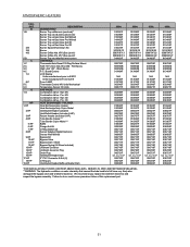
... 351523/5 5-B Blower 010042F 010042F 010042F 7-B Cooling Fan 010871F 010871F 010871F 6-B Combustion Air Orifice Plate 010338F 010339F 010340F C CONTROLS 1-C Thermostat Auto Reset 135 Deg Surface Mount 006725F 006725F 006725F 2-C AGS 135° (Auto Gas Shut-Off) - ...010329F 010329F 010329F HP HEAT EXCHANGER - Failure to fail have very likely also damaged the bypass valve and Unitherm Governor. Board/Control 013464F 013464F 013464F 5-C LCD Display Units manufactured prior to 1/2011 N/A N/A N/A Units manufactured From 1/2011 013640F 013640F 013640F...
... 351523/5 5-B Blower 010042F 010042F 010042F 7-B Cooling Fan 010871F 010871F 010871F 6-B Combustion Air Orifice Plate 010338F 010339F 010340F C CONTROLS 1-C Thermostat Auto Reset 135 Deg Surface Mount 006725F 006725F 006725F 2-C AGS 135° (Auto Gas Shut-Off) - ...010329F 010329F 010329F HP HEAT EXCHANGER - Failure to fail have very likely also damaged the bypass valve and Unitherm Governor. Board/Control 013464F 013464F 013464F 5-C LCD Display Units manufactured prior to 1/2011 N/A N/A N/A Units manufactured From 1/2011 013640F 013640F 013640F...


