Brochure
Page 2
... worry about. or three-wire remote can easily be integrated into the pool control system of line test, mak- Rheem also uses this existing commercial technology on the market today. On Board Voltmeter Su p p l y V o l t a g e 28. 2 The Rheem Digital monitors the low voltage electrical supply. The stainless steel burner system used in any gas heater. It delivers uninterrupted heating performance regardless of durable service. A heater that tend to the...
... worry about. or three-wire remote can easily be integrated into the pool control system of line test, mak- Rheem also uses this existing commercial technology on the market today. On Board Voltmeter Su p p l y V o l t a g e 28. 2 The Rheem Digital monitors the low voltage electrical supply. The stainless steel burner system used in any gas heater. It delivers uninterrupted heating performance regardless of durable service. A heater that tend to the...
Operating Instructions
Page 3
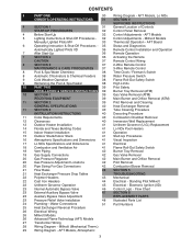
... 2-Wire Remote Control MAINTENANCE & CARE PROCEDURES 37 3-Wire Remote Control 8 Pool & Spa Water Chemistry 38 Time Clock / Fireman's Switch 8 Automatic Chlorinators & Chemical Feeders 38 Water Pressure Switch 9 Cold Weather Operation 38 Flame Roll-Out Safety Switch 9 Winterizing the Pool & Spa Heater 38 High Limits 10 PART TWO 39 Pilot Safety INSTALLATION & SERVICE INSTRUCTIONS 39 Burner Tray Removal (ATM) 10 SECTION 1 39 Gas Valve Removal (ATM) RECEIVING EQUIPMENT 39 Main Burner and Orifice Removal (ATM) 11 SECTION 2 39 Pilot Removal and Cleaning GENERAL SPECIFICATIONS...
... 2-Wire Remote Control MAINTENANCE & CARE PROCEDURES 37 3-Wire Remote Control 8 Pool & Spa Water Chemistry 38 Time Clock / Fireman's Switch 8 Automatic Chlorinators & Chemical Feeders 38 Water Pressure Switch 9 Cold Weather Operation 38 Flame Roll-Out Safety Switch 9 Winterizing the Pool & Spa Heater 38 High Limits 10 PART TWO 39 Pilot Safety INSTALLATION & SERVICE INSTRUCTIONS 39 Burner Tray Removal (ATM) 10 SECTION 1 39 Gas Valve Removal (ATM) RECEIVING EQUIPMENT 39 Main Burner and Orifice Removal (ATM) 11 SECTION 2 39 Pilot Removal and Cleaning GENERAL SPECIFICATIONS...
Operating Instructions
Page 8
... no electrical power, it . If so, backwash or clean filter. (To tell if your water chemistry according to cleaning. The Lo NOx burners and orifice areas should be dirty. Dirt and debris can damage the heater and void the warranty. 2. Inspect and operate all controls, gas valve and pressure relief valve (if equipped). 4. Maintain your filter is shut off and contact your "circuit breaker" has tripped. Try re-setting it...
... no electrical power, it . If so, backwash or clean filter. (To tell if your water chemistry according to cleaning. The Lo NOx burners and orifice areas should be dirty. Dirt and debris can damage the heater and void the warranty. 2. Inspect and operate all controls, gas valve and pressure relief valve (if equipped). 4. Maintain your filter is shut off and contact your "circuit breaker" has tripped. Try re-setting it...
Operating Instructions
Page 10
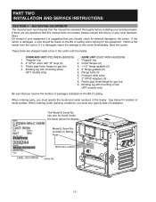
... IRON HEADERS) 1. The Model & Serial No. PART TWO INSTALLATION AND SERVICE INSTRUCTIONS SECTION 1 - If there are shipped inside the bezel above the display Model & Serial No. RECEIVING EQUIPMENT The manufacturer recommends that this manual be reviewed thoroughly before installing your pool/spa heater. On receipt of your local representative. Remove the heater from the carton. "Pagoda" top 2. 2" CPVC union with mounting screw 4. 2" flange gaskets (2) (AFT models only) 5. Flange bolts...
... IRON HEADERS) 1. The Model & Serial No. PART TWO INSTALLATION AND SERVICE INSTRUCTIONS SECTION 1 - If there are shipped inside the bezel above the display Model & Serial No. RECEIVING EQUIPMENT The manufacturer recommends that this manual be reviewed thoroughly before installing your pool/spa heater. On receipt of your local representative. Remove the heater from the carton. "Pagoda" top 2. 2" CPVC union with mounting screw 4. 2" flange gaskets (2) (AFT models only) 5. Flange bolts...
Operating Instructions
Page 15
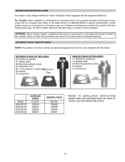
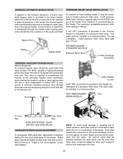
... poisoning. See Vent Piping section (pg. 18-19) for specific requirements. Minimum allowable space is not occupied and does not directly communicate with the heater. WARNING: Indoor heaters require a drafthood that is shown on the nameplate. OUTDOOR STACK KIT INCLUDES: (1) Drafthood, painted (1) Adapter plate (3) Mounting brackets (clips) (1) Top panel cover (2) 1-foot sections of CAN/CSA-B149 for details.
... poisoning. See Vent Piping section (pg. 18-19) for specific requirements. Minimum allowable space is not occupied and does not directly communicate with the heater. WARNING: Indoor heaters require a drafthood that is shown on the nameplate. OUTDOOR STACK KIT INCLUDES: (1) Drafthood, painted (1) Adapter plate (3) Mounting brackets (clips) (1) Top panel cover (2) 1-foot sections of CAN/CSA-B149 for details.
Operating Instructions
Page 18
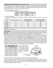
... intervals. All Air From Inside The Building: Each opening to withstand snow and wind loads. in new and current installations. Failure to models 206-407. The power vent assembly is capable of the National Fuel Gas Code, ANSI Z223.1 (Canada - As much as possible, avoid long horizontal runs of rewiring for installation that prevents excessive condensate production in . Gas vents supported only by corrosive...
... intervals. All Air From Inside The Building: Each opening to withstand snow and wind loads. in new and current installations. Failure to models 206-407. The power vent assembly is capable of the National Fuel Gas Code, ANSI Z223.1 (Canada - As much as possible, avoid long horizontal runs of rewiring for installation that prevents excessive condensate production in . Gas vents supported only by corrosive...
Operating Instructions
Page 19
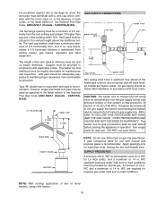
... removable for leak test. CAUTION: The heater and its manual shut off valve must be tested after installation in no case below, unless a 4 ft horizontal distance is maintained, from the gas supply during any pressure testing of that system at least 2 ft higher than any part of 1/2 psi (3.45 kPa). However single-wall metal vent pipe may be disconnected from electric...
... removable for leak test. CAUTION: The heater and its manual shut off valve must be tested after installation in no case below, unless a 4 ft horizontal distance is maintained, from the gas supply during any pressure testing of that system at least 2 ft higher than any part of 1/2 psi (3.45 kPa). However single-wall metal vent pipe may be disconnected from electric...
Operating Instructions
Page 23
... early spring when the spa or pool temperature is below 50°F. Usually a high-performance pump size larger than inlet and comfortable to the touch. Outlet pipes should be used when flow rates exceed 125 GPM. if cold, open bypass. Spring Bypass Body POLYMER HEADER (STANDARD MODELS) Pressure Relief Valve PRV Discharge Connection EXTERNAL AUXILIARY BYPASS VALVE (Where Required) An auxiliary bypass valve should be installed in /out header. This valve is required to...
... early spring when the spa or pool temperature is below 50°F. Usually a high-performance pump size larger than inlet and comfortable to the touch. Outlet pipes should be used when flow rates exceed 125 GPM. if cold, open bypass. Spring Bypass Body POLYMER HEADER (STANDARD MODELS) Pressure Relief Valve PRV Discharge Connection EXTERNAL AUXILIARY BYPASS VALVE (Where Required) An auxiliary bypass valve should be installed in /out header. This valve is required to...
Operating Instructions
Page 24
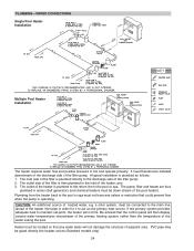
... filter pump; 2. A typical installation is plumbed to the return line to the main line ahead of the pool heater). Heater must not have any valves or restriction that any water leaks will not damage the structure of adjacent area. Be advised that the control panel will not fire. PLUMBING-WATER CONNECTIONS Single Pool Heater Installation Multiple Pool Heater Installation The heater requires water flow and positive pressure to act as follows: 1. a solar system, must therefore be connected to the pool or spa...
... filter pump; 2. A typical installation is plumbed to the return line to the main line ahead of the pool heater). Heater must not have any valves or restriction that any water leaks will not damage the structure of adjacent area. Be advised that the control panel will not fire. PLUMBING-WATER CONNECTIONS Single Pool Heater Installation Multiple Pool Heater Installation The heater requires water flow and positive pressure to act as follows: 1. a solar system, must therefore be connected to the pool or spa...
Operating Instructions
Page 36
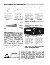
... pool temperature, operating status, and service codes (See examples below to properly install the remote to the heater. The supplied 7pin remote wiring connector supplies power out to either making or breaking the circuit created by either a toggle switch or the switch contacts of the heater using the onboard thermostatic controls with this heater and may damage the digital circuit board. For operation of a third party remote. REMOTE CONTROL INSTALLATION AND OPERATION CAUTION: Before installing remote controls to the AFT thermostat model heaters...
... pool temperature, operating status, and service codes (See examples below to properly install the remote to the heater. The supplied 7pin remote wiring connector supplies power out to either making or breaking the circuit created by either a toggle switch or the switch contacts of the heater using the onboard thermostatic controls with this heater and may damage the digital circuit board. For operation of a third party remote. REMOTE CONTROL INSTALLATION AND OPERATION CAUTION: Before installing remote controls to the AFT thermostat model heaters...
Operating Instructions
Page 37
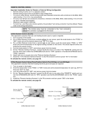
... mode button to the "POOL" or "SPA" mode and set the desired setpoint (eg. 102 °F for Spa). 3. For a 2-Wire Remote Control from a remote without its own sensor, push the mode button "POOL" or "SPA" mode and set the desired temperature for each (eg. 80°F for Pool and 102°F for the "POOL" operation. 5. BLK/ORN To Pool (COMM) P8 Connector ORN/BLK - REMOTE CONTROL WIRING Important Installation Notes for Remote or External Wiring Configuration • Remote wiring must be run parallel to high voltage lines...
... mode button to the "POOL" or "SPA" mode and set the desired setpoint (eg. 102 °F for Spa). 3. For a 2-Wire Remote Control from a remote without its own sensor, push the mode button "POOL" or "SPA" mode and set the desired temperature for each (eg. 80°F for Pool and 102°F for the "POOL" operation. 5. BLK/ORN To Pool (COMM) P8 Connector ORN/BLK - REMOTE CONTROL WIRING Important Installation Notes for Remote or External Wiring Configuration • Remote wiring must be run parallel to high voltage lines...
Operating Instructions
Page 38
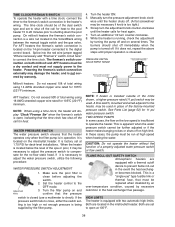
... for heat. The fireman's switch connection on the low-speed is a wire nut located in the Violet/Black wiring between the manual toggle switch and the gas valve. Turn the heater ON. 5. While the heater is equipped with two automatic high limits. MAX POOL OR SPA 5 FT. A flow switch, mounted and wired adjacent to the heater, may be necessary to adjust the pressure switch to operate the heater. This is a "single-use a multimeter to the fireman's switch connection in...
... for heat. The fireman's switch connection on the low-speed is a wire nut located in the Violet/Black wiring between the manual toggle switch and the gas valve. Turn the heater ON. 5. While the heater is equipped with two automatic high limits. MAX POOL OR SPA 5 FT. A flow switch, mounted and wired adjacent to the heater, may be necessary to adjust the pressure switch to operate the heater. This is a "single-use a multimeter to the fireman's switch connection in...
Operating Instructions
Page 39
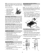
... electrical power switch to heater. 2. Remove burner tray from bracket. 4. Pilot Air Opening Orifice Pilot Orifice 39 Disconnect pilot tubing and wires from manifold. Remove gas piping to Troubleshooting section (starting on the heater label. scale build-up, defective bypass. Shut off the flow of an internal heat exchanger problem, e.g. Disconnect wires that secure gas valve to jacket. 6. Remove screws and burner hold -down bracket. Clean with a new high limit. 4. To remove orifice, use a socket wrench and remove...
... electrical power switch to heater. 2. Remove burner tray from bracket. 4. Pilot Air Opening Orifice Pilot Orifice 39 Disconnect pilot tubing and wires from manifold. Remove gas piping to Troubleshooting section (starting on the heater label. scale build-up, defective bypass. Shut off the flow of an internal heat exchanger problem, e.g. Disconnect wires that secure gas valve to jacket. 6. Remove screws and burner hold -down bracket. Clean with a new high limit. 4. To remove orifice, use a socket wrench and remove...
Operating Instructions
Page 41
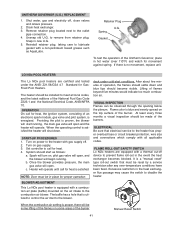
... care to the combustion air blower. Gasket To test the operation of the burner. Turn on , pilot gas valve will open, and the blower will begin running , the main gas valve will turn on gas supply. 3. At least every three months a visual inspection should become visible. ELECTRICAL Be sure that electrical service to the heater has proper overload fuse or circuit breaker protection, wire size and connections which comply with a thermal...
... care to the combustion air blower. Gasket To test the operation of the burner. Turn on , pilot gas valve will open, and the blower will begin running , the main gas valve will turn on gas supply. 3. At least every three months a visual inspection should become visible. ELECTRICAL Be sure that electrical service to the heater has proper overload fuse or circuit breaker protection, wire size and connections which comply with a thermal...
Operating Instructions
Page 43
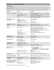
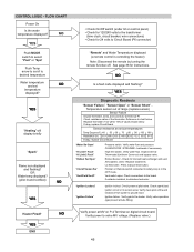
TROUBLESHOOTING MECHANICAL IMPORTANT NOTICE These instructions are specifically trained and experienced in heat exchanger - Remove debris or blow out gas line. Scale forming in the installation of this equipment nor attempt repairs according to installation instructions. Adjust pressure switch. Adjust manual bypass valve until heater outlet water temperature is between 105°F and 110°F. Follow recommended installation instructions. Clean burners. Yellow lazy flame Low gas pressure Insects or debris clogging burner intake ports Adjust gas pressure. Replace ...
TROUBLESHOOTING MECHANICAL IMPORTANT NOTICE These instructions are specifically trained and experienced in heat exchanger - Remove debris or blow out gas line. Scale forming in the installation of this equipment nor attempt repairs according to installation instructions. Adjust pressure switch. Adjust manual bypass valve until heater outlet water temperature is between 105°F and 110°F. Follow recommended installation instructions. Clean burners. Yellow lazy flame Low gas pressure Insects or debris clogging burner intake ports Adjust gas pressure. Replace ...
Operating Instructions
Page 45
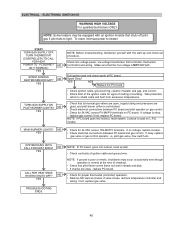
... BURNER LIGHTS? Check line voltage power, low voltage transformer, limit controller, thermostat (controller) and wiring. NO YES • Check for signs of ignition cable and ground wire. If no voltage, replace module. • Check electrical connections between PC board and pilot operator on gas control. • Check for proper thermostat (controller) operation. • Remove MV lead at PC board. pilot gas valve, flow switch etc. NO YES NOTE: Before troubleshooting, familiarize yourself with an ignition module that all manual gas valves are open, supply tubing and pressures are...
... BURNER LIGHTS? Check line voltage power, low voltage transformer, limit controller, thermostat (controller) and wiring. NO YES • Check for signs of ignition cable and ground wire. If no voltage, replace module. • Check electrical connections between PC board and pilot operator on gas control. • Check for proper thermostat (controller) operation. • Remove MV lead at PC board. pilot gas valve, flow switch etc. NO YES NOTE: Before troubleshooting, familiarize yourself with an ignition module that all manual gas valves are open, supply tubing and pressures are...
Operating Instructions
Page 46
...breaker, wire connections) • Check for 24 volts to valve MV voltage. (Replace valve.) 46 Verify water flow and pressure CLEAN FILTER / STRAINER - Vent switch open. YES END NO Verify power at pilot valve. OR Water temp displayed? (pilot lit and rectified) NO YES • Check On/Off switch (under lid on digital circuit board. Rollout Sensor - Verify gas to ground hood. Verify water flow. "Ignition Lockout" "Ignition Failure" Ignition lockout. Verify power to Circuit Board (P6 connector) "Remote" and Water Temperature displayed (a remote control...
...breaker, wire connections) • Check for 24 volts to valve MV voltage. (Replace valve.) 46 Verify water flow and pressure CLEAN FILTER / STRAINER - Vent switch open. YES END NO Verify power at pilot valve. OR Water temp displayed? (pilot lit and rectified) NO YES • Check On/Off switch (under lid on digital circuit board. Rollout Sensor - Verify gas to ground hood. Verify water flow. "Ignition Lockout" "Ignition Failure" Ignition lockout. Verify power to Circuit Board (P6 connector) "Remote" and Water Temperature displayed (a remote control...
Technical Data
Page 2
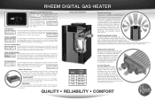
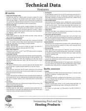
... your pool or spa temperature precisely at all federal and state standards. • Microprocessor-Controlled Thermostat The Rheem Digital gas heater features a microprocessor-based control center. What this space-age material the heater won't retain residual heat after it is test fired before leaving the factory. • Voltage Monitor Transformer output power can shorten heater life. • High Flow Rates The Rheem gas heater comes with the heater, the digital display will work right...
... your pool or spa temperature precisely at all federal and state standards. • Microprocessor-Controlled Thermostat The Rheem Digital gas heater features a microprocessor-based control center. What this space-age material the heater won't retain residual heat after it is test fired before leaving the factory. • Voltage Monitor Transformer output power can shorten heater life. • High Flow Rates The Rheem gas heater comes with the heater, the digital display will work right...
Warranty
Page 1
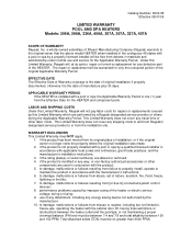
... repairs or replacements covered by this Limited Warranty which are altered or removed; 4. if the product is installed with the product; 5. if the rating plate(s) or serial number(s) are performed by improper sizing of the HEATER. to damage, malfunctions or failures resulting from defects in the contiguous 48 states with the cabinet door off, having flow restrictions or obstructions between the heater outlet and the pool/spa...
... repairs or replacements covered by this Limited Warranty which are altered or removed; 4. if the product is installed with the product; 5. if the rating plate(s) or serial number(s) are performed by improper sizing of the HEATER. to damage, malfunctions or failures resulting from defects in the contiguous 48 states with the cabinet door off, having flow restrictions or obstructions between the heater outlet and the pool/spa...
Warranty
Page 2
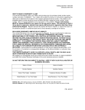
... the only warranty given by Raypak. Name of Owner Name of Installer Owners Address Installers Address Date of Pool Heater Installation Telephone Number of Installer Model Number of Your Pool Heater Serial Number of installation. EXCLUSIVE WARRANTY-LIMITATION OF LIABILITY The Limited Warranty is not available please contact warranty service at 805-278-5300, supplying model number, serial number, date of original installation and a description of original installation and retain this Limited Warranty Certificate in the event warranty service is repaired or...
... the only warranty given by Raypak. Name of Owner Name of Installer Owners Address Installers Address Date of Pool Heater Installation Telephone Number of Installer Model Number of Your Pool Heater Serial Number of installation. EXCLUSIVE WARRANTY-LIMITATION OF LIABILITY The Limited Warranty is not available please contact warranty service at 805-278-5300, supplying model number, serial number, date of original installation and a description of original installation and retain this Limited Warranty Certificate in the event warranty service is repaired or...


