

English Manual
Page 2
...OF CONTENTS WARNING DECAL PLACEMENT 2 IMPORTANT PRECAUTIONS 3 BEFORE YOU BEGIN 7 PART IDENTIFICATION CHART 8 ASSEMBLY 9 OPERATION AND ADJUSTMENT 16 HOW TO FOLD AND MOVE THE TREADMILL 23 TROUBLESHOOTING 24 EXERCISE GUIDELINES 26 PART LIST 27 EXPLODED DRAWING 28 ORDERING REPLACEMENT PARTS Back ...Cover LIMITED WARRANTY Back Cover WARNING DECAL PLACEMENT This drawing shows the locations of ICON IP, Inc. 2 Note: The decals may not be shown at actual size. PROFORM...
...OF CONTENTS WARNING DECAL PLACEMENT 2 IMPORTANT PRECAUTIONS 3 BEFORE YOU BEGIN 7 PART IDENTIFICATION CHART 8 ASSEMBLY 9 OPERATION AND ADJUSTMENT 16 HOW TO FOLD AND MOVE THE TREADMILL 23 TROUBLESHOOTING 24 EXERCISE GUIDELINES 26 PART LIST 27 EXPLODED DRAWING 28 ORDERING REPLACEMENT PARTS Back ...Cover LIMITED WARRANTY Back Cover WARNING DECAL PLACEMENT This drawing shows the locations of ICON IP, Inc. 2 Note: The decals may not be shown at actual size. PROFORM...

English Manual
Page 4
...treadmill unattended while it is properly assembled. (See ASSEMBLY on page 9 and HOW TO FOLD AND MOVE THE TREADMILL on page 7 for the location of the treadmill by an authorized service representative. Do not attempt to move the treadmill. 23. vice representative only. 28. Over exercising may affect the accuracy of the treadmill...storage position. 24. Inspect and properly tighten all parts of heart rate readings. ing the treadmill, and before clean- Never insert any opening on the treadmill. 26. DANGER: 27. Do not change the incline of the power switch), and ...
...treadmill unattended while it is properly assembled. (See ASSEMBLY on page 9 and HOW TO FOLD AND MOVE THE TREADMILL on page 7 for the location of the treadmill by an authorized service representative. Do not attempt to move the treadmill. 23. vice representative only. 28. Over exercising may affect the accuracy of the treadmill...storage position. 24. Inspect and properly tighten all parts of heart rate readings. ing the treadmill, and before clean- Never insert any opening on the treadmill. 26. DANGER: 27. Do not change the incline of the power switch), and ...

English Manual
Page 8
The number following the key number is the quantity used for assembly. Extra parts may be included. 5/16" Star Washer (8)–-2 3/8" Star Washer (5)–-10 3/8" Nut (3)–-4 #8 x 3/4" Screw (6)–-12 1/4" x 1" Screw (10)–- 4 ... Bolt (12)–-2 3/8" x 2 1/2" Bolt (2)–- 2 3/8" x 3 1/2" Screw (9)–-4 3/8" x 4" Screw (4)–-6 8 The number in the hardware kit, check to identify small parts used for assembly. Note: If a part is not in parentheses below to see if it is preattached. PART IDENTIFICATION CHART Use the drawings below each drawing is the...
The number following the key number is the quantity used for assembly. Extra parts may be included. 5/16" Star Washer (8)–-2 3/8" Star Washer (5)–-10 3/8" Nut (3)–-4 #8 x 3/4" Screw (6)–-12 1/4" x 1" Screw (10)–- 4 ... Bolt (12)–-2 3/8" x 2 1/2" Bolt (2)–- 2 3/8" x 3 1/2" Screw (9)–-4 3/8" x 4" Screw (4)–-6 8 The number in the hardware kit, check to identify small parts used for assembly. Note: If a part is not in parentheses below to see if it is preattached. PART IDENTIFICATION CHART Use the drawings below each drawing is the...
English Manual
Page 9
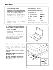
... adjustable wrench one side is an oily substance on the exterior of the treadmill. Make sure that the power cord is normal. ASSEMBLY •• Assembly requires two persons. •• Place all assembly steps. •• After shipping, there may be an oily substance on... the treadmill, wipe it off with a soft cloth and a mild, non-abrasive cleaner. •• ...
... adjustable wrench one side is an oily substance on the exterior of the treadmill. Make sure that the power cord is normal. ASSEMBLY •• Assembly requires two persons. •• Place all assembly steps. •• After shipping, there may be an oily substance on... the treadmill, wipe it off with a soft cloth and a mild, non-abrasive cleaner. •• ...
English Manual
Page 13
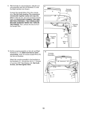
...(71) and 9 the Right Handrail (not shown). Insert the excess Upright Wire (70) into place. Start both Screws, and then tighten them. 10 Console Assembly 72 8 7 70 71 8 7 13 9. See the inset drawing. If they do not, turn one connector and try again. The connectors should slide together... easily and snap into the Left Handrail. Then, remove the wire tie from the Upright Wire. Set the console assembly on the Handrails (71, 72) with two 5/16" x 1" Screws (7) and two 5/16" Star Washers (8). IF YOU DO NOT CONNECT THE CONNECTORS ...
...(71) and 9 the Right Handrail (not shown). Insert the excess Upright Wire (70) into place. Start both Screws, and then tighten them. 10 Console Assembly 72 8 7 70 71 8 7 13 9. See the inset drawing. If they do not, turn one connector and try again. The connectors should slide together... easily and snap into the Left Handrail. Then, remove the wire tie from the Upright Wire. Set the console assembly on the Handrails (71, 72) with two 5/16" x 1" Screws (7) and two 5/16" Star Washers (8). IF YOU DO NOT CONNECT THE CONNECTORS ...

English Manual
Page 14
11. Start all of the Screws before tightening them; Orient the Left and Right Trays (45, 85) as shown, and attach each Tray with four #8 x 3/4" Screws (6). Attach the two Console Clamps (34) to overtighten the Screws. 85 6 6 45 6 6 14 be careful not to the console assembly with four #8 x 3/4" 12 Screws (6). See step 4. Tighten the six 3/8" x 4" Screws (4). 11 Console Assembly 34 6 12.
11. Start all of the Screws before tightening them; Orient the Left and Right Trays (45, 85) as shown, and attach each Tray with four #8 x 3/4" Screws (6). Attach the two Console Clamps (34) to overtighten the Screws. 85 6 6 45 6 6 14 be careful not to the console assembly with four #8 x 3/4" 12 Screws (6). See step 4. Tighten the six 3/8" x 4" Screws (4). 11 Console Assembly 34 6 12.


