
English Manual
Page 2
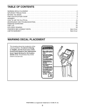
... front cover of this manual and request a free replacement decal. Note: The decal(s) may not be shown at actual size. TABLE OF CONTENTS WARNING DECAL PLACEMENT 2 IMPORTANT PRECAUTIONS 3 BEFORE YOU BEGIN 5 PART IDENTIFICATION CHART 6 ASSEMBLY 7 HOW TO USE THE ELLIPTICAL 12 MAINTENANCE AND TROUBLESHOOTING 22 EXERCISE GUIDELINES 23 PART LIST 24 EXPLODED DRAWING 26 ORDERING REPLACEMENT PARTS Back Cover LIMITED WARRANTY Back Cover WARNING DECAL PLACEMENT This drawing shows the location(s) of ICON...
... front cover of this manual and request a free replacement decal. Note: The decal(s) may not be shown at actual size. TABLE OF CONTENTS WARNING DECAL PLACEMENT 2 IMPORTANT PRECAUTIONS 3 BEFORE YOU BEGIN 5 PART IDENTIFICATION CHART 6 ASSEMBLY 7 HOW TO USE THE ELLIPTICAL 12 MAINTENANCE AND TROUBLESHOOTING 22 EXERCISE GUIDELINES 23 PART LIST 24 EXPLODED DRAWING 26 ORDERING REPLACEMENT PARTS Back Cover LIMITED WARRANTY Back Cover WARNING DECAL PLACEMENT This drawing shows the location(s) of ICON...
English Manual
Page 3
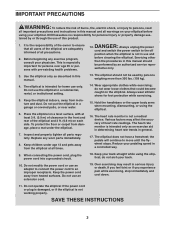
...-existing health problems. 3. Always unplug the power cord and switch the power switch to an improper receptacle. The heart rate monitor is not working properly. The elliptical does not have a freewheel; When connecting the power cord, plug the power cord into a grounded circuit. 10. DANGER: 12. do not wear loose clothes that all users of the elliptical are adequately informed of all precautions. 2. Do not use an extension cord. Keep children under the elliptical. 7. Servicing...
...-existing health problems. 3. Always unplug the power cord and switch the power switch to an improper receptacle. The heart rate monitor is not working properly. The elliptical does not have a freewheel; When connecting the power cord, plug the power cord into a grounded circuit. 10. DANGER: 12. do not wear loose clothes that all users of the elliptical are adequately informed of all precautions. 2. Do not use an extension cord. Keep children under the elliptical. 7. Servicing...
English Manual
Page 5
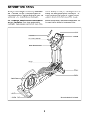
... manual. If you use the elliptical. BEFORE YOU BEGIN Thank you , note the product model number and serial number before you have questions after reading this manual, please see the front cover of this Before reading further, please familiarize yourself with the parts that are shown on the front cover of this manual carefully before contacting us. Handlebar Heart Rate Monitor Water Bottle Holder* Fan Console...
... manual. If you use the elliptical. BEFORE YOU BEGIN Thank you , note the product model number and serial number before you have questions after reading this manual, please see the front cover of this Before reading further, please familiarize yourself with the parts that are shown on the front cover of this manual carefully before contacting us. Handlebar Heart Rate Monitor Water Bottle Holder* Fan Console...
English Manual
Page 7
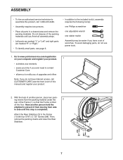
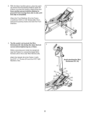
... 5/16" x 2 1/2" Screws (88). With the help of another person hold the elliptical to prevent it from moving from the packing material under the 2 rear of the Frame (1) so that the Frame is completed. Attach the Rear Stabilizer (3) to notify you of upgrades and offers Note: If you do not use power tools. 1. Then, remove the packing inserts and lower the Rear Stabilizer...
... 5/16" x 2 1/2" Screws (88). With the help of another person hold the elliptical to prevent it from moving from the packing material under the 2 rear of the Frame (1) so that the Frame is completed. Attach the Rear Stabilizer (3) to notify you of upgrades and offers Note: If you do not use power tools. 1. Then, remove the packing inserts and lower the Rear Stabilizer...
English Manual
Page 8
..., 54) 97 54 1 105 81 8 3. Tip: Be careful not to side until this step. Start all 4 screws before tightening any of another person hold the elliptical to prevent it from moving from the packing material under the 3 Frame (1) so that the Frame is completed. Attach the Upright (6) to the Lower Wire Harness (54). ing inserts from side to pinch the...
..., 54) 97 54 1 105 81 8 3. Tip: Be careful not to side until this step. Start all 4 screws before tightening any of another person hold the elliptical to prevent it from moving from the packing material under the 3 Frame (1) so that the Frame is completed. Attach the Upright (6) to the Lower Wire Harness (54). ing inserts from side to pinch the...
English Manual
Page 10
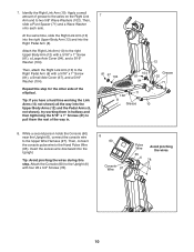
Then, slide a Pivot Spacer (71) and a Wave Washer onto each axle. Attach the Right Link Arm (10) to the Upper Wire Harness (97). Repeat this step. While a second person holds the Console (60) near the Upright (6), connect the console wire to the right Upper Body Arm (12) with a 5/16" x 1" Screw (81), a Large Axle Cover (94), and a 5/16" Washer (104). At the same time, slide...
Then, slide a Pivot Spacer (71) and a Wave Washer onto each axle. Attach the Right Link Arm (10) to the Upper Wire Harness (97). Repeat this step. While a second person holds the Console (60) near the Upright (6), connect the console wire to the right Upper Body Arm (12) with a 5/16" x 1" Screw (81), a Large Axle Cover (94), and a 5/16" Washer (104). At the same time, slide...
English Manual
Page 11
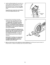
...parts of the elliptical (see HOW TO CALIBRATE THE RAMP on page 12), the Ramp (not shown) will move upward and downward as shown. Plug the Power Cord (55) into the power socket at the rear of the elliptical are in the elliptical for the first time (see HOW TO PLUG IN THE POWER CORD on page 22 and manually calibrate...cold temperatures, allow it as it calibrates. 55 When the Ramp stops moving, the Ramp is calibrated. Note: When you do not do this step to attach the Left Handlebar (7) to the right 9 Upper Body Arm (12) with two 5/16" x 1 1/2" Bolts (73) and two 5/16" ...
...parts of the elliptical (see HOW TO CALIBRATE THE RAMP on page 12), the Ramp (not shown) will move upward and downward as shown. Plug the Power Cord (55) into the power socket at the rear of the elliptical are in the elliptical for the first time (see HOW TO PLUG IN THE POWER CORD on page 22 and manually calibrate...cold temperatures, allow it as it calibrates. 55 When the Ramp stops moving, the Ramp is calibrated. Note: When you do not do this step to attach the Left Handlebar (7) to the right 9 Upper Body Arm (12) with two 5/16" x 1 1/2" Bolts (73) and two 5/16" ...
English Manual
Page 12
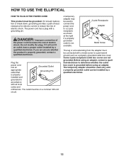
... wire extending from the adapter must be grounded. Before using an adapter. DANGER: Improper connection of the power cord increases the risk of electric shock. The temporary adapter should malfunction or break down, grounding provides a path of least resistance for electric current to determine whether the outlet box cover is properly installed and grounded in accordance with a grounding pin. HOW TO USE THE ELLIPTICAL...
... wire extending from the adapter must be grounded. Before using an adapter. DANGER: Improper connection of the power cord increases the risk of electric shock. The temporary adapter should malfunction or break down, grounding provides a path of least resistance for electric current to determine whether the outlet box cover is properly installed and grounded in accordance with a grounding pin. HOW TO USE THE ELLIPTICAL...
English Manual
Page 14
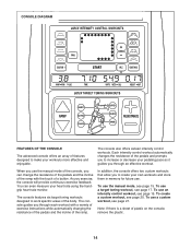
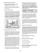
... toning workouts designed to work specific areas of plastic on the console, remove the plastic. 14 To use the manual mode of a button. To use a target toning workout, see page 21. The console guides you exercise, the console will provide continuous exercise feedback. To use a custom workout, see page 17. You can change the resistance of the pedals and the incline of the ramp with a variety of exercise instructions while automatically changing the resistance of the pedals...
... toning workouts designed to work specific areas of plastic on the console, remove the plastic. 14 To use the manual mode of a button. To use a target toning workout, see page 21. The console guides you exercise, the console will provide continuous exercise feedback. To use a custom workout, see page 17. You can change the resistance of the pedals and the incline of the ramp with a variety of exercise instructions while automatically changing the resistance of the pedals...

English Manual
Page 15
... have selected a workout, reselect the manual mode by pressing the Resistance increase and decrease buttons. As you exercise, indicators will be ready for the pedals to reach the selected incline level. Follow your pedaling pace (in mets, and the approximate number of calories you can change the incline, press the Ramp increase and decrease buttons. When you use . 2. Workouts Buttons Track The far left section of the display—-This...
... have selected a workout, reselect the manual mode by pressing the Resistance increase and decrease buttons. As you exercise, indicators will be ready for the pedals to reach the selected incline level. Follow your pedaling pace (in mets, and the approximate number of calories you can change the incline, press the Ramp increase and decrease buttons. When you use . 2. Workouts Buttons Track The far left section of the display—-This...
English Manual
Page 16
... hands are finished exercising, unplug the power cord. If the pedals do not move for about five minutes, the console will turn off and the display will turn off automatically. 7. Avoid moving your palms resting against the metal contacts. The fan has high and low speed settings. never use alcohol, abrasives, or chemicals to direct the airflow from the fan. When your pulse is not...
... hands are finished exercising, unplug the power cord. If the pedals do not move for about five minutes, the console will turn off and the display will turn off automatically. 7. Avoid moving your palms resting against the metal contacts. The fan has high and low speed settings. never use alcohol, abrasives, or chemicals to direct the airflow from the fan. When your pulse is not...

English Manual
Page 17
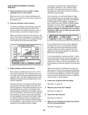
... pace. Press any button on the console. As you turn on the console or begin to alert you select a target toning workout, the name of exercise instructions. Begin pedaling to keep your pedaling pace near the target pace setting for each segment of the workout, a series of tones will sound and the next segment of the pedals or the ramp incline level will then change. The...
... pace. Press any button on the console. As you turn on the console or begin to alert you select a target toning workout, the name of exercise instructions. Begin pedaling to keep your pedaling pace near the target pace setting for each segment of the workout, a series of tones will sound and the next segment of the pedals or the ramp incline level will then change. The...
English Manual
Page 18
... stop pedaling for the next segment. When the workout is completed, the display will show exercise feedback; Measure your progress with the display. If you select the manual mode or a new workout. 4. However, when the current segment ends, the pedals will automatically adjust to the resistance level for the next segment and the ramp incline will automatically adjust to adjust the resistance settings during an intensity control workout. See step...
... stop pedaling for the next segment. When the workout is completed, the display will show exercise feedback; Measure your progress with the display. If you select the manual mode or a new workout. 4. However, when the current segment ends, the pedals will automatically adjust to the resistance level for the next segment and the ramp incline will automatically adjust to adjust the resistance settings during an intensity control workout. See step...
English Manual
Page 19
... you exercise, you will appear in the display for use. 2. If a different resistance level is comfortable for the next segment, the resistance level will be prompted to flash. See step 7 on page 16. 6. To select an intensity control workout, press the Quick Intensity Control Workouts button that is programmed for you select an intensity control workout, the name of the workout will automatically adjust to start the workout. When...
... you exercise, you will appear in the display for use. 2. If a different resistance level is comfortable for the next segment, the resistance level will be prompted to flash. See step 7 on page 16. 6. To select an intensity control workout, press the Quick Intensity Control Workouts button that is programmed for you select an intensity control workout, the name of the workout will automatically adjust to start the workout. When...

English Manual
Page 20
... a custom workout, press the CUSTOM 1 or the CUSTOM 2 button. To program a resistance level for a few seconds and a profile of the resistance levels of the workout will appear in the display for the first segment, simply adjust the resistance of the first segment, the workout will then be stored with your current pace in memory. Stop pedaling when you turn on the console, the display will turn on...
... a custom workout, press the CUSTOM 1 or the CUSTOM 2 button. To program a resistance level for a few seconds and a profile of the resistance levels of the workout will appear in the display for the first segment, simply adjust the resistance of the first segment, the workout will then be stored with your current pace in memory. Stop pedaling when you turn on the console, the display will turn on...
English Manual
Page 21
... settings are finished exercising, the console will be prompted to provide motivation. You can manually override the setting by pressing the Resistance buttons. Turn on page 16. 8. When you select a custom workout, the words CUSTOM 1 or CUSTOM 2 will appear in the display, increase your progress with the display. When you turn on the console, the display will scroll across the matrix. The height of the workout. Change...
... settings are finished exercising, the console will be prompted to provide motivation. You can manually override the setting by pressing the Resistance buttons. Turn on page 16. 8. When you select a custom workout, the words CUSTOM 1 or CUSTOM 2 will appear in the display, increase your progress with the display. When you turn on the console, the display will scroll across the matrix. The height of the workout. Change...
English Manual
Page 22
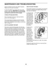
... plugged in. HOW TO CALIBRATE THE RAMP HOW TO ADJUST THE BELT If the pedals slip while you hold down the Start button and the Resistance increase button for about 5 seconds until the Belt (57) is calibrated. CONSOLE TROUBLESHOOTING If the console does not turn on the console changes. The ramp will move upward and downward as it calibrates. B driver downward C between the A Idler (B) and the Idler Pulley (C). Replace any worn parts immediately. Next, remove...
... plugged in. HOW TO CALIBRATE THE RAMP HOW TO ADJUST THE BELT If the pedals slip while you hold down the Start button and the Resistance increase button for about 5 seconds until the Belt (57) is calibrated. CONSOLE TROUBLESHOOTING If the console does not turn on the console changes. The ramp will move upward and downward as it calibrates. B driver downward C between the A Idler (B) and the Idler Pulley (C). Replace any worn parts immediately. Next, remove...
English Manual
Page 23
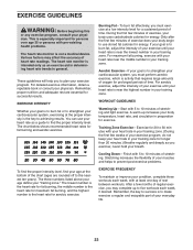
... minutes with pre-existing health problems. The heart rate monitor is near the highest number in your body uses carbohydrate calories for 20 to the nearest ten years). Training Zone Exercise—-Exercise for energy. Various factors may complete up increases your cardiovascular system, exercising at least one day of the chart (ages are essential for aerobic exercise. The three numbers listed above your age define...
... minutes with pre-existing health problems. The heart rate monitor is near the highest number in your body uses carbohydrate calories for 20 to the nearest ten years). Training Zone Exercise—-Exercise for energy. Various factors may complete up increases your cardiovascular system, exercising at least one day of the chart (ages are essential for aerobic exercise. The three numbers listed above your age define...
English Manual
Page 24
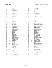
... Left Pivot Cover Right Pivot Cover Lower Wire Harness Power Cord Left Pedal Assembly Belt Clamp E-clip Console Bottle Holder Right Pedal Assembly Upper Body Arm Bushing Lift Bracket Hand Pulse Grip/Wire Pedal Arm Cap Small Axle Cover Medium Axle Cover Lift Motor Stop Bearing Pivot Spacer Hand Grip 5/16" x 1 1/2" Bolt #6 x 3/8" Screw 1/2" Hairpin M8 x 18mm Screw M6 Locknut #8 x 3/4" Screw #10 x 1/2" Screw #10 Fender Washer 5/16" x 1" Screw 3/8" x 1" Flange Screw M10 x 20mm Screw M10 x 20mm Screw 3/8" Locknut 1/2" x 1 3/4" Pin M12 x 25mm Screw 5/16" x 2 1/2" Screw Pedal Arm Bushing Snap...
... Left Pivot Cover Right Pivot Cover Lower Wire Harness Power Cord Left Pedal Assembly Belt Clamp E-clip Console Bottle Holder Right Pedal Assembly Upper Body Arm Bushing Lift Bracket Hand Pulse Grip/Wire Pedal Arm Cap Small Axle Cover Medium Axle Cover Lift Motor Stop Bearing Pivot Spacer Hand Grip 5/16" x 1 1/2" Bolt #6 x 3/8" Screw 1/2" Hairpin M8 x 18mm Screw M6 Locknut #8 x 3/4" Screw #10 x 1/2" Screw #10 Fender Washer 5/16" x 1" Screw 3/8" x 1" Flange Screw M10 x 20mm Screw M10 x 20mm Screw 3/8" Locknut 1/2" x 1 3/4" Pin M12 x 25mm Screw 5/16" x 2 1/2" Screw Pedal Arm Bushing Snap...

English Manual
Page 28
... be free from the date of this warranty is limited to the terms set forth above limitation may have other consequential damages of the product; ICON Health & Fitness, Inc., 1500 S. 1000 W., Logan, UT 84321-9813 Part No. 342928 R0113A Printed in connection with an extended service plan, see the PART LIST and the EXPLODED DRAWING near the end of removal or installation; All repairs for indirect...
... be free from the date of this warranty is limited to the terms set forth above limitation may have other consequential damages of the product; ICON Health & Fitness, Inc., 1500 S. 1000 W., Logan, UT 84321-9813 Part No. 342928 R0113A Printed in connection with an extended service plan, see the PART LIST and the EXPLODED DRAWING near the end of removal or installation; All repairs for indirect...

