

English Manual
Page 2
...Cisco in the U.S. and other countries. and are trademarks of Apple Inc., registered in the U.S. IOS is a trademark of Google Inc. PROFORM is a registered trademark of ICON Health & Fitness, Inc. IFIT is a registered trademark of ICON Health & Fitness, Inc. Android and ... WARNING DECAL PLACEMENT 2 IMPORTANT PRECAUTIONS 3 BEFORE YOU BEGIN 6 PART IDENTIFICATION CHART 7 ASSEMBLY 8 HOW TO USE THE TREADMILL 17 FCC INFORMATION 24 HOW TO FOLD AND MOVE THE TREADMILL 25 MAINTENANCE AND TROUBLESHOOTING 26 EXERCISE GUIDELINES 28 PART LIST 30 EXPLODED DRAWING 32 ORDERING ...
...Cisco in the U.S. and other countries. and are trademarks of Apple Inc., registered in the U.S. IOS is a trademark of Google Inc. PROFORM is a registered trademark of ICON Health & Fitness, Inc. IFIT is a registered trademark of ICON Health & Fitness, Inc. Android and ... WARNING DECAL PLACEMENT 2 IMPORTANT PRECAUTIONS 3 BEFORE YOU BEGIN 6 PART IDENTIFICATION CHART 7 ASSEMBLY 8 HOW TO USE THE TREADMILL 17 FCC INFORMATION 24 HOW TO FOLD AND MOVE THE TREADMILL 25 MAINTENANCE AND TROUBLESHOOTING 26 EXERCISE GUIDELINES 28 PART LIST 30 EXPLODED DRAWING 32 ORDERING ...
English Manual
Page 4
...30. Over exercising may affect the accuracy of the power switch), and unplug the power cord when the treadmill is properly assembled. (See ASSEMBLY on page 8 and HOW TO FOLD AND MOVE THE TREADMILL on page 6 for the location of heart rate readings. Keep fingers, hair, and clothing away from the... moving the treadmill, make sure that the storage latch is walking on the foot rails when starting or ...
...30. Over exercising may affect the accuracy of the power switch), and unplug the power cord when the treadmill is properly assembled. (See ASSEMBLY on page 8 and HOW TO FOLD AND MOVE THE TREADMILL on page 6 for the location of heart rate readings. Keep fingers, hair, and clothing away from the... moving the treadmill, make sure that the storage latch is walking on the foot rails when starting or ...
English Manual
Page 6
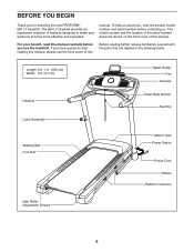
...Before reading further, please familiarize yourself with the parts that are labeled in . (185 cm) Width: 3 ft. (91 cm) Handrail Latch Assembly Tablet Holder Fan Console Heart Rate Monitor Key/Clip Walking Belt Foot Rail Motor Hood Power Switch Power Cord Wheel Platform Cushions Idler Roller Adjustment... cover of features designed to make your benefit, read this manual carefully before contacting us assist you for selecting the new PROFORM® 650 LT treadmill. Length: 6 ft. 1 in the drawing below. The 650 LT treadmill provides an impressive selection of this manual.
...Before reading further, please familiarize yourself with the parts that are labeled in . (185 cm) Width: 3 ft. (91 cm) Handrail Latch Assembly Tablet Holder Fan Console Heart Rate Monitor Key/Clip Walking Belt Foot Rail Motor Hood Power Switch Power Cord Wheel Platform Cushions Idler Roller Adjustment... cover of features designed to make your benefit, read this manual carefully before contacting us assist you for selecting the new PROFORM® 650 LT treadmill. Length: 6 ft. 1 in the drawing below. The 650 LT treadmill provides an impressive selection of this manual.

English Manual
Page 7
The number following the key number is the quantity used for assembly. Note: If a part is not in parentheses below to see whether it is preattached. Extra parts may be included. #10 Star Washer (5)-4 1/4" Star Washer (26)-6 5/... the part, from the PART LIST near the end of this manual. The number in the hardware kit, check to identify small parts used for assembly.
The number following the key number is the quantity used for assembly. Note: If a part is not in parentheses below to see whether it is preattached. Extra parts may be included. #10 Star Washer (5)-4 1/4" Star Washer (26)-6 5/... the part, from the PART LIST near the end of this manual. The number in the hardware kit, check to identify small parts used for assembly.
English Manual
Page 8
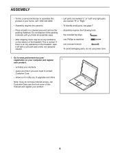
... dispose of the packing materials until you finish all parts in your product. 8 If there is normal. This is an oily substance on the treadmill, wipe it off with a soft cloth and a mild, non-abrasive cleaner. • Left parts are marked "L" or "Left" and right parts are marked "R" or "... the front cover of this product in a cleared area and remove the packing materials. Go to www.proformservice.com/ registration on the exterior of the treadmill. ASSEMBLY • To hire a service technician to notify you of upgrades and offers Note: If you do not use power tools. 1.
... dispose of the packing materials until you finish all parts in your product. 8 If there is normal. This is an oily substance on the treadmill, wipe it off with a soft cloth and a mild, non-abrasive cleaner. • Left parts are marked "L" or "Left" and right parts are marked "R" or "... the front cover of this product in a cleared area and remove the packing materials. Go to www.proformservice.com/ registration on the exterior of the treadmill. ASSEMBLY • To hire a service technician to notify you of upgrades and offers Note: If you do not use power tools. 1.

English Manual
Page 12
... Base. Identify the Left Tray (36). The connectors should slide together easily and snap into place. With the help of a second person, hold the console assembly (F) near the right Handrail (84) and the Left Handrail (not shown). Remove and save the four 1/4" x 1/2" Screws (2). See the inset drawing.
... Base. Identify the Left Tray (36). The connectors should slide together easily and snap into place. With the help of a second person, hold the console assembly (F) near the right Handrail (84) and the Left Handrail (not shown). Remove and save the four 1/4" x 1/2" Screws (2). See the inset drawing.

English Manual
Page 13
...Handrail Cover; Tighten three #8 x 1/2" Screws (1) into the Right Upright (90). do not fully tighten the Screws. Set the console assembly (F) on the right Handrail (84). Attach the console assembly (F) to the brackets on the Handrails (84) with the four 1/4" x 1/2" Screws (2) that no wires are pinched. Set the ...Screws. 10 84 81 26 2 90 F 84 26 2 11. Next, slide the Right Handrail Cover (31) forward until it slides under the console assembly (F). Identify the Right Handrail Cover (31). Make sure that you removed in the same way. 11 87 84 1 F 31 84 1 13 do not...
...Handrail Cover; Tighten three #8 x 1/2" Screws (1) into the Right Upright (90). do not fully tighten the Screws. Set the console assembly (F) on the right Handrail (84). Attach the console assembly (F) to the brackets on the Handrails (84) with the four 1/4" x 1/2" Screws (2) that no wires are pinched. Set the ...Screws. 10 84 81 26 2 90 F 84 26 2 11. Next, slide the Right Handrail Cover (31) forward until it slides under the console assembly (F). Identify the Right Handrail Cover (31). Make sure that you removed in the same way. 11 87 84 1 F 31 84 1 13 do not...

English Manual
Page 14
... the Console Ground Wire (58). Make sure that no wires are pinched. 13 F 85 G 93 1 1 58 1 14 Hold the Pulse Bar (85) near the console assembly (F). F 79 1 1 74 13. do not overtighten the Screws. start all eleven Screws, and then tighten them. Attach the Pulse Bar (85) to the Pulse Crossbar... two #8 x 1/2" Screws (1); Slide the Right and Left Handrail Grips (74, 79) over the Right and Left Handrail Covers (not 12 shown) and against the console assembly (F). 12.
... the Console Ground Wire (58). Make sure that no wires are pinched. 13 F 85 G 93 1 1 58 1 14 Hold the Pulse Bar (85) near the console assembly (F). F 79 1 1 74 13. do not overtighten the Screws. start all eleven Screws, and then tighten them. Attach the Pulse Bar (85) to the Pulse Crossbar... two #8 x 1/2" Screws (1); Slide the Right and Left Handrail Grips (74, 79) over the Right and Left Handrail Covers (not 12 shown) and against the console assembly (F). 12.

English Manual
Page 15
... 15. Firmly tighten the four 3/8" x 2 1/4" Screws (7), the two 3/8" x 1 3/4" Screws (62), 15 and the two 3/8" x 1 1/4" Screws (63). do not over- Orient the Latch Assembly (52) as shown. Attach the Latch Assembly to the Left 14 Upright (89) with two 1/4" x 4 1/2" Screws (6) and two 1/4" Star Washers (26); Next, set the Right Inner Base Cover (101...
... 15. Firmly tighten the four 3/8" x 2 1/4" Screws (7), the two 3/8" x 1 3/4" Screws (62), 15 and the two 3/8" x 1 1/4" Screws (63). do not over- Orient the Latch Assembly (52) as shown. Attach the Latch Assembly to the Left 14 Upright (89) with two 1/4" x 4 1/2" Screws (6) and two 1/4" Star Washers (26); Next, set the Right Inner Base Cover (101...

English Manual
Page 16
... to the console assembly (F) with most full-size tablets. Do not place any other electronic device or object in a secure place; Keep the included hex key in the Tablet Holder. 16 25 Start First 8 8 F 17. To protect the floor or carpet, place a mat under the treadmill. Note: Extra ...to adjust the walking belt (see page 27). the hex key is designed for use the treadmill. IMPORTANT: The Tablet Holder (25) is used to the console, keep the treadmill out of plastic on the treadmill decals, remove the plastic. 16. Note: Start the two top Machine Screws first...
... to the console assembly (F) with most full-size tablets. Do not place any other electronic device or object in a secure place; Keep the included hex key in the Tablet Holder. 16 25 Start First 8 8 F 17. To protect the floor or carpet, place a mat under the treadmill. Note: Extra ...to adjust the walking belt (see page 27). the hex key is designed for use the treadmill. IMPORTANT: The Tablet Holder (25) is used to the console, keep the treadmill out of plastic on the treadmill decals, remove the plastic. 16. Note: Start the two top Machine Screws first...

English Manual
Page 30
... 1 83 1 84 2 85 1 86 2 87 1 88 1 89 1 90 1 91 2 92 4 93 1 94 1 95 7 96 2 Description Drive Roller/Pulley Base Pad Spacer 9/32" Plastic Bushing Latch Assembly 1/4" x 1 1/4" Screw Drive Motor Motor Belt Frame Left Rear Foot Console Ground Wire Rubber Cushion Right Foot Rail Idler Roller 3/8" x 1 3/4" Screw 3/8" x 1 1/4" Screw Console Base Motor Hood...
... 1 83 1 84 2 85 1 86 2 87 1 88 1 89 1 90 1 91 2 92 4 93 1 94 1 95 7 96 2 Description Drive Roller/Pulley Base Pad Spacer 9/32" Plastic Bushing Latch Assembly 1/4" x 1 1/4" Screw Drive Motor Motor Belt Frame Left Rear Foot Console Ground Wire Rubber Cushion Right Foot Rail Idler Roller 3/8" x 1 3/4" Screw 3/8" x 1 1/4" Screw Console Base Motor Hood...


