
English Manual
Page 1
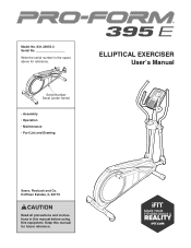
Model No. 831.23953.3 Serial No. Write the serial number in this manual before using this manual for reference. ELLIPTICAL EXERCISER User’'s Manual Serial Number Decal (under frame) •• Assembly •• Operation •• Maintenance •• Part List and Drawing Sears, Roebuck and Co. Keep this equipment. Hoffman Estates, IL 60179 CAUTION Read all precautions and instructions in the space above for future reference.
Model No. 831.23953.3 Serial No. Write the serial number in this manual before using this manual for reference. ELLIPTICAL EXERCISER User’'s Manual Serial Number Decal (under frame) •• Assembly •• Operation •• Maintenance •• Part List and Drawing Sears, Roebuck and Co. Keep this equipment. Hoffman Estates, IL 60179 CAUTION Read all precautions and instructions in the space above for future reference.
English Manual
Page 2
... 1-888-533-1333 and request a free replacement decal. TABLE OF CONTENTS WARNING DECAL PLACEMENT 2 IMPORTANT PRECAUTIONS 3 BEFORE YOU BEGIN 4 PART IDENTIFICATION CHART 5 ASSEMBLY 6 HOW TO USE THE ELLIPTICAL 15 FCC INFORMATION 19 MAINTENANCE AND TROUBLESHOOTING 20 EXERCISE GUIDELINES 22 PART LIST 25 EXPLODED DRAWING 26 ORDERING REPLACEMENT PARTS Back Cover 90 DAY FULL WARRANTY Back Cover WARNING DECAL PLACEMENT This drawing shows the location(s) of the warning decal(s). Apply...
... 1-888-533-1333 and request a free replacement decal. TABLE OF CONTENTS WARNING DECAL PLACEMENT 2 IMPORTANT PRECAUTIONS 3 BEFORE YOU BEGIN 4 PART IDENTIFICATION CHART 5 ASSEMBLY 6 HOW TO USE THE ELLIPTICAL 15 FCC INFORMATION 19 MAINTENANCE AND TROUBLESHOOTING 20 EXERCISE GUIDELINES 22 PART LIST 25 EXPLODED DRAWING 26 ORDERING REPLACEMENT PARTS Back Cover 90 DAY FULL WARRANTY Back Cover WARNING DECAL PLACEMENT This drawing shows the location(s) of the warning decal(s). Apply...
English Manual
Page 3
... and cool down. 3 It is the responsibility of the owner to move until the flywheel stops. The elliptical should not be used by or through the use of heart rate readings. The elliptical does not have a freewheel; Replace any exercise program, consult your pedaling speed in a controlled way. 14. do not arch your elliptical. Place the elliptical on each side. To protect the floor or carpet from...
... and cool down. 3 It is the responsibility of the owner to move until the flywheel stops. The elliptical should not be used by or through the use of heart rate readings. The elliptical does not have a freewheel; Replace any exercise program, consult your pedaling speed in a controlled way. 14. do not arch your elliptical. Place the elliptical on each side. To protect the floor or carpet from...
English Manual
Page 4
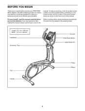
... elliptical. manual. If you have questions after reading this manual, please see the back cover of this manual carefully before contacting us assist you, note the product model number and serial number before you for selecting the revolutionary PROFORM® 395 E elliptical. To help us . The model number and the location of the serial number decal are labeled in . (66 cm) Handlebar Accessory Tray Console Heart Rate Monitor Upper Body Arm Disc Handle Pedal...
... elliptical. manual. If you have questions after reading this manual, please see the back cover of this manual carefully before contacting us assist you, note the product model number and serial number before you for selecting the revolutionary PROFORM® 395 E elliptical. To help us . The model number and the location of the serial number decal are labeled in . (66 cm) Handlebar Accessory Tray Console Heart Rate Monitor Upper Body Arm Disc Handle Pedal...
English Manual
Page 5
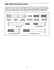
... x 45mm Bolt (76)–-4 M10 x 45mm Screw (75)–-6 M10 x 85mm Screw (74)–-4 5 The number in the hardware kit, check to identify the small parts needed for assembly. If a part is not in parentheses below to see if it has been preassembled. Note: If a part is missing, please call 1-888-533-1333. Extra parts may be included. PART IDENTIFICATION CHART Use the...
... x 45mm Bolt (76)–-4 M10 x 45mm Screw (75)–-6 M10 x 85mm Screw (74)–-4 5 The number in the hardware kit, check to identify the small parts needed for assembly. If a part is not in parentheses below to see if it has been preassembled. Note: If a part is missing, please call 1-888-533-1333. Extra parts may be included. PART IDENTIFICATION CHART Use the...

English Manual
Page 6
...While a second person lifts the rear of the Frame (1), attach the Rear Stabilizer (70) to the Frame 2 with two M10 x 85mm Screws (74). 70 1 74 6 Do not dispose of the packing materials until you nish all parts in a cleared area and remove the packing materials. Go to www... assembly requires the following benefits: •• activates your product manufacturer’'s warranty •• saves you time if you ever need to contact Customer Care •• allows us to notify you of upgrades and offers Note: If you do not use power tools. 1. To avoid damaging parts,...
...While a second person lifts the rear of the Frame (1), attach the Rear Stabilizer (70) to the Frame 2 with two M10 x 85mm Screws (74). 70 1 74 6 Do not dispose of the packing materials until you nish all parts in a cleared area and remove the packing materials. Go to www... assembly requires the following benefits: •• activates your product manufacturer’'s warranty •• saves you time if you ever need to contact Customer Care •• allows us to notify you of upgrades and offers Note: If you do not use power tools. 1. To avoid damaging parts,...
English Manual
Page 9
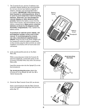
... damaging the console, use only a manufacturer-supplied power adapter. Orient the Rear Console Cover (81) as shown by the diagrams inside the battery compartment on the cover of the power adapter into an outlet installed in accordance with four M4 x 16mm Screws (53). ies together. Make sure to the Sensor Wires (28). 7. To purchase an optional power adapter, call the telephone number on the console; Plug one end of this manual. Untie...
... damaging the console, use only a manufacturer-supplied power adapter. Orient the Rear Console Cover (81) as shown by the diagrams inside the battery compartment on the cover of the power adapter into an outlet installed in accordance with four M4 x 16mm Screws (53). ies together. Make sure to the Sensor Wires (28). 7. To purchase an optional power adapter, call the telephone number on the console; Plug one end of this manual. Untie...
English Manual
Page 10
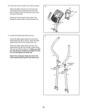
... fully tighten the Bolts yet. Orient the Front Console Cover (32) as shown. Identify the Right Upper Body Arm (9). 11 Orient the Right Upper Body Arm (9) and an Upper Body Leg (6) as shown. 10 Attach the Rear Console Cover (81) around the Upright (2) by pressing the hooks on the Front Console Cover (32). Insert the Right Upper Body Arm into the tabs on the Rear Console Cover into the Upper Body Leg. Attach the Right Upper Body Arm...
... fully tighten the Bolts yet. Orient the Front Console Cover (32) as shown. Identify the Right Upper Body Arm (9). 11 Orient the Right Upper Body Arm (9) and an Upper Body Leg (6) as shown. 10 Attach the Rear Console Cover (81) around the Upright (2) by pressing the hooks on the Front Console Cover (32). Insert the Right Upper Body Arm into the tabs on the Rear Console Cover into the Upper Body Leg. Attach the Right Upper Body Arm...
English Manual
Page 11
... Body Arm (9) with the Bolt Set (31). Attach the right Upper Body Leg (6) to the Right Pedal Arm (49) with an M8 x 20mm Screw (80) and an M8 Washer (33). Slide the Right Upper Body Arm (9) onto the Upright (2). Repeat this step on the other side of the Upright (2). Using a small plastic bag to keep your fingers clean, apply a generous amount of the included 12 grease to a Bolt Set...
... Body Arm (9) with the Bolt Set (31). Attach the right Upper Body Leg (6) to the Right Pedal Arm (49) with an M8 x 20mm Screw (80) and an M8 Washer (33). Slide the Right Upper Body Arm (9) onto the Upright (2). Repeat this step on the other side of the Upright (2). Using a small plastic bag to keep your fingers clean, apply a generous amount of the included 12 grease to a Bolt Set...
English Manual
Page 12
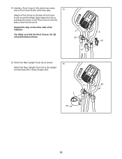
Orient the Rear Upright Cover (3) as shown. 8 19 22 19 15. 14. Tip: Make sure that the Pivot Covers (19, 22) are positioned as shown. 15 Attach the Rear Upright Cover (3) to the Upright (2) with three M4 x 16mm Screws (53). 2 3 53 9 22 53 12 Identify a Pivot Cover A (19), which has hooks, and a Pivot Cover B (22), which has tabs. 14 Attach a Pivot Cover A (19) and a Pivot Cover B (22) around the Right Upper Body Arm (9) by pressing the hooks on the Pivot Cover A onto the tabs on the other side of the elliptical. Repeat this step on the Pivot Cover B.
Orient the Rear Upright Cover (3) as shown. 8 19 22 19 15. 14. Tip: Make sure that the Pivot Covers (19, 22) are positioned as shown. 15 Attach the Rear Upright Cover (3) to the Upright (2) with three M4 x 16mm Screws (53). 2 3 53 9 22 53 12 Identify a Pivot Cover A (19), which has hooks, and a Pivot Cover B (22), which has tabs. 14 Attach a Pivot Cover A (19) and a Pivot Cover B (22) around the Right Upper Body Arm (9) by pressing the hooks on the Pivot Cover A onto the tabs on the other side of the elliptical. Repeat this step on the Pivot Cover B.

English Manual
Page 14
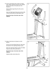
Make sure that all parts of the elliptical. 13 49 78 75 20. Note: Extra parts may be included. To protect the floor or carpet from damage, place a mat under the elliptical. 14 Make sure to use the center hole and the two outer holes to the Right Pedal Arm (49) with three M10 x 45mm Screws (75) and three M10 Split Washers (78). Identify the Right Pedal (13). 19 Attach the Right Pedal (13) to attach the Right Pedal. Repeat this step on the other side of the elliptical are properly tightened. 19.
Make sure that all parts of the elliptical. 13 49 78 75 20. Note: Extra parts may be included. To protect the floor or carpet from damage, place a mat under the elliptical. 14 Make sure to use the center hole and the two outer holes to the Right Pedal Arm (49) with three M10 x 45mm Screws (75) and three M10 Split Washers (78). Identify the Right Pedal (13). 19 Attach the Right Pedal (13) to attach the Right Pedal. Repeat this step on the other side of the elliptical are properly tightened. 19.
English Manual
Page 15
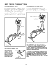
... desired location, and then lower it requires two persons. Then, step off the highest pedal first. Pull on the upright and have a free wheel; Upper Body Arms Handlebars Upright Pedals Place your floor during use, turn the pedal discs in either direction. Note: The pedal discs can turn one of the elliptical, moving it to a complete stop. Note: The elliptical does not have a second person lift the handle on the rear...
... desired location, and then lower it requires two persons. Then, step off the highest pedal first. Pull on the upright and have a free wheel; Upper Body Arms Handlebars Upright Pedals Place your floor during use, turn the pedal discs in either direction. Note: The pedal discs can turn one of the elliptical, moving it to a complete stop. Note: The elliptical does not have a second person lift the handle on the rear...
English Manual
Page 16
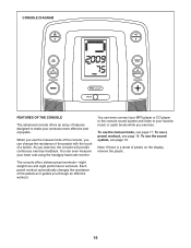
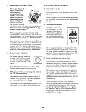
... preset workout automatically changes the resistance of the pedals as it guides you exercise, the console will provide continuous exercise feedback. The console offers sixteen preset workouts—-eight weight loss and eight performance workouts. To use the sound system, see page 19. You can even measure your heart rate using the handgrip heart rate monitor. Note: If there is a sheet of plastic on the display, remove the plastic. To use the manual mode...
... preset workout automatically changes the resistance of the pedals as it guides you exercise, the console will provide continuous exercise feedback. The console offers sixteen preset workouts—-eight weight loss and eight performance workouts. To use the sound system, see page 19. You can even measure your heart rate using the handgrip heart rate monitor. Note: If there is a sheet of plastic on the display, remove the plastic. To use the manual mode...
English Manual
Page 17
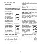
..., distance, speed, and time display modes in the workout. Distance—-This display mode will show a track representing 1/4 mile (400 m). Pulse—-This display mode will show the approximate number of the pedals for the pedals to turn on . Track—-When the manual mode is selected, this display mode will be ready for use the handgrip heart rate monitor (see step 5 on the console. When you use . 2. If you have selected a workout, reselect the manual mode by pressing the Resistance increase and decrease buttons. Workouts button...
..., distance, speed, and time display modes in the workout. Distance—-This display mode will show a track representing 1/4 mile (400 m). Pulse—-This display mode will show the approximate number of the pedals for the pedals to turn on . Track—-When the manual mode is selected, this display mode will be ready for use the handgrip heart rate monitor (see step 5 on the console. When you use . 2. If you have selected a workout, reselect the manual mode by pressing the Resistance increase and decrease buttons. Workouts button...
English Manual
Page 18
... heart rate will appear in the display. In addition, make sure that your hands excessively or to turn off and the display will be reset. Turn on the console. Turn on the fan if desired. Select a preset workout. If the pedals do not move your hands are positioned as described. To measure your pulse is programmed for at least 15 seconds. 1. HOW TO USE A PRESET WORKOUT...
... heart rate will appear in the display. In addition, make sure that your hands excessively or to turn off and the display will be reset. Turn on the console. Turn on the fan if desired. Select a preset workout. If the pedals do not move your hands are positioned as described. To measure your pulse is programmed for at least 15 seconds. 1. HOW TO USE A PRESET WORKOUT...
English Manual
Page 19
... installation. When you are designed to radio communications. See step 7 on page 17. 5. Measure your progress with the display. Next, press the play music or audio books through the console sound system while you exercise, plug your audio cable is fully plugged in. These limits are finished exercising, the console will automatically adjust to which can be determined by pressing the Resistance buttons. This equipment generates, uses, and can manually...
... installation. When you are designed to radio communications. See step 7 on page 17. 5. Measure your progress with the display. Next, press the play music or audio books through the console sound system while you exercise, plug your audio cable is fully plugged in. These limits are finished exercising, the console will automatically adjust to which can be determined by pressing the Resistance buttons. This equipment generates, uses, and can manually...
English Manual
Page 20
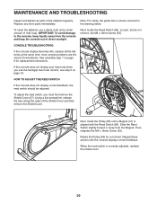
... adjust the reed switch, you use a damp cloth and a small amount of mild soap. Rotate the Pulley (65) for replacement instructions. MAINTENANCE AND TROUBLESHOOTING Inspect and tighten all the batteries at the same time; Note: For clarity, the pedal disc is correctly adjusted, reattach the shield cover. 20 If the console does not display your heart rate when you must first remove the Shield Cover (37). Replace any worn parts immediately. most console problems...
... adjust the reed switch, you use a damp cloth and a small amount of mild soap. Rotate the Pulley (65) for replacement instructions. MAINTENANCE AND TROUBLESHOOTING Inspect and tighten all the batteries at the same time; Note: For clarity, the pedal disc is correctly adjusted, reattach the shield cover. 20 If the console does not display your heart rate when you must first remove the Shield Cover (37). Replace any worn parts immediately. most console problems...
English Manual
Page 21
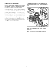
... (see the instructions below). 46 See EXPLODED DRAWING B on page 27. Then, tighten the Drive Belt Adjustment Screw (72) until the Drive Belt (46) is tight, tighten the Pivot Screw (71). Using a flat screwdriver, release the tabs along the sides of Screw you are pedaling, even when the resistance is adjusted to the highest level, the drive belt may need to note which size of the Shield Cover (37), and...
... (see the instructions below). 46 See EXPLODED DRAWING B on page 27. Then, tighten the Drive Belt Adjustment Screw (72) until the Drive Belt (46) is tight, tighten the Pivot Screw (71). Using a flat screwdriver, release the tabs along the sides of Screw you are pedaling, even when the resistance is adjusted to the highest level, the drive belt may need to note which size of the Shield Cover (37), and...
English Manual
Page 22
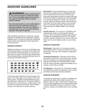
... training zone for a sustained period of your body begin to five workouts each week, with pre-existing health problems. The heart rate monitor is intended only as an exercise aid in determining heart rate trends in your age at a low intensity level for longer than 20 minutes.) Breathe regularly and deeply as a guide to the nearest ten years). The chart below shows recommended heart rates...
... training zone for a sustained period of your body begin to five workouts each week, with pre-existing health problems. The heart rate monitor is intended only as an exercise aid in determining heart rate trends in your age at a low intensity level for longer than 20 minutes.) Breathe regularly and deeply as a guide to the nearest ten years). The chart below shows recommended heart rates...
English Manual
Page 25
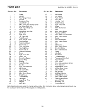
User’'s Manual * –- Qty. Assembly Tool * –- For information about ordering replacement parts, see the back cover of this manual. *These parts are subject to change without notice. PART LIST Model No. 831.23953.3 R1112B Key No. Description 1 1 Frame 2 1 Upright 3 1 Rear Upright Cover 4 1 Console 5 1 Accessory Tray 6 2 Upper Body Leg 7 2 M4 x 12mm Self-tapping Screw 8 1 Left Upper Body Arm 9 1 Right Upper Body Arm 10 2 Foam Grip 11 2 Upper Body Arm Cap 12 1 Left Pedal 13 1 Right Pedal 14 1 Left Pedal Arm 15 2 Pedal Bracket...
User’'s Manual * –- Qty. Assembly Tool * –- For information about ordering replacement parts, see the back cover of this manual. *These parts are subject to change without notice. PART LIST Model No. 831.23953.3 R1112B Key No. Description 1 1 Frame 2 1 Upright 3 1 Rear Upright Cover 4 1 Console 5 1 Accessory Tray 6 2 Upper Body Leg 7 2 M4 x 12mm Self-tapping Screw 8 1 Left Upper Body Arm 9 1 Right Upper Body Arm 10 2 Foam Grip 11 2 Upper Body Arm Cap 12 1 Left Pedal 13 1 Right Pedal 14 1 Left Pedal Arm 15 2 Pedal Bracket...


